ECM JAGUAR X308 1998 2.G Workshop Manual
[x] Cancel search | Manufacturer: JAGUAR, Model Year: 1998, Model line: X308, Model: JAGUAR X308 1998 2.GPages: 2490, PDF Size: 69.81 MB
Page 1311 of 2490

Pinpoint test F: P0715
With EM007 and EM046 disconnected, measure the insulation resistance between EM007/016 and EM007/044 1
Is the resistance > 10 MOHM?
Yes GO to E8
No Inspect harness / connectors EM007 and EM046 for damage,
corrosion, bent / pushed back pins. Repair as necessary and
test the system for normal operation.
E8: END
Perform appropriate service drive cycle and check for the
presence of DTC 1
Has the fault code cleared?
Yes STOP
No Contact Jaguar Service
PINPOINT TEST F : P0715
TEST CONDITIONSDETAILS/RESULTS/ACTIONS
F1: RETRIEVE DTCS
• NOTE: Battery and or ECM disconnection prior to scanning wi ll erase all data, ensure that the correct DTC is present
Page 1316 of 2490

Pinpoint test G: P1722
With EM007 and EM046 disconnected, measure the insulation resistance between EM007/014 and EM007/042 1
Is the resistance > 10 MOHM?
Yes GO to F8
No Inspect harness / connectors EM007 and EM046 for damage,
corrosion, bent / pushed back pins. Repair as necessary and
test the system for normal operation.
F8: END
Perform appropriate service drive cycle and check for the
presence of DTC. 1
Has the fault code cleared?
Yes STOP
No Contact Jaguar Service
PINPOINT TEST G : P1722
TEST CONDITIONSDETAILS/RESULTS/ACTIONS
G1: RETRIEVE DTCS
• NOTE: Battery and or ECM disconnection prior to scanning wi ll erase all data, ensure that the correct DTC is present.
Page 1321 of 2490

Pinpoint test H: P1726
Pinpoint test I: P1730, P1734, P1779
G8: END
Perform appropriate service drive cycle and check for the
presence of DTC. 1
Has the fault code cleared?
Yes STOP
No Contact Jaguar Service
PINPOINT TEST H : P1726
TEST CONDITIONSDETAILS/RESULTS/ACTIONS
H1: RETRIEVE DTCS
• NOTE: Battery and or ECM disconnection prior to scanning wi ll erase all data, ensure that the correct DTC is present.
Connect the scan tool 1
Have the DTC(s) and freeze frame data been recorded?
Yes GO to H2
H2: RENEW TRANSMISSION
Renew the transmission 1
Has the transmission been renewed?
Yes GO to H3
H3: END
Drive the vehicle for a period from cold to include idle, brisk
acceleration and steady state cruising up to and including
normal engine temperature. Check for the presence of DTC 1
Has the fault code cleared?
Yes STOP
No Contact Jaguar Service
PINPOINT TEST I : P1730, P1734, P1779
TEST CONDITIONSDETAILS/RESULTS/ACTIONS
I1: RETRIEVE DTCS
• NOTE: Battery and or ECM disconnection prior to scanning wi ll erase all data, ensure that the correct DTC is present.
Page 1330 of 2490

Pinpoint test J: P1603, P1605, P1608
With EM007 and EM046 disconnected, measure the insulation
resistance between EM007/016 and EM007/044 1
Repeat for EM007/014 and EM007/042 2
Is the resistance > 10 MOHM?
Yes GO to I11
No Inspect harness / connectors EM007 and EM046 for damage,
corrosion, bent / pushed back pins. Repair as necessary and
test the system for normal operation.
I11: END
Perform appropriate service drive cycle and check for the
presence of DTC 1
Has the fault code cleared?
Yes STOP
No Contact Jaguar Service
PINPOINT TEST J : P1603, P1605, P1608
• NOTE: It is important that J3 item 1 is carried out in order that system adaptions take place
TEST CONDITIONSDETAILS/RESULTS/ACTIONS
J1: RETRIEVE DTCS
• NOTE: Following ECM power-down, the DTC will be lost and may only be disp layed when the ignition is energized
Page 1331 of 2490

Pinpoint test K: P1789, P1793
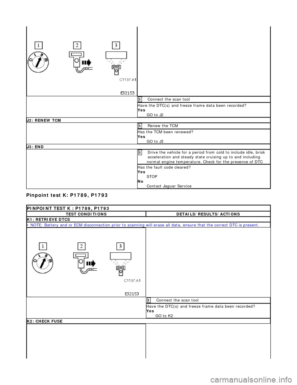
Connect the scan tool 1
Have the DTC(s) and freeze frame data been recorded?
Yes GO to J2
J2: RENEW TCM
Renew the TCM 1
Has the TCM been renewed?
Yes GO to J3
J3: END
Drive the vehicle for a period from cold to include idle, brisk
acceleration and steady state cruising up to and including
normal engine temperature. Check for the presence of DTC 1
Has the fault code cleared?
Yes STOP
No Contact Jaguar Service
PINPOINT TEST K : P1789, P1793
TEST CONDITIONSDETAILS/RESULTS/ACTIONS
K1: RETRIEVE DTCS
• NOTE: Battery and or ECM disconnection prior to scanning wi ll erase all data, ensure that the correct DTC is present.
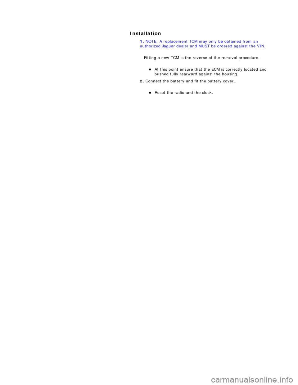
Connect the scan tool 1
Have the DTC(s) and freeze frame data been recorded?
Yes GO to K2
K2: CHECK FUSE
Page 1333 of 2490

Pinpoint test L: P0710
With EM007 and LS008 disconnected, measure the
resistance between EM007/054 and LS008/007 1
Repeat for EM007/055 and LS008/007 2
Is the resistance < 0.5 OHM?
Yes GO to K5
No Inspect harness / connector EM007, LS008, EM051, splice
EMS42 for damage, corrosion, bent / pushed back pins.
Repair as necessary and te st the system for normal
operation.
K5: END
Perform appropriate service drive cycle and check for the
presence of DTC. 1
Has the fault code cleared?
Yes STOP
No Contact Jaguar Service
PINPOINT TEST L : P0710
TEST CONDITIONSDETAILS/RESULTS/ACTIONS
L1: RETRIEVE DTCS
• NOTE: Battery and or ECM disconnection prior to scanning wi ll erase all data, ensure that the correct DTC is present.
Page 1357 of 2490

Automatic Transmission/Transaxle - 4.0L NA V8 - AJ27/3.2L NA V8 - AJ26
- Transmission Control Module (TCM)
In-vehicle Repair
Removal
1. Disconnect battery ground cable.
Remove the battery cover.
2. Remove the trim panel from the engine compartment,
passenger side.
1. Remove the left hand side enclosure panel.
2. If necessary, remove the centre trim panel.
3. Release the fixings and remove the cover from the ECM / TCM
housing.
4. Disconnect the TCM harness multiplug EM007.
5. Lift the TCM from its housing.
Page 1358 of 2490

Installation
1.
NOTE: A replacement TCM may only be obtained from an
authorized Jaguar dealer and MU ST be ordered against the VIN.
Fitting a new TCM is the revers e of the removal procedure.
At this point ensure that the ECM is correctly located and
pushed fully rearward against the housing.
2. Connect the battery and fit the battery cover..
Reset the radio and the clock.
Page 1390 of 2490

Stator, intermediate and output shafts. Three epicyclic geartrains. Six multi-disc clutch/brake packs. Two freewheels (One-way clutches). Hydraulic pump. Parking lock assembly. Electro-hydraulic control unit. Internal harness and 13 pin connector with bayonet lock.
Hydraulic pump
This engine driven pump is located at the front of the transmission casing and provides pressure for the hydraulic
functions.
Supplies fluid under pressure to the torq ue converter, geartrain, electro-hydraulic control unit and the lubrication
circuit.
Draws fluid from the fluid pa n below the transmission casing, through a filter.
Parking lock
This component prevents movement of th e vehicle by engaging a fixed pawl with the parking lock gear located on the
output shaft. The pawl is engaged by movi ng the gear selector lever to the park (P) position.
Electro-hydraulic control unit
This unit, mounted in the transmission lower case, converts signals, mechanical from the J-gate and electrical from the
TCM, into hydraulic functions.
The following components ar e assembled to the unit:
Selector valve. Shift plate. Control valve - modulating pressure. Control valve - shift pressure. Solenoid valve 1 <-> 2 and 4 <-> 5 shift. Solenoid valve 3 <-> 4 shift. Solenoid valve 2 <-> 3 shift. Solenoid valve - converter lock-up. Speed sensors (2). Temperature sensor.
Speed sensors
There are two speed sensors within the transmission assembly which provide input to the TCM. These inputs, when used in
conjunction with CAN data relative to engine speed (from ECM) and road speed (from ABS), are used to electronically
control the transmission.
Temperature sensor
The output from this sensor allows the TCM to compensate for the affect of fluid temperature on shift time and quality
Control Systems
Hydraulic Control
The selector valve is operated directly by the J-gate and directs fluid flow for P R N D.
Of the four solenoid valves, 3 control shifts and 1 controls converter lock-up. One control valve controls modulating pressure
and the other shift pressure.
Regulating valves are used to maintain/control pressure for lu brication, normal operating functions, and the supply to the
control valves and shift valves.
Page 1391 of 2490

In the event of a system fault, the TCM will adopt 'limp home' mode.
Electrical control
Refer to Section 307-01B.
Transmission Control Components
Transmission Control Module (TCM)
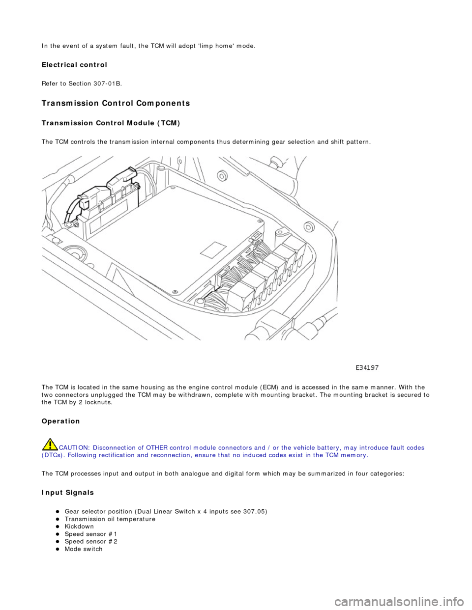
The TCM controls the transmission internal components thus determining gear selection and shift pattern.
The TCM is located in the same housing as the engine control module (ECM) and is accessed in the same manner. With the
two connectors unplugged the TCM may be withdrawn, complete with mounting bracket. The mounting bracket is secured to
the TCM by 2 locknuts.
Operation
CAUTION: Disconnection of OTHER contro l module connectors and / or the vehicle battery, may introduce fault codes
(DTCs). Following rectification and reconnection, ensu re that no induced codes exist in the TCM memory.
The TCM processes input and output in both analogue and di gital form which may be summarized in four categories:
Input Signals
Gear selector position (Dual Linear Switch x 4 inputs see 307.05) Transmission oil temperature Kickdown Speed sensor #1 Speed sensor #2 Mode switch