ECM JAGUAR X308 1998 2.G Workshop Manual
[x] Cancel search | Manufacturer: JAGUAR, Model Year: 1998, Model line: X308, Model: JAGUAR X308 1998 2.GPages: 2490, PDF Size: 69.81 MB
Page 1693 of 2490

Filler Cap and P
ipe
The fuel
filler cap with bayonet-type fixi
ng is located beneath a remote-release sp ring-latched lid on the rear saddle panel
on the left-hand-side of the vehicle.
Fuel Pum
p
The fu
el pump(s) is energized by an ECM co
ntrolled relay. Fuel is drawn by this pu mp and supplied to the fuel injectors via
the fuel line, filter and fuel rails.
Servicing of the fuel pump re quires fuel tank removal.
Ev
aporative Loss Flange Assembly
The evaporative-loss flan
ge asse
mbly is mounted centrally on top of the tank. The flange assembly consists of a removeable
steel cap which mounts the evaporative emissions system vapor outlet valves and, if applicable, a pressure sensor. The
external electrical supply to th e fuel pump(s) is also made via a connector on the flange.
The flange assembly is fixed to the tank by a locking ring which is turned usin g special tool JD-174. A seal is fitted between
the flange assembly and the tank. Three di fferent flange assemblies are applicable according to the evaporative emission
system fitted to the vehicle. The fl ange size and fixing are identical fo r the three systems, as described.
Removal of the evaporative flange assembly is necessary to gain access to th e fuel pump(s) and other internal components.
To remove the evaporative fl ange assembly the fuel tank must first be removed.
The evaporative flange variant assemblies are described, together with service information, in Section 303-13.
Fuel R
eturn
Excess fuel
is directed back to
the fuel tank via a return line.
Fuel Pum
p Relay
The
fuel pump relay,
under control of the ECM, switches power to the fuel pump motor.
I
nertia Fuel Shutoff (IFS) Switch
The IF
S switch is located in the right-hand
side footwell behind the footboard carpet . When activated the switch isolates the
ignition system and fuel pump, releases any locked doors and disables unnecessary electrical systems. The system can be
reset by pressing down the flexible cover on the top of the switch.
• NOTE: The doors will not unlock if the IFS switch is tripped when the ignition switch is in position '0'.
Page 1695 of 2490
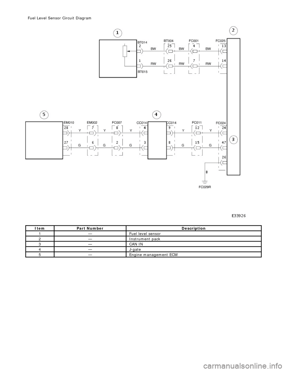
It
em
Par
t Number
De
scription
1—Fue
l level sensor
2—Instrument pack
3—CAN IN
4—J-
gate
5—Engine
management ECM
F
uel Level Sensor Circuit Diagram
Page 1696 of 2490
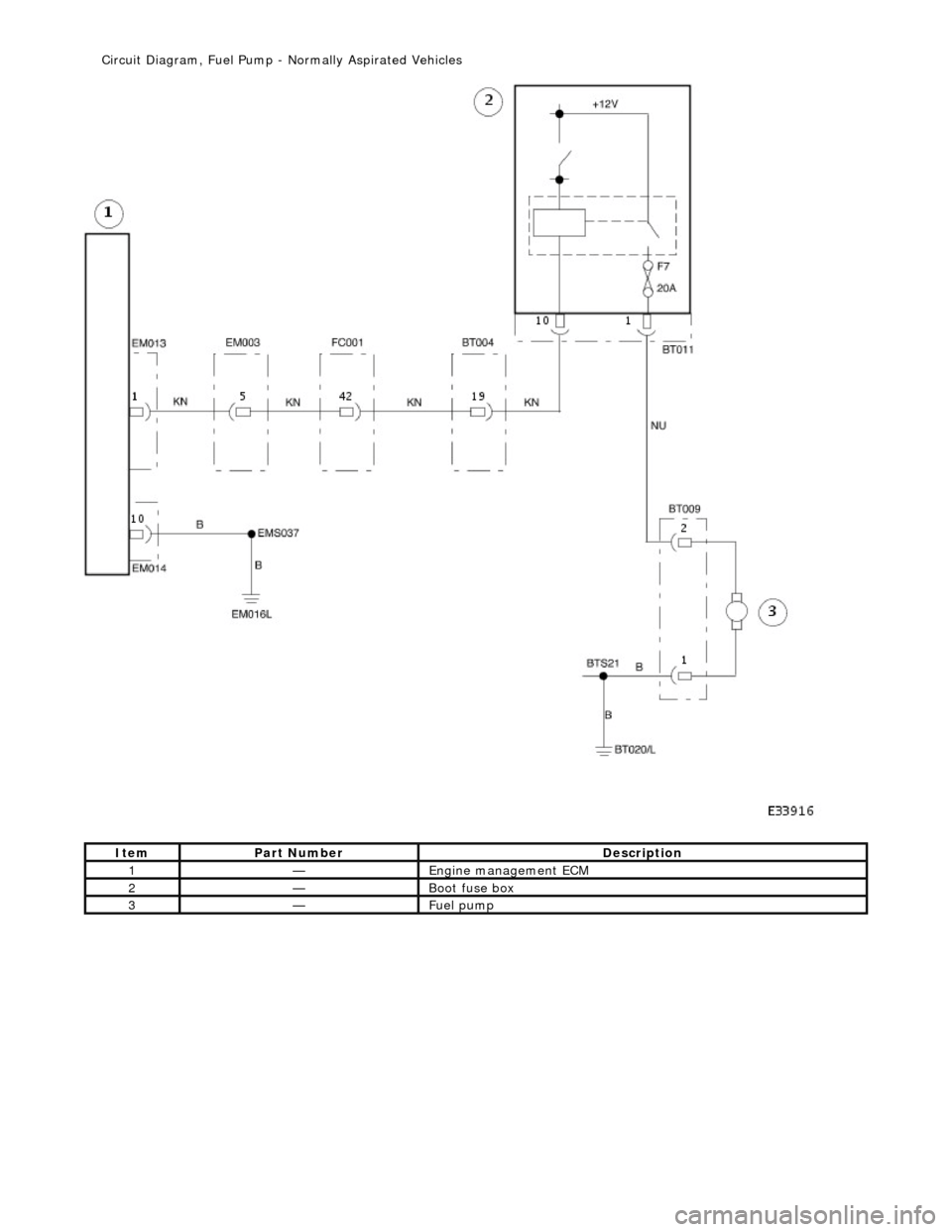
Ite
m
Par
t
Number
De
scr
iption
1—Engine
m
anagement ECM
2—Boot fuse box
3—Fue
l
pump
Ci
rcui
t Diagram, Fuel Pump -
Normally Aspirated Vehicles
Page 1697 of 2490
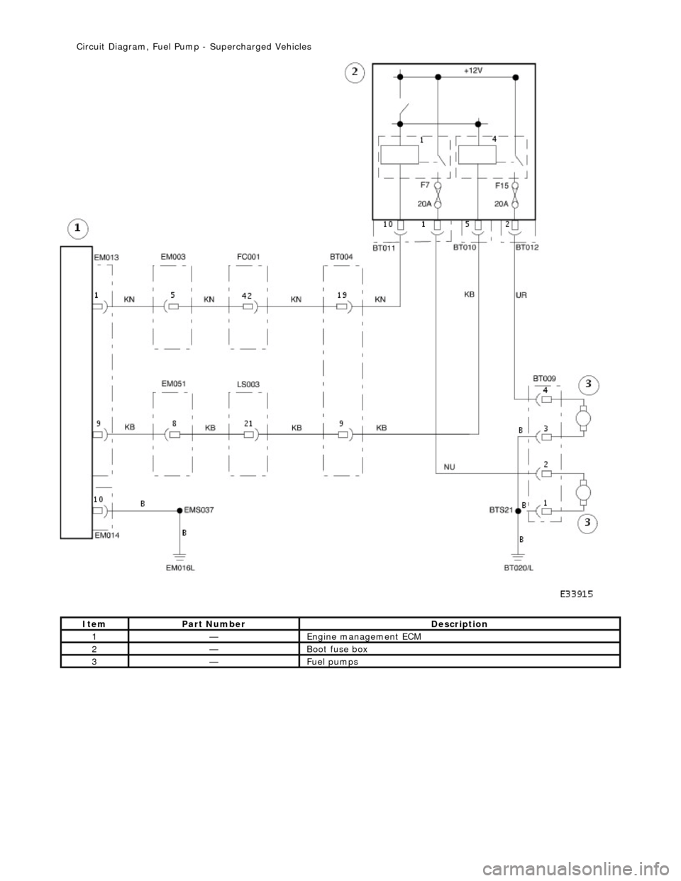
It
em
Par
t Number
De
scription
1—Engine
management ECM
2—Boot fuse box
3—Fue
l pumps
Ci
rcuit Diagram, Fuel Pump
- Supercharged Vehicles
Page 1698 of 2490
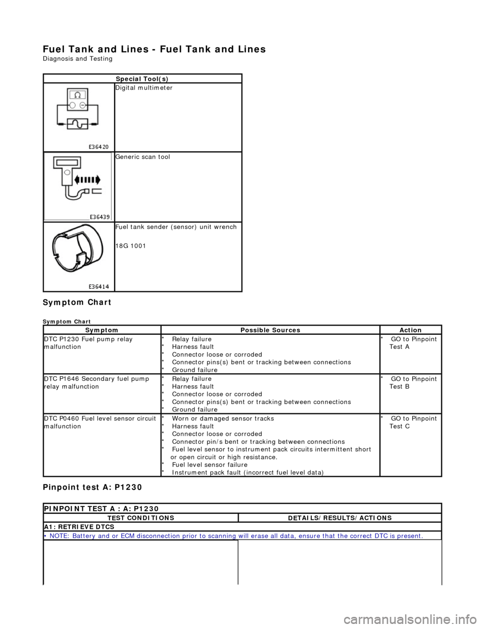
Fuel Tank and Lines - Fuel Tank and Li
nes
D
iagn
osis and Testing
Sym
p
tom Chart
Sy
m
ptom Chart
Pinpoint test A: P1230
S
p
ecial Tool(s)
D
i
gital multimeter
Generi
c scan tool
F
u
el tank sender (sensor) unit wrench
18G 1001
Sy m
ptom
Possib
l
e Sources
Acti
o
n
D
T
C P1230 Fuel pump relay
malfunction
Re lay
failure
Harness fault
Connector loose or corroded
Connector pins(s) bent or tracking between connections
Ground failure
*
*
*
*
*
GO to Pinpoint
Test A
*
D
T
C P1646 Secondary fuel pump
relay malfunction
Re lay
failure
Harness fault
Connector loose or corroded
Connector pins(s) bent or tracking between connections
Ground failure
*
*
*
*
*
GO to Pinpoint
Test B
*
D
T
C P0460 Fuel level sensor circuit
malfunction
Worn
or damaged sensor tracks
Harness fault
Connector loose or corroded
Connector pin/s bent or tracking between connections
Fuel level sensor to instrument pack circui ts intermittent short
or open circuit or high resistance. Fuel level sensor failure
Instrument pack fault (inc orrect fuel level data)
*
*
*
*
*
*
*
GO to Pinpoint
Test C
*
P
INPOINT TES
T A : A: P1230
T
E
ST CONDITIONS
D
E
TAILS/RESULTS/ACTIONS
A1
: RETRIEV
E DTCS
•
NOTE
: Battery and or ECM disconnection prior to scanning wi
ll erase all data, ensure that the correct DTC is present.
Page 1705 of 2490

W
ith EM013 disconnected, measure the resistance
between EM013/001 and relay socket pin 1.
1
I
s the resistance < 0.5 OHM?
Yes GO to A9
No Inspect harness / connec tors EM013, EM003/005,
FC001/42, BT004/019 and BT011/010 for corrosion,
damage, bent or pushed back pins. Repair as required
and test the system for normal operation.
A9: CHECK
ECM GROUND CONTINUITY
Page 1712 of 2490
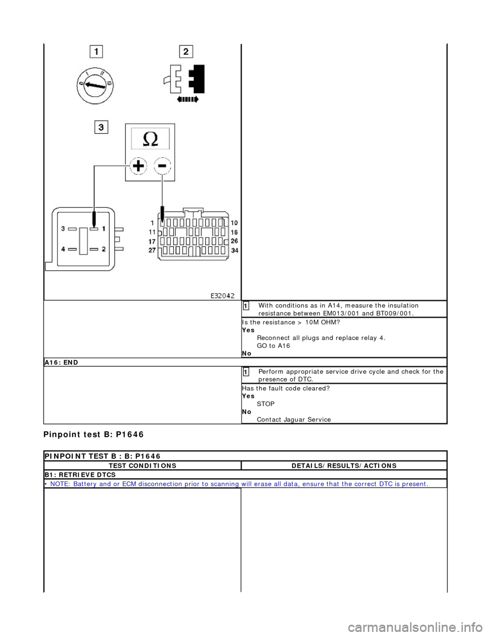
Pinpoint test B:
P1646
W
i
th conditions as in A14, measure the insulation
resistance between EM013/001 and BT009/001.
1
I s
the resistance > 10M OHM?
Yes Reconnect all plugs and replace relay 4.
GO to A16
No
A 16:
END
Perform
a
ppropriate service drive cycle and check for the
presence of DTC.
1
Has th
e fault code cleared?
Yes STOP
No Contact Ja
guar Serv ice
PINPOINT TEST B : B: P1646
TE
ST CONDITIONS
D
E
TAILS/RESULTS/ACTIONS
B1
: RETRI
EVE DTCS
•
NOTE
: Battery and or ECM disconnection prior to scanning wi
ll erase all data, ensure that the correct DTC is present.
Page 1719 of 2490

W
ith EM013 disconnected, measure the resistance
between EM013/009 and relay socket pin 1
1
I
s the resistance < 0.5 OHM?
Yes GO to B9
No Inspect connectors EM013, EM051/008, LS003/21,
BT004/009 and BT010/005 for corrosion, damage, bent or
pushed back pins and repair as required. Test the system
for normal operation
B9: CHECK
ECM GROUND CONTINUITY
Page 1726 of 2490
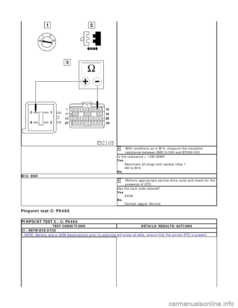
Pinpoint test C: P0460
Wi
th conditions as in B14, measure the insulation
resistance between EM013/009 and BT009/003.
1
I s
the resistance > 10M OHM?
Yes Reconnect all plugs and replace relay 1.
GO to B16
No
B 16:
END
Perform
a
ppropriate service drive cycle and check for the
presence of DTC.
1
Has th
e fault code cleared?
Yes STOP
No Contact Jaguar Service
PI
NPOINT TEST C : C: P0460
T
E
ST CONDITIONS
D
E
TAILS/RESULTS/ACTIONS
C1
: RETRIEVE DTC
S
•
NOTE
: Battery and or ECM disconnection prior to scanning wi
ll erase all data, ensure that the correct DTC is present.
Page 1744 of 2490
Speed Control - Speed
Control
D
iagn
osis and Testing
Pri
n
ciples of operation
The s
p
eed (cruise) control sy
stem is activated by an ON/OFF master switch in the J-gate surround, which has an integral
LED to indicate status.
The steering wheel switches allow the driver to set the speed, increase or decrease the selected speed, cancel and resume
the facility without his/her hand ever leaving the steering wheel
The vehicle speed can be increased an d decreased in increments of 2 kmh (1 mph) by briefly pressing the + or - buttons up
to a maximum of five times.
Alternatively, the + or - button can be held until th e desired speed is reached.
The selected speed (by whichever method) w ill be displayed in the message center.
The system will not function at speeds below 26 kmh (16 mph), and can be cancelled from the master switch, the steering
wheel switches, and by depressing th e brake pedal. The system can be overridden by accelerating as normal.
In
spection and Verification
1.
1. Veri fy the customer concern.
2. 2. Vis
ually inspect for obvious signs of mechanical or electrical damage.
3. 3. If an obvious cause for an observed or reported concern is found, correct the cause (if possible) before proceeding
to the next step.
4. 4. If the cause is not visually evident, verify the symptom, check for DTCs and follow the routines in this section.
Vi
sual Inspection Chart
Diagnostic Trouble Code (D
TC) index
MechanicalElectrical
Throttle body mechan
ism
Throttle body actuator
Module Switch(es) Instrument cluster
DTC
De
scr
iption
Possib
l
e Source
Acti
o
n
P0566Speed
c
ontrol
CANCEL
switch ON fault
Speed
control switches internal steering wheel
short circuit to ground
St
eering wheel cassette reel short circuit to
ground
Cassette reel to ECM circ
uit short circuit to
ground
CANCEL
switch failure (stuck ON)
Fo
r
CANCEL switch circuit
tests,GO to Pinpoint Test A.
P0567Speed c
ontrol
RESUME
switch ON fault
Speed
control switches internal steering wheel
short circuit to ground
St
eering wheel cassette reel short circuit to
ground
Cassette reel to ECM circ
uit short circuit to
ground
RESUME swit
ch failure (stuck ON)
For
RESUME switch circuit
tests,GO to Pinpoint Test B.
P0568Spee
d control switch
ground malfunction
Speed
control switches internal steering wheel
open circuit
St
eering wheel cassette reel open circuit or
high resistance
Cassette reel to ECM ci
rcuit open circuit or high
For
ACCEL/DECEL switch circuit
tests,GO to Pinpoint Test C.