light JAGUAR X308 1998 2.G Workshop Manual
[x] Cancel search | Manufacturer: JAGUAR, Model Year: 1998, Model line: X308, Model: JAGUAR X308 1998 2.GPages: 2490, PDF Size: 69.81 MB
Page 2054 of 2490
Interior Trim and Ornamentation - Interior Trim
Description and Operation
Carpets
The passenger compartment carpet is a one piece moulded constr uction with integral sound deadening material, heel mats
and driver's footrest. The carpet is attach ed to the vehicle floor by plastic clips fitted below the door treadplates. Removal of the carpet necessitates re moval of the front seats, lifting of the centre console rear extens ion and removal of the heelboard
carpet.
Fascia
The full width, slush moulded, soft feel PVC fascia is mounted on an injection moulded armature and is faced with wood
veneer. In addition to the air conditioning and central, outer and demisting vents, it accepts instrument packs dedicated to
market requirements and a centrally mounted analogue clock.
Doors
The one-piece door casings are trimmed in UEV to match the seating, with wood veneer at the waistline and a carpet insert
at the front lower corner. Each casing is secured to the door inner panel by fir tree press fast eners along the lower section,
two armrest fixings at the centre and vene er panel dowels and fixings at the top. The armrests which are common to front
and rear doors, are trimmed in matching leather or UEV according to specification. The door switchpacks, dedicated to
driver and front or rear passenger, are in corporated in the armrests. A speaker is in stalled in the lower section of each door
and a tweeter is incorporated behind each interior door handle escutcheon. Where premium ICE is fitted, the front tweeters
are installed in the upper A posts.
A, B, C and D Posts
On each side,a grained UEV finisher trimmed to match the headlining is secured to the 'A' post and cantrail by fir tree
fasteners locating in BIW apertures. The upper 'D' post finisher is trimmed and secured in the same manner. The single
piece'B/C' post finishers, also finished in grained matching UEV, each have a front se at belt exit aperture and are secured to
the BIW by four spring clips and two fir tree fasteners.
Headlining
The one-piece headlining consists of a 6mm thick polyurethane foam membrane covered with suede effect knitted polyester. The headlining is secured to the BIW roof by body tangs, the roof console, sun visors, combined grab handles and coat
hooks, the cantrail finishers and where fitt ed, the sliding roof finisher and clips.
Trunk
Carpet covered trims line the trunk and are secured by fir tr ee fasteners to the sides and front inner panel. The carpet
covered, two-section, removable trunk fl oor provides access to the spare wheel and wheel changing equipment, the battery
and electrical carrier. The floor board rests on the spare wheel, with the front and rear edges locating in blocks on the fuel
tank backboard and the rear of the body. The support blocks provide for two floor he ight settings to accommodate either a
space saver or full size spare wheel.A moulded finisher covering the rear of the trunk below the sill is secured to the rear
panel by tabs and fir tree fasteners. Finish er panels fitted to the rear lamp units provide trunk interior access to the lamps.
The trunk lid underside is fitted with a removabl e moulded liner and two trunk illumination lights.
Page 2059 of 2490

Interior Trim and Ornamentation - C-Pillar Trim Panel
Removal and Installation
Removal
1. Remove the passenger assist handle.
For additional information, refer to: Passenger Assist Handle
(501-05 Interior Trim and Ornamentation, Removal and
Installation).
2. Detach the rear courtesy/reading light.
3. Remove the rear courtesy/reading light.
Disconnect the electrical connector.
4. Detach the door aperture weatherstrip.
5. Detach the C-pillar trim panel fi r tree fasteners from the BIW.
6. Remove the C-pillar trim pa nel and discard the fir tree
fasteners.
Page 2086 of 2490
Interior Trim and Ornamentation - Parcel Shelf
Removal and Installation
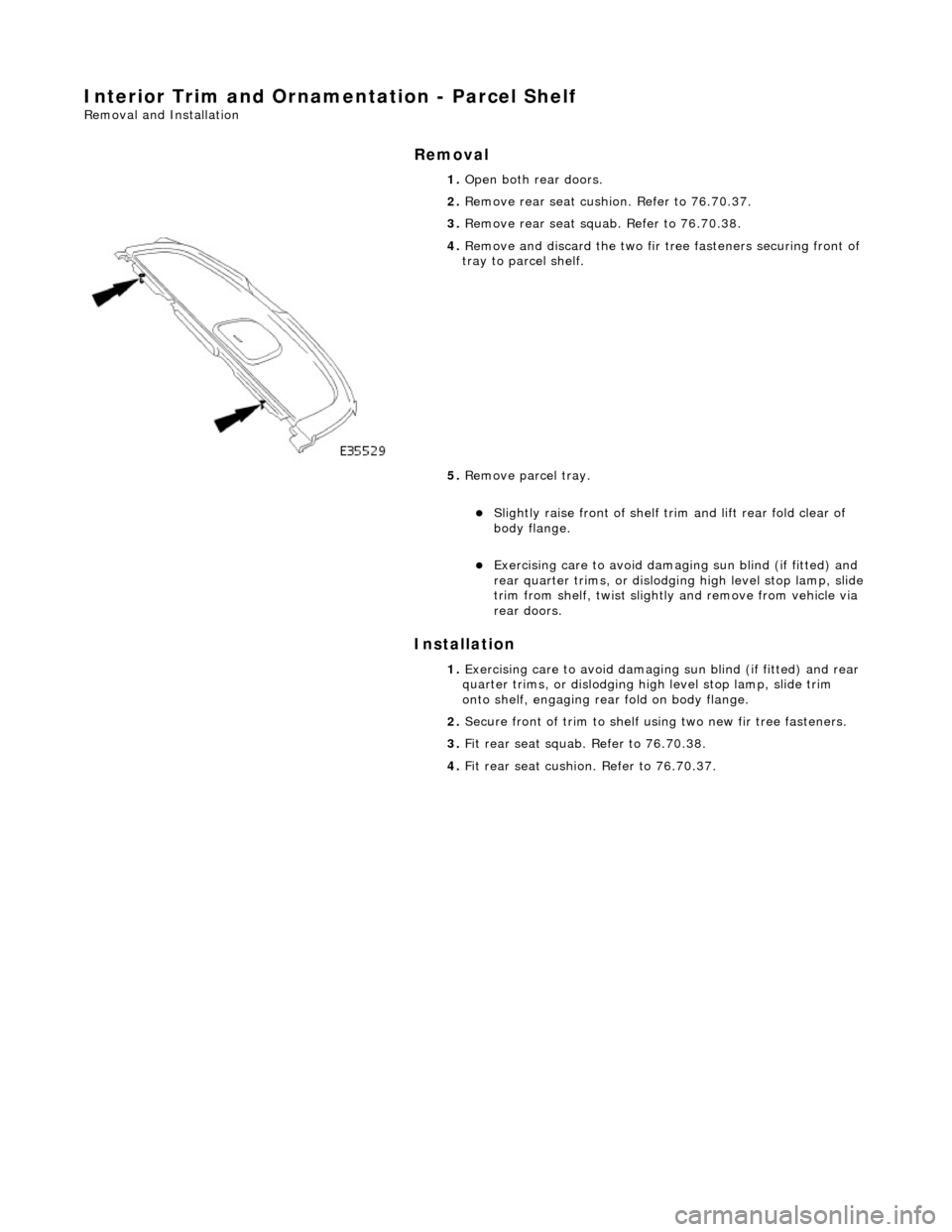
Removal
Installation
1.
Open both rear doors.
2. Remove rear seat cushion. Refer to 76.70.37.
3. Remove rear seat squa b. Refer to 76.70.38.
4. Remove and discard the two fir tr ee fasteners securing front of
tray to parcel shelf.
5. Remove parcel tray.
Slightly raise front of shelf trim and lift rear fold clear of
body flange.
Exercising care to avoid dama ging sun blind (if fitted) and
rear quarter trims, or dislodging high level stop lamp, slide trim from shelf, twist slightly and remove from vehicle via
rear doors.
1. Exercising care to avoid damaging sun blind (if fitted) and rear
quarter trims, or dislodging hi gh level stop lamp, slide trim
onto shelf, engaging rear fold on body flange.
2. Secure front of trim to shelf using two new fir tr ee fasteners.
3. Fit rear seat squab. Refer to 76.70.38.
4. Fit rear seat cushion. Refer to 76.70.37.
Page 2111 of 2490

Rear View Mirrors - Rear View Mirrors
Description and Operation
Interior Rear View Mirror
The interior rear view mirror is an elec trochromic unit that automatically darken s to prevent glare from following vehicle
lights. This automatic function is selected by pressing the switch at the bottom of the mirror. Pressing the switch again
cancels this function. An LE D then illuminates when automatic dipping is operative.
A Night Sentinel light sensing unit also incorporated in the mi rror casing, provides for automatic control of the vehicle lights.
Door Rear View Mirrors
The door mirrors are cheater mounted, colo r-keyed units, remote electrically adjustable and heated. Adjustment of both
mirrors is carried out from the driver's door switchpack. A slider switch selects the mirror to be adjusted, and a disc switch
adjusts the selected mirror to the required position.
Page 2112 of 2490

Mirror adjustment can only be made when the ignition switch is in position I or II or the driver's door is open, and the
selector switch is moved from the central position.
When fitted, electrochromic door mirrors au tomatically darken under control of the interior rear view mirror. Mirror heating
elements operate on selection of backlight heating.
Automatic dipping of passenger door mirror for kerb view when reversing, is fitted as part of the memory pack. With the
ignition switch in position II, the mirror selector switch in the left or right position and reverse gear selected, automatic
dipping is initiated by moving the mirro r toggle switch rearwards and releasing.
On receipt of the dip signal, th e passenger door mirror is driven downwards eith er 7 degrees, bottom of travel, or 4,5 to 5,5
seconds, whichever occurs first. Subsequent rear ward movement of the toggle switch achieves further dipping of the mirror
in the same increments and sequence.
The mirror can be manually returned to the normal memorised position by moving the toggle switch forward with reverse
gear selected. The mirror will automatically return to memorised position on deselection of reverse gear, or moving ignition
switch from position II.
Door mirror fold-back where fitted, to facilitate parking in conf ined spaces, can be initiated when the ignition switch is in
position I or II, the mirror selector switch is in the centra l position and vehicle speed is below 19 km/h (12 mph). Mirror
fold-back is then initiated by moving the toggle switch rear wards and releasing it. The door mirrors are returned to the
normal driving position by ag ain moving toggle switch rearwards. There is no speed constraint on this operation.
In the event of a fold-back mirror becoming 'out of position' du e to accidental impact, it must only be re-positioned by
initiating the fold-back sequence.
Loss of power supplies will result in loss of mirror fold-back memory. In the event of such a memory loss with mirrors in the
normal position, fold-back will operate on second movement of the toggle swit ch. On loss of memory with mirrors in the
fold-back position, they will return to the no rmal position on next fold-back operation.
Page 2179 of 2490
Glass, Frames and Mechanisms - Glass, Frames and Mechanisms
Description and Operation
Fixed Glass
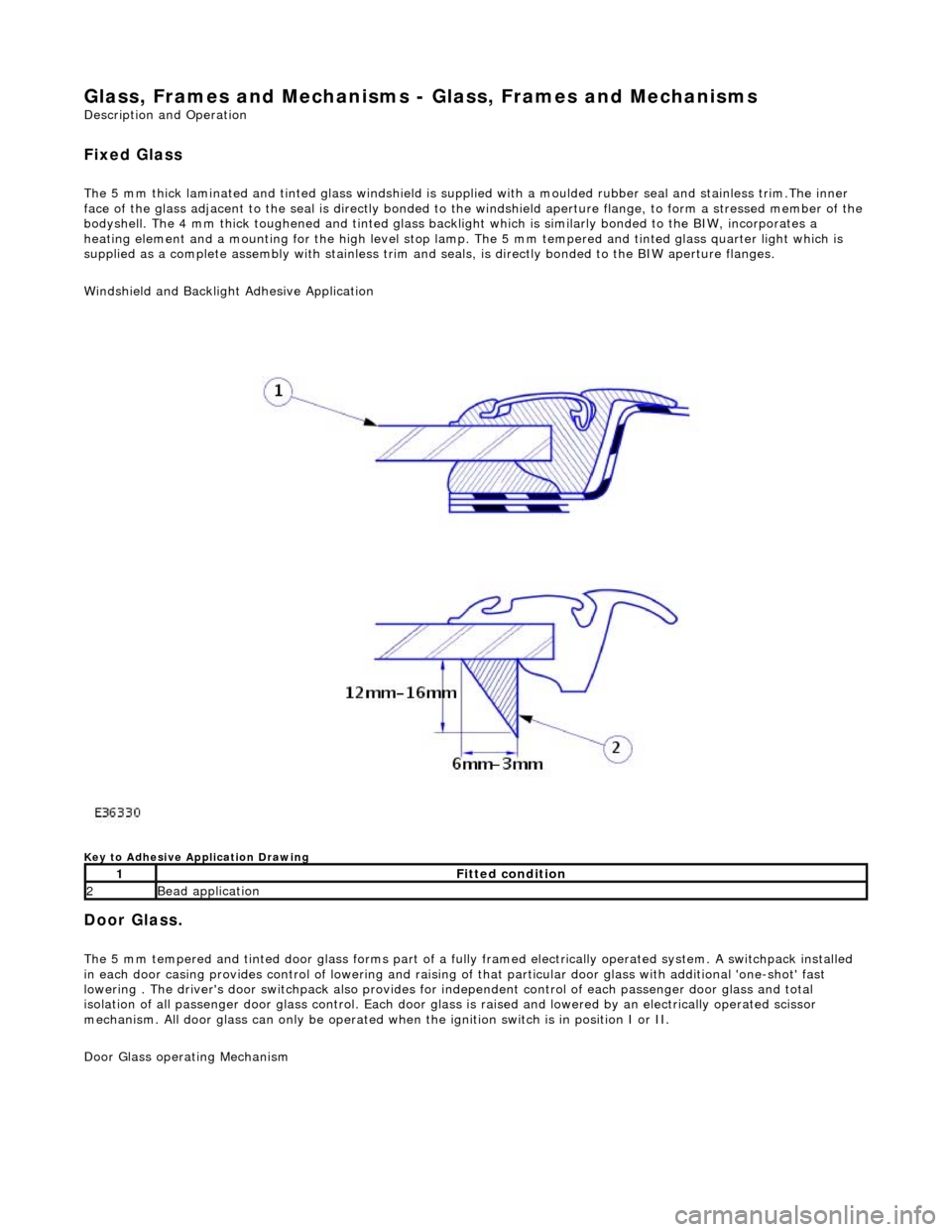
The 5 mm thick laminated and tinted glas s windshield is supplied with a moulded rubber seal and stainless trim.The inner
face of the glass adjacent to the seal is directly bonded to the windshield aperture flange, to form a stressed member of the
bodyshell. The 4 mm thick toughened and tinted glass backlight which is similarly bonded to the BIW, incorporates a
heating element and a mounting for the high level stop lamp. The 5 mm tempered and tinted glass quarter light which is
supplied as a complete assembly with stainless trim and seals, is directly bonded to the BIW aperture flanges.
Windshield and Backlight Adhesive Application
Key to Adhesive Application Drawing
Door Glass.
The 5 mm tempered and tinted door glass forms part of a fully framed electrically operated system. A switchpack installed
in each door casing provides control of lowering and raising of that particular d oor glass with additional 'one-shot' fast
lowering . The driver's door switchpack also provides for independent control of each passenger door glass and total
isolation of all passenger door glass control. Each door glas s is raised and lowered by an electrically operated scissor
mechanism. All door glass can only be operated wh en the ignition switch is in position I or II.
Door Glass operating Mechanism
1Fitted condition
2Bead application
Page 2205 of 2490
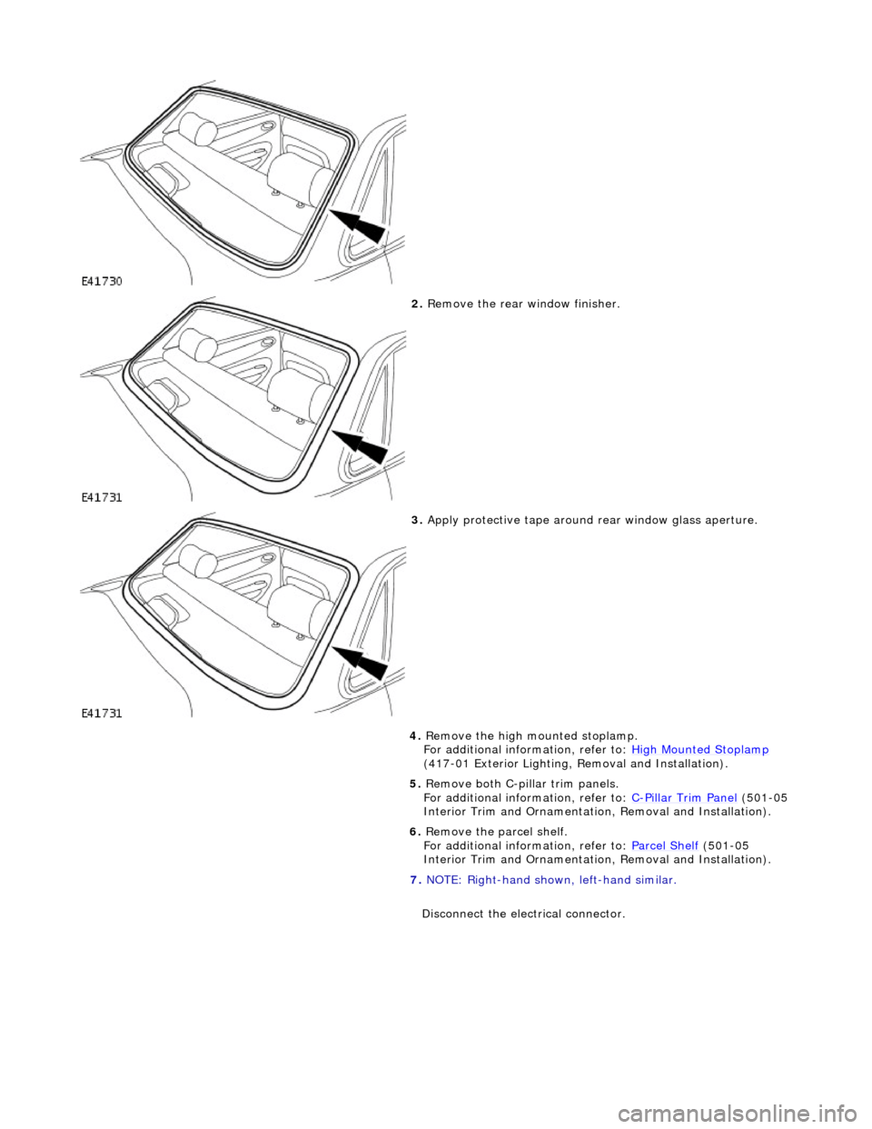
2. Remove the rear window finisher.
3. Apply protective tape around rear window glass aperture.
4. Remove the high mounted stoplamp.
For additional information, refer to: High Mounted Stoplamp
(417-01 Exterior Lighting, Removal and Installation).
5. Remove both C-pill ar trim panels.
For additional information, refer to: C
-Pillar Trim Panel (501-05
Interior Trim and Ornamentatio n, Removal and Installation).
6. Remove the parcel shelf.
For additional information, refer to: Parcel Shelf
(501-05
Interior Trim and Ornamentatio n, Removal and Installation).
7. NOTE: Right-hand shown, left-hand similar.
Disconnect the electrical connector.
Page 2211 of 2490

For additional information, refer to: C
-Pillar Trim Panel (501-05
Interior Trim and Ornamentatio n, Removal and Installation).
15. Install the high mounted stoplamp.
For additional information, refer to: High Mounted Stoplamp
(417-01 Exterior Lighting, Removal and Installation).
Page 2224 of 2490

Instrument Panel and Console - Floor Console
Removal and Installation
Removal
1. Turn ignition switch to posi tion II and apply footbrake.
2. Move gear selector to the the 'D' position. and release
footbrake.
3. Turn ignition switch to position'O'
4. Remove battery cover and disc onnect ground cable from
battery terminal. Refer to 86.15.19.
5. Where fitted, remove centre cons ole rear extension. Refer to
76.25.05.
6. Remove fascia centre veneer panel. Refer to 76.47.06.
7. Using a thin plastic lever, ca refully release the rear air
distribution control grill tang s at top and sides and remove
grill complete with veneer panel and control.
8. Disconnect cigar lighter and ashtray illumination harness
(white) multiplug at RH rear. of console.
9. Slacken and remove the two co nsole rear securing screws.
10. Remove 'J' gate finisher and veneer panel. Refer to 76.25.24
and 76.25.26.
11. Remove fascia centre veneer panel. Refer to 76.47.06.
Page 2225 of 2490
Installation
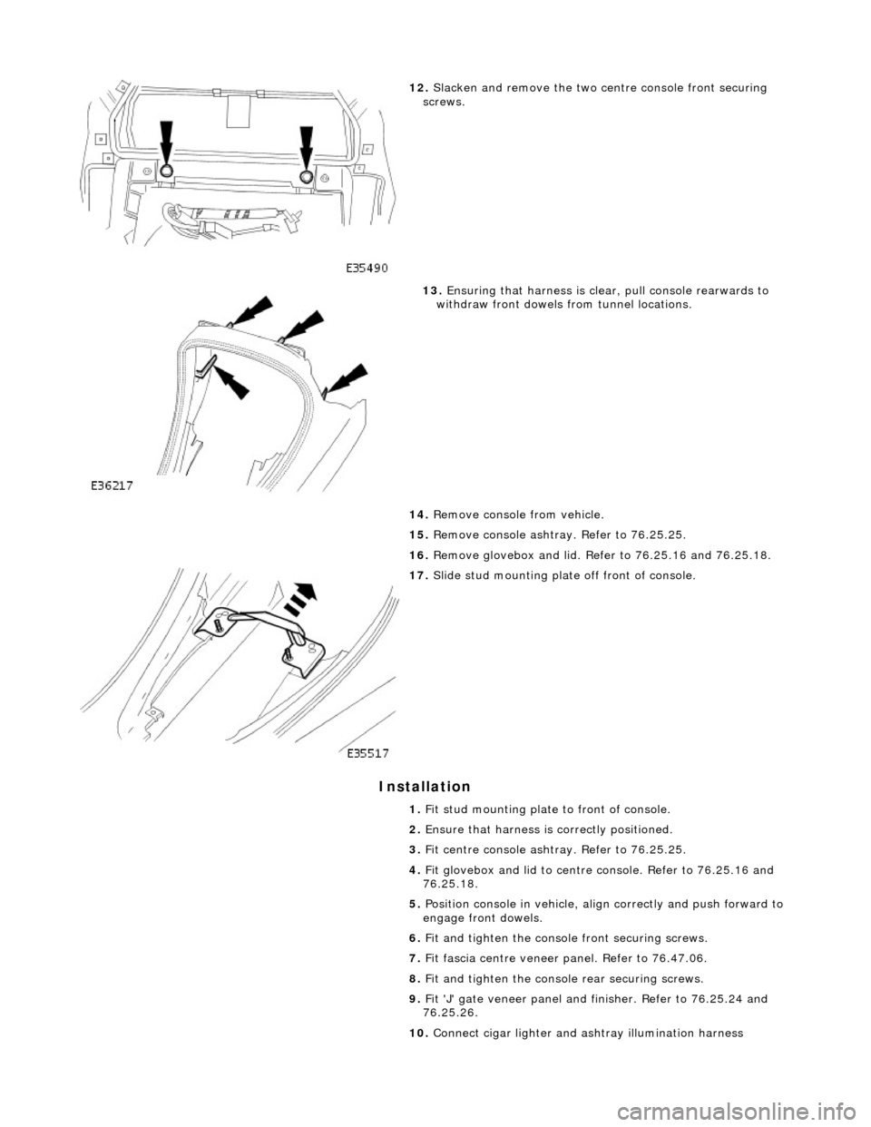
12. Slacken and remove the two ce ntre console front securing
screws.
13. Ensuring that harness is clea r, pull console rearwards to
withdraw front dowels from tunnel locations.
14. Remove console from vehicle.
15. Remove console ashtray. Refer to 76.25.25.
16. Remove glovebox and lid. Refer to 76.25.16 and 76.25.18.
17. Slide stud mounting plate off front of console.
1. Fit stud mounting plate to front of console.
2. Ensure that harness is correctly positioned.
3. Fit centre console ashtray. Refer to 76.25.25.
4. Fit glovebox and lid to centre console. Refer to 76.25.16 and
76.25.18.
5. Position console in vehicle, align correctly and push forward to
engage front dowels.
6. Fit and tighten the consol e front securing screws.
7. Fit fascia centre veneer panel. Refer to 76.47.06.
8. Fit and tighten the console rear securing screws.
9. Fit 'J' gate veneer panel and finisher. Refer to 76.25.24 and
76.25.26.
10. Connect cigar lighter and as htray illumination harness