light JAGUAR X308 1998 2.G Workshop Manual
[x] Cancel search | Manufacturer: JAGUAR, Model Year: 1998, Model line: X308, Model: JAGUAR X308 1998 2.GPages: 2490, PDF Size: 69.81 MB
Page 2391 of 2490

ZINC COATED PANELS
Description
Approximately 70% of the 'body in white' (BIW) mass is made up of zinc coated panels.
• NOTE: To maintain the protective qualities of the zinc trea tment, repairs to any damaged coated area must be made as
soon as possible after the damage has occurred.
All exterior skin panels, with the exceptio n of the roof, are double side zinc plated and this coating (nominally 7,5 microns)
provides two way corrosion protection. Should the outer layer of paint become chipped with the zinc coating remain intact,
the zinc will oxidize on contact with air and being impermeable, this coat of oxidation will prevent corrosion damage of the
base metal. If the outer layer of paint and the zinc coating become damaged, the zinc rather than the base metal will react
with the air and 'sacrifice' itself to corrosion as a 'sacrificial anode'.
Welding Preparation
Contamination of the weld with resultant reduction in joint st rength increase and increased electrode tip dressing frequency
will occur zinc coating is not removed. In exceptional cases where the zinc coating must remain intact, the tip pressure and
welding current should be increased by 10 to 20%.
Where 'resistance spot welding' is employed, the zinc coatin g should be lightly abraded away on the mating surfaces and
those in contact with the electrode tips. Do not remove more zinc coating than is absolutely necessary.
Before welding, a weld-through primer or inter-weld sealer should be applied, as detailed in the Body Sealing and
Preservation manual.
Where MIG welding is used as an alternativ e to resistance spot welding for plug and butt welds or due to limited access, the
problems caused by the presence of zinc coating are much the same, with the added complication of increased weld spatter
and nozzle contamination.
Body Fillers
Conventional polyester fillers do not adhere satisfactorily to zinc plated panels, it is ther efore important that only those
products specifically designed for this application are used and the manufacturer's recommendations are followed.
Refinishing
Use only those products approved by Jaguar Cars Ltd and exercise special care on zinc coated panels.
As replacement panels ar e supplied ready primed, the only bare metal that needs to be exposed are those areas prepared
for welding etc, as decribed in 'Welding Preparation. Where any part of a panel is dressed back to the bare surface, it should
be treated with a zinc rich primer compatible with the paint application system.
GENERAL PREPARATION OF PANELS
Removal of Panels and Welds
• NOTE: Where other components must be removed for access, refer to the relevant manual section for guidance. This is
particularly important where steerin g, braking, suspension, electrical and safety systems are affected.
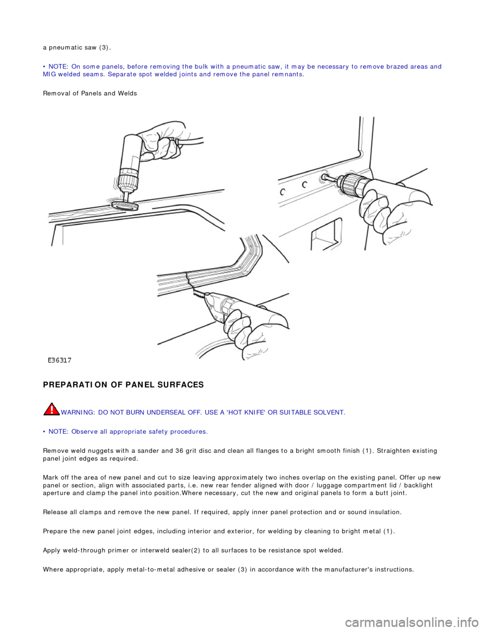
Expose all resistance spot welds, using a ro tary wire brush fitted to an air drill or a hand held wire brush on those that are
not clearly visible (1).
WARNING: DO NOT BURN UNDERSEAL OFF. USE A 'HOT KNIFE' OR SUITABLE SOLVENT.
Cut out spot welds using a Zipcutter or Roto-Bor (2). At this point it may be necessary to cut out the bulk of the panel using
Page 2392 of 2490

a pneumatic saw (3).
• NOTE: On some panels, before removing the bulk with a pneumatic saw, it may be necessary to remove brazed areas and
MIG welded seams. Separate spot welded joints and remove the panel remnants.
Removal of Panels and Welds
PREPARATION OF PANEL SURFACES
WARNING: DO NOT BURN UNDERSEAL OFF. USE A 'HOT KNIFE' OR SUITABLE SOLVENT.
• NOTE: Observe all appropriate safety procedures.
Remove weld nuggets with a sander and 36 gr it disc and clean all flanges to a bright smooth finish (1). Straighten existing
panel joint edges as required.
Mark off the area of new panel and cut to size leaving approxim ately two inches overlap on the existing panel. Offer up new
panel or section, align with associated pa rts, i.e. new rear fender aligned with door / luggage compartment lid / backlight
aperture and clamp the panel into positi on.Where necessary, cut the new and orig inal panels to form a butt joint.
Release all clamps and remove the new panel. If required, apply inner panel protection and or sound insulation.
Prepare the new panel joint edges, including interior and exterior, for welding by cleaning to bright metal (1).
Apply weld-through primer or in terweld sealer(2) to all surfaces to be resistance spot welded.
Where appropriate, apply metal- to-metal adhesive or sealer (3) in accordance with the manufacturer's instructions.
Page 2407 of 2490

For coachline specifications, see page? .
Tape Application
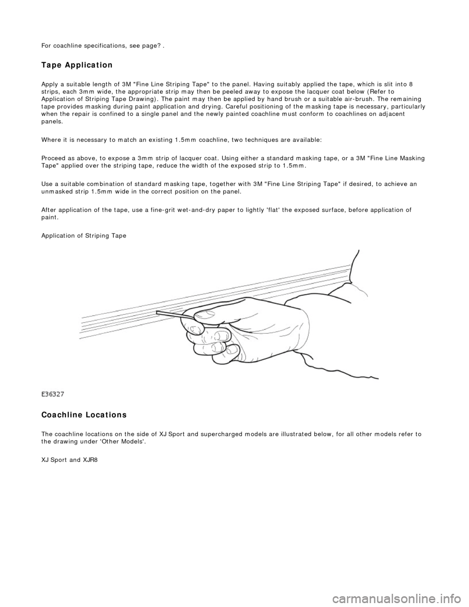
Apply a suitable length of 3M "Fine Line Striping Tape" to the panel. Having suitably applied the tape, which is slit into 8
strips, each 3mm wide, the appr opriate strip may then be peeled away to expose the lacquer coat below (Refer to
Application of Striping Tape Drawing). The paint may then be applied by hand brush or a suitable air-brush. The remaining
tape provides masking during paint applicat ion and drying. Careful positioning of the masking tape is necessary, particularly
when the repair is confined to a single panel and the newly painted coachline mu st conform to coachlines on adjacent
panels.
Where it is necessary to match an existing 1.5mm coachline, two tec hniques are available:
Proceed as above, to expose a 3mm strip of lacquer coat. Using either a standard masking tape, or a 3M "Fine Line Masking
Tape" applied over the striping tape, reduce the width of the exposed strip to 1.5mm.
Use a suitable combination of standard mask ing tape, together with 3M "Fine Line Striping Tape" if desired, to achieve an
unmasked strip 1.5mm wide in the correct position on the panel.
After application of the tape, use a fine-g rit wet-and-dry paper to lightly 'flat' the exposed surface, before application of
paint.
Application of Striping Tape
Coachline Locations
The coachline locations on the side of XJ Sport and supercharged models are illustrated below, for all other models refer to
the drawing under 'Other Models'.
XJ Sport and XJR8
Page 2410 of 2490

GLAZING
In order that the design condition of the vehicle is preserved when direct glazing repairs are carried out, it is essential that
only approved materials an d processes are employed.
Glass and Body Preparation
Betaseal HV3 System methods an d materials, are used on all Jaguar vehicles . Ease of working and extended process time
can however be gained by ensuring that the vehicle body and replacement glass are at a minimum room temperature of 20°
C prior to adhesive a pplication and fitting.
In the event of damage to the body flange finish, rectify as appropriate with the full paint refinishing process as described in
the Paint Refinishing Manual.
Adhesive Application Temperature
The specified adhesive has a high viscosity and is not easily applied at 'room te mperature' using conventional methods.
When the adhesive is applied it chills ra pidly on contact with the body and reverts to the hard condition, providing retention
strength with in minutes.
Raising the temperature of the adhesive will reduce viscosity an d speed up the flow. It is recommended that the adhesive is
pre-warmed in a heated cabinet for a mini mum of twenty minutes and applied with an extrusion gun incorporating integral
heating elements.
Adhesive Application
CAUTION: The glass will not bond to the body if the time taken to apply the adhesive and position the glass, exceeds
the stated limit.
It is recommended that the be ad of adhesive conforms to the shape and dimensions shown in the Adhesive Application
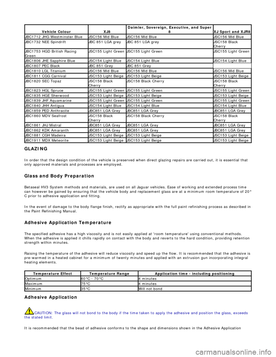
Vehicle ColourXJ8Daimler, Sovereign, Executive, and Super
8XJ Sport and XJR8
JBC1712 JHG Westminster BlueJSC156 Mid BlueJSC156 Mid BlueJSC156 Mid Blue
JBC1732 NEE SpindriftJBC 851 LGA greyJBC 851 LGA greyJSC158 Black
Cherry
JBC1753 HGD British Racing
GreenJSC155 Light GreenJSC155 Light GreenJSC155 Light Green
JBC1806 JHE Sapphire BlueJSC154 Light BlueJSC154 Light BlueJSC154 Light Blue
JBC1807 PEC BlackJBC 851 GreyJBC 851 Grey
JBC1810 LGL TitaniumJSC156 Mid BlueJSC156 Mid BlueJSC156 Mid Blue
JBC1811 CGG CarnivalJSC153 Light BeigeJSC153 Light BeigeJSC153 Light Beige
JBC1820 SEC TopazJSC158 Black
CherryJSC158 Black CherryJSC158 Black
Cherry
JBC1823 HGL SpruceJSC155 Light GreenJSC155 Light GreenJSC155 Light Green
JBC1835 HGE SherwoodJSC153 Light BeigeJSC153 Light BeigeJSC153 Light Beige
JBC1839 JHF AquamarineJSC155 Light GreenJSC155 Light GreenJSC155 Light Green
JBC1840 JHH AntiguaJSC154 Light BlueJSC154 Light BlueJSC154 Light Blue
JBC1859 PED AnthraciteJBC851 LGA GreyJBC851 LGA GreyJBC851 LGA Grey
JBC1860 MDV SeafrostJSC158 Black
CherryJSC158 Black CherryJSC158 Black
Cherry
JBC1861 JHJ MistralJBC851 LGA GreyJBC851 LGA GreyJBC851 LGA Grey
JBC1862 KDK AmaranthJBC851 LGA GreyJBC851 LGA GreyJBC851 LGA Grey
JBC1881 CGH MadeiraJSC153 Light BeigeJSC153 Light BeigeJSC153 Light Beige
JBC1911 MDX MeteoriteJSC153 Light BeigeJSC153 Light BeigeJSC153 Light Beige
Temperature EffectTemperature RangeApplication time - including positioning
Optimum60°C - 70°C4 minutes
Maximum75°C4 minutes
Minimum35°CWill not bond