speed JAGUAR X308 1998 2.G Workshop Manual
[x] Cancel search | Manufacturer: JAGUAR, Model Year: 1998, Model line: X308, Model: JAGUAR X308 1998 2.GPages: 2490, PDF Size: 69.81 MB
Page 1365 of 2490
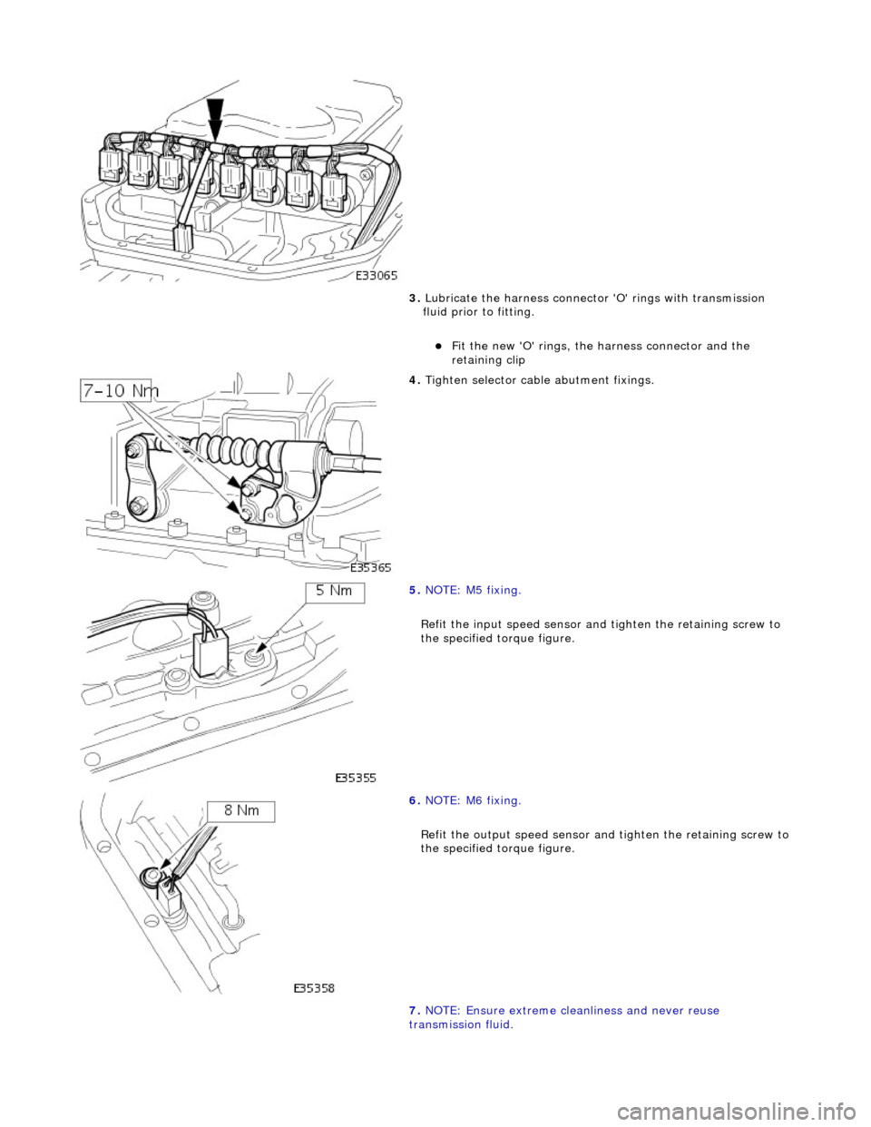
3. Lubricate the harness connector 'O' rings with transmission
fluid prior to fitting.
Fit the new 'O' rings, the harness connector and the
retaining clip
4. Tighten selector cable abutment fixings.
5. NOTE: M5 fixing.
Refit the input speed sensor and tighten the retaining screw to
the specified torque figure.
6. NOTE: M6 fixing.
Refit the output speed sensor and tighten the retaining screw to
the specified torque figure.
7. NOTE: Ensure extreme clea nliness and never reuse
transmission fluid.
Page 1373 of 2490

Automatic Transmission/Transaxle - 4.0L NA V8 - AJ27/3.2L NA V8 - AJ26
- Turbine Shaft Speed (TSS) Sensor
In-vehicle Repair
Removal
1. Disconnect battery ground cable.
Remove the battery cover.
2. Raise the vehicle on a lift.
2. WARNING: TRANSMISSION FLUID MAY CAUSE
SEVERE BURNS, ENSURE THAT ALL SAFETY PROCEDURES
ARE OBSERVED.
Carefully remove the drain plug and drain the
transmission fluid.
3. Remove the twenty-two bolts which secure the fluid pan.
Remove the fluid pan and all tr aces of gasket material.
4. Remove the input speed sensor.
• NOTE: M5 fixing.
1. Release the screw which secures the input speed sensor bracket and pull the sensor clear.
5. Disconnect the multiplug from the speed sensor.
Page 1374 of 2490

Installation
1.
NOTE: M5 fixing.
Connect the multiplug, install the input speed sensor and
securing bracket. Tighten the screw to the specified torque
figure.
2. NOTE: Ensure extreme clea nliness and never reuse
transmission fluid.
Using a new gasket, install the fl uid pan and tighten the twenty-
two fixings to the specified. torque figure.
3. Connect the battery and fit the battery cover..
Reset the radio and the clock.
4. Refer to (44.24.02) for fluid fill procedure.
Page 1389 of 2490
Automatic Transmission/Transaxle - 4.0L SC V8 - AJ26 - Transmission
Description
Description and Operation
Transmission Assembly
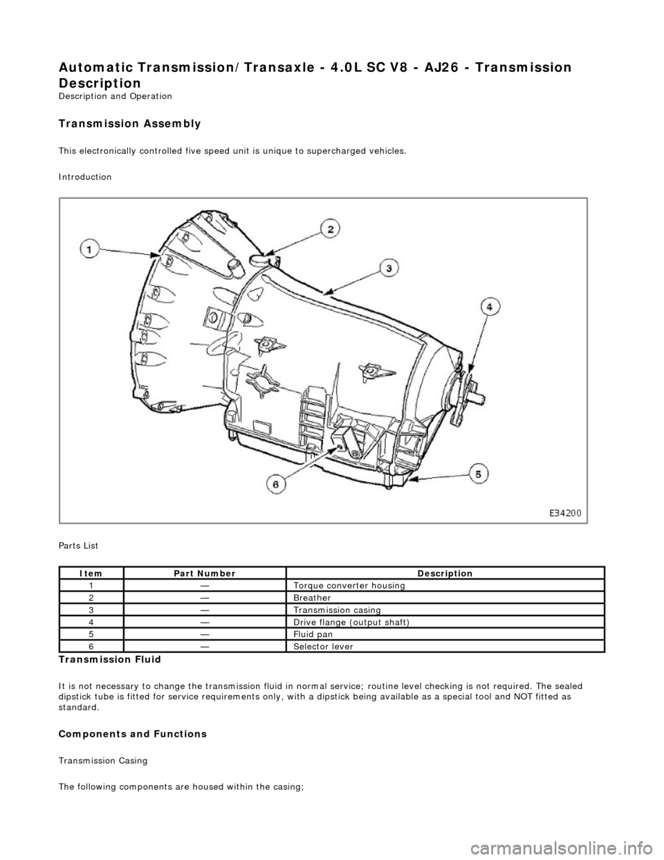
This electronically controlled five speed unit is unique to supercharged vehicles.
Introduction
Parts List
Transmission Fluid
It is not necessary to change the transmis sion fluid in normal service; routine level checking is not required. The sealed
dipstick tube is fitted for service requir ements only, with a dipstick being availa ble as a special tool and NOT fitted as
standard.
Components and Functions
Transmission Casing
The following components are housed within the casing;
ItemPart NumberDescription
1—Torque converter housing
2—Breather
3—Transmission casing
4—Drive flange (output shaft)
5—Fluid pan
6—Selector lever
Page 1390 of 2490
Stator, intermediate and output shafts. Three epicyclic geartrains. Six multi-disc clutch/brake packs. Two freewheels (One-way clutches). Hydraulic pump. Parking lock assembly. Electro-hydraulic control unit. Internal harness and 13 pin connector with bayonet lock.
Hydraulic pump
This engine driven pump is located at the front of the transmission casing and provides pressure for the hydraulic
functions.
Supplies fluid under pressure to the torq ue converter, geartrain, electro-hydraulic control unit and the lubrication
circuit.
Draws fluid from the fluid pa n below the transmission casing, through a filter.
Parking lock
This component prevents movement of th e vehicle by engaging a fixed pawl with the parking lock gear located on the
output shaft. The pawl is engaged by movi ng the gear selector lever to the park (P) position.
Electro-hydraulic control unit
This unit, mounted in the transmission lower case, converts signals, mechanical from the J-gate and electrical from the
TCM, into hydraulic functions.
The following components ar e assembled to the unit:
Selector valve. Shift plate. Control valve - modulating pressure. Control valve - shift pressure. Solenoid valve 1 <-> 2 and 4 <-> 5 shift. Solenoid valve 3 <-> 4 shift. Solenoid valve 2 <-> 3 shift. Solenoid valve - converter lock-up. Speed sensors (2). Temperature sensor.
Speed sensors
There are two speed sensors within the transmission assembly which provide input to the TCM. These inputs, when used in
conjunction with CAN data relative to engine speed (from ECM) and road speed (from ABS), are used to electronically
control the transmission.
Temperature sensor
The output from this sensor allows the TCM to compensate for the affect of fluid temperature on shift time and quality
Control Systems
Hydraulic Control
The selector valve is operated directly by the J-gate and directs fluid flow for P R N D.
Of the four solenoid valves, 3 control shifts and 1 controls converter lock-up. One control valve controls modulating pressure
and the other shift pressure.
Regulating valves are used to maintain/control pressure for lu brication, normal operating functions, and the supply to the
control valves and shift valves.
Page 1391 of 2490
In the event of a system fault, the TCM will adopt 'limp home' mode.
Electrical control
Refer to Section 307-01B.
Transmission Control Components
Transmission Control Module (TCM)
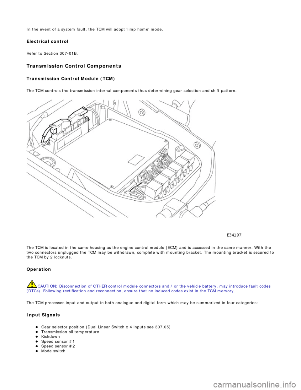
The TCM controls the transmission internal components thus determining gear selection and shift pattern.
The TCM is located in the same housing as the engine control module (ECM) and is accessed in the same manner. With the
two connectors unplugged the TCM may be withdrawn, complete with mounting bracket. The mounting bracket is secured to
the TCM by 2 locknuts.
Operation
CAUTION: Disconnection of OTHER contro l module connectors and / or the vehicle battery, may introduce fault codes
(DTCs). Following rectification and reconnection, ensu re that no induced codes exist in the TCM memory.
The TCM processes input and output in both analogue and di gital form which may be summarized in four categories:
Input Signals
Gear selector position (Dual Linear Switch x 4 inputs see 307.05) Transmission oil temperature Kickdown Speed sensor #1 Speed sensor #2 Mode switch
Page 1392 of 2490
CAN Input Signals
Traction status ABS malfunction ABS status Engine torque status Throttle position Accelerator pedal position Engine torque reduction confirmation Engine speed Engine coolant temperature Cruise status OBDII fault code clear request Throttle malfunction warning RED or AMBER All road wheel speeds Token for network status ECM Token for network status INST Token for network status ABS Diagnostic data in from external device (PDU)
Output Signals
Solenoid valve 1 <-> 2 and 4 <-> 5 shift Solenoid valve 2 <-> 3 shift Solenoid valve 3 <-> 4 shift Solenoid valve converter lock-up clutch Control valve - modulating pressure Control valve - shift pressure
CAN Output Signals
Engine torque reduction request MIL status (whether present DTC should operate MIL) Transmission input speed Transmission output speed Converter slip Kickdown status Gear position (actual) Gear position (selected) Gear selection fault Converter lock-up status Current selected shift map Transmission oil temperature Transmission malfunction Pecus flag (state of current TCM program) Target for next gear position Gear shift torque transfer progress at shift MIL status (response to activate the MIL relevant to a DTC) OBDII fault code clear acknowledgement Transmission DTCs (P codes) Token for network status TCM Diagnostic data out to external device (PDU)
Emergency Running (elect ronic limp-home mode)
The TCM constantly monitors the transmissi on for faults. In the event of a problem the TCM will adopt the limp-home mode, in which the gear currently held remains engaged, until P is selected. The modulati ng and shift pressures will increase to
maximum and converter lock-up will be inhibited.
Following the selection of P , the only ratios available will be 2 (irrespective of forward ratio manual selection) and R .
With the vehicle at rest, the procedure to manually select is as follows:
1. 1. Select P .
Page 1393 of 2490
2.2. Switch OFF the ignition.
3. 3. Wait 10 seconds.
4. 4. Start the engine.
5. 5. Select R (reverse will be selected).
6. 6. Select D ( 2 will be selected).
The limp-home mode will be retained until the fault is remedied or the fault code has been erased. Intermittent faults may
be cleared by cycling the ignition OFF/ON. In certain cases the component may need to be operated before the fault code is
cleared eg. a shift solenoid.
Emergency Running (mechanica l/hydraulic limp-home mode)
Should slip be detected, due to a mechanical failure or loss of pressure, the transmission will either shift to, and hold 3 or
shift to, and hold, the last gear which was known to be alright. This condition may be cleared by cycling the ignition OFF/ON
following mechanical repair.
The operator will be made aware of certain faults by a warning message on th e instrument cluster.
Data concerning OBDII related transmission failures is stored in the ECM for access via the J1962 socket.
Safety Functions
These functions are designed to safeguard against inappropriate actions by the operator as well as system malfunctions.
The electrical and diagnostic system has been designed such that system integrity is protected at all times, the safety
concept being based on th e following three points.
1. 1. The hydraulic system has 'fail-safe' characteristics regardin g its electrical operation, such that should the power
supply be lost to the electro-hydraulic actuators the transmission will initiate a limp-home mode.
2. 2. Recognition of critical shift operation by monitoring the last element in the signal path, ie the solenoid valve, and
checking by means of redundant me asured variables relative to engine, transmission and road speeds.
3. 3. Each time the vehicle is started there is a check on the entire safety hardware and the associated program parts
and signal paths. A malfunction in this part of the system, or triggering of the safety circuit, is communicated to
the operator by a warning messag e on the instrument cluster.
CAUTION: Do not engage R or P with the vehicle in motion.
Should R be engaged with the vehicle in forward motion, the transmission will default to neutral until either the vehicle
speed decreases to 4 mph or D is selected.
Towing
The vehicle may be towed provided that:
Selector in position N Speed < 50 kph Distance < 50 km
System Functions
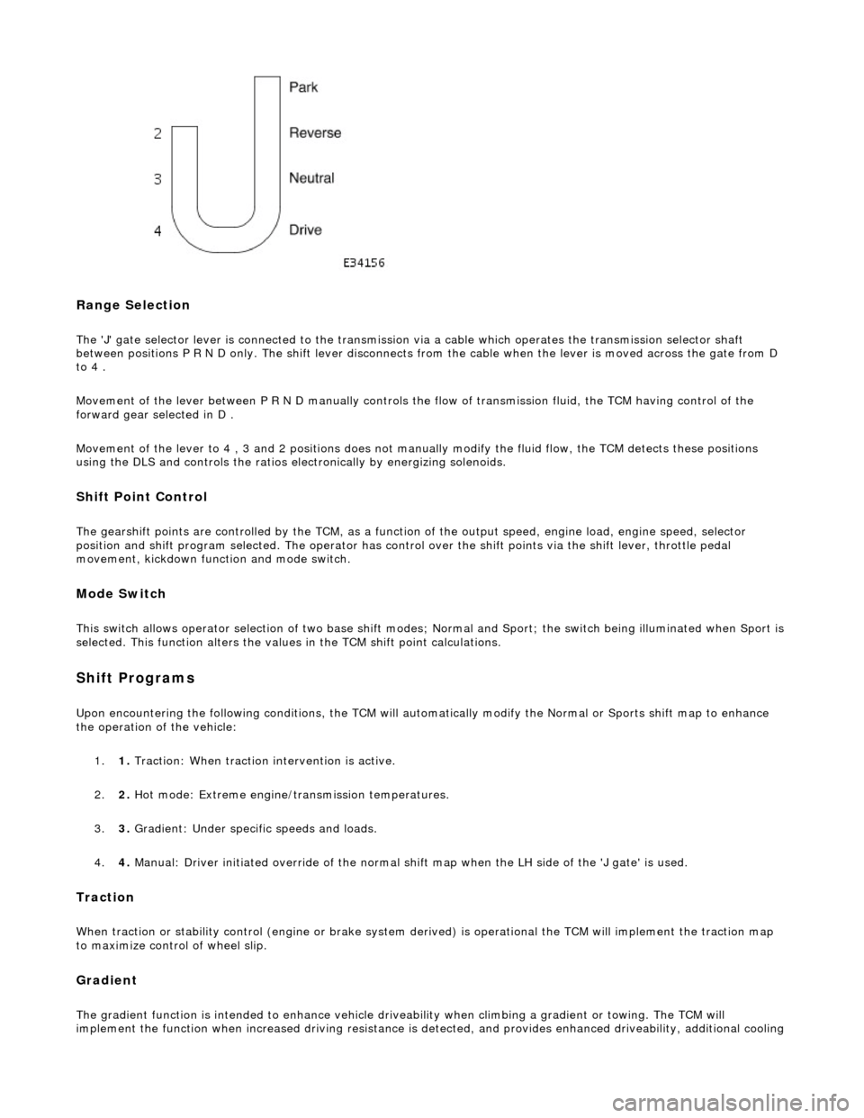
'J' Gate Layout
Page 1394 of 2490
Range Selection
The 'J' gate selector lever is connected to the transmission via a cable which operates the transmission selector shaft
between positions P R N D only. The shift lever disconnects from the cable when the lever is moved across the gate from D
to 4 .
Movement of the lever between P R N D manu ally controls the flow of transmission fluid, the TCM having control of the
forward gear selected in D .
Movement of the lever to 4 , 3 and 2 positions does not manu ally modify the fluid flow, the TCM detects these positions
using the DLS and controls the ratios electronically by energizing solenoids.
Shift Point Control
The gearshift points are controlled by the TCM, as a function of the output speed, engine load, engine speed, selector
position and shift program selected. The operator has control over the shift points via the shift lever, throttle pedal
movement, kickdown function and mode switch.
Mode Switch
This switch allows operator selection of two base shift modes; Normal and Sport; th e switch being illuminated when Sport is
selected. This function alters the values in the TCM shift point calculations.
Shift Programs
Upon encountering the following conditions, the TCM will auto matically modify the Normal or Sports shift map to enhance
the operation of the vehicle:
1. 1. Traction: When traction intervention is active.
2. 2. Hot mode: Extreme engine/transmission temperatures.
3. 3. Gradient: Under specific speeds and loads.
4. 4. Manual: Driver initiated override of the normal shif t map when the LH side of the 'J gate' is used.
Traction
When traction or stability control (engine or brake system de rived) is operational the TCM will implement the traction map
to maximize control of wheel slip.
Gradient
The gradient function is intended to enhance vehicle drivea bility when climbing a gradient or towing. The TCM will
implement the function when increased driving resistance is de tected, and provides enhanced driveability, additional cooling
Page 1396 of 2490
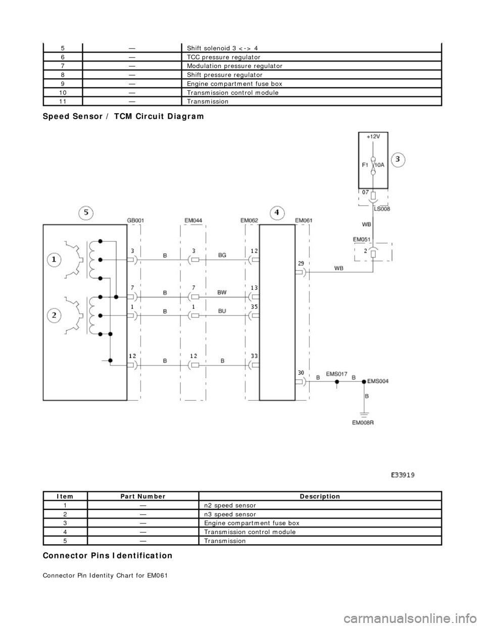
Speed Sensor / TCM Circuit Diagram
Connector Pins Identification
Connector Pin Identity Chart for EM061
5—Shift solenoid 3 <-> 4
6—TCC pressure regulator
7—Modulation pressure regulator
8—Shift pressure regulator
9—Engine compartment fuse box
10—Transmission control module
11—Transmission
ItemPart NumberDescription
1—n2 speed sensor
2—n3 speed sensor
3—Engine compartment fuse box
4—Transmission control module
5—Transmission