speed JAGUAR X308 1998 2.G Workshop Manual
[x] Cancel search | Manufacturer: JAGUAR, Model Year: 1998, Model line: X308, Model: JAGUAR X308 1998 2.GPages: 2490, PDF Size: 69.81 MB
Page 1397 of 2490
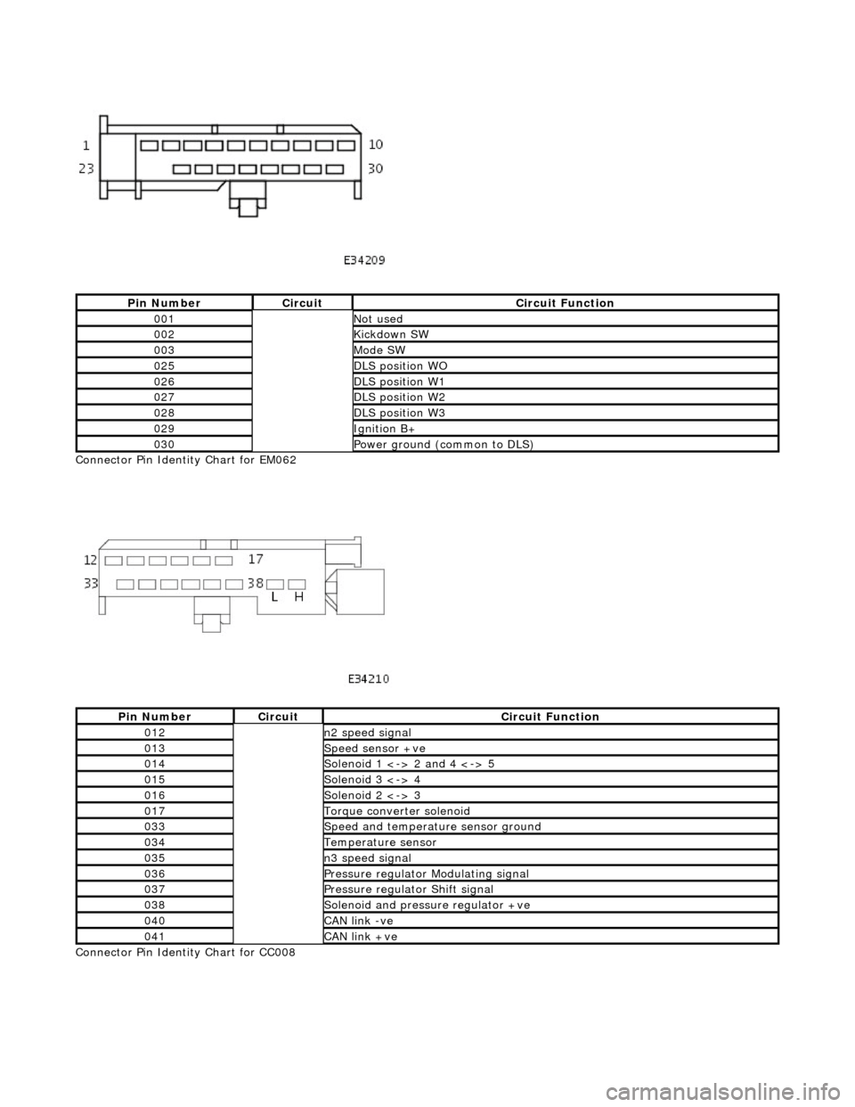
Connector Pin Identity Chart for EM062
Connector Pin Identity Chart for CC008
Pin NumberCircuitCircuit Function
001Not used
002Kickdown SW
003Mode SW
025DLS position WO
026DLS position W1
027DLS position W2
028DLS position W3
029Ignition B+
030Power ground (common to DLS)
Pin NumberCircuitCircuit Function
012n2 speed signal
013Speed sensor +ve
014Solenoid 1 <-> 2 and 4 <-> 5
015Solenoid 3 <-> 4
016Solenoid 2 <-> 3
017Torque converter solenoid
033Speed and temperature sensor ground
034Temperature sensor
035n3 speed signal
036Pressure regulator Modulating signal
037Pressure regulator Shift signal
038Solenoid and pressure regulator +ve
040CAN link -ve
041CAN link +ve
Page 1398 of 2490
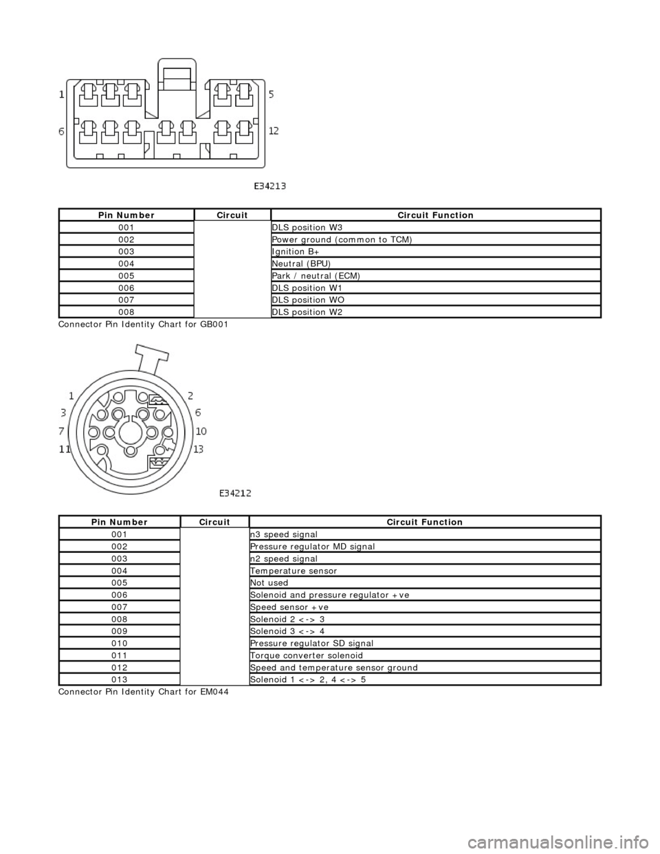
Connector Pin Identity Chart for GB001
Connector Pin Identity Chart for EM044
Pin NumberCircuitCircuit Function
001DLS position W3
002Power ground (common to TCM)
003Ignition B+
004Neutral (BPU)
005Park / neutral (ECM)
006DLS position W1
007DLS position WO
008DLS position W2
Pin NumberCircuitCircuit Function
001n3 speed signal
002Pressure regulator MD signal
003n2 speed signal
004Temperature sensor
005Not used
006Solenoid and pressure regulator +ve
007Speed sensor +ve
008Solenoid 2 <-> 3
009Solenoid 3 <-> 4
010Pressure regulator SD signal
011Torque converter solenoid
012Speed and temperature sensor ground
013Solenoid 1 <-> 2, 4 <-> 5
Page 1399 of 2490

Pin NumberCircuitCircuit Function
001n3 speed signal
002Pressure regulator MD signal
003n2 speed signal
004Temperature sensor
005Solenoid 1 <-> 2, 4 <-> 5
006Solenoid and pressure regulator +ve
007Speed sensor +ve
008Solenoid 2 <-> 3
009Solenoid 3 <-> 4
010Pressure regulator SD signal
011Torque converter solenoid
012Speed and temperature sensor ground
Page 1400 of 2490
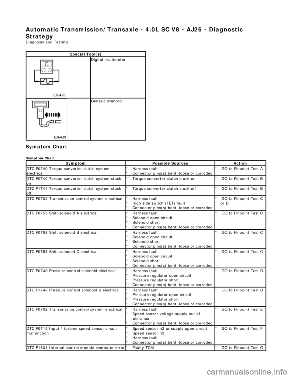
Automatic Transmission/Transaxle - 4.0L SC V8 - AJ26 - Diagnostic
Strategy
Diagnosis and Testing
Symptom Chart
Symptom Chart
Special Tool(s)
Digital multimeter
Generic scantool
SymptomPossible SourcesAction
DTC P0740 Torque converter clutch system
electricalHarness fault
Connector pins(s) bent , loose or corroded
*
*GO to Pinpoint Test A
*
DTC P0740 Torque converter clutch system stuck
onTorque converter clutch stuck on
*GO to Pinpoint Test B
*
DTC P1744 Torque converter clutch system stuck
offTorque converter clutch stuck off
*GO to Pinpoint Test B
*
DTC P0702 Transmission control system electricalHarness fault
High side switch (FET) fault
Connector pins(s) bent , loose or corroded
*
*
*GO to Pinpoint Test C
or D
*
DTC P0753 Shift solenoid A electricalHarness fault
Solenoid open circuit
Solenoid short
Connector pins(s) bent
, loose or corroded
*
*
*
*GO to Pinpoint Test C *
DTC P0758 Shift solenoid B electricalHarness fault
Solenoid open circuit
Solenoid short
Connector pins(s) bent
, loose or corroded
*
*
*
*GO to Pinpoint Test C *
DTC P0763 Shift solenoid C electricalHarness fault
Solenoid open circuit
Solenoid short
Connector pins(s) bent
, loose or corroded
*
*
*
*GO to Pinpoint Test C *
DTC P0748 Pressure control solenoid electricalHarness fault
Pressure regulator open circuit
Pressure regulator short
Connector pins(s) bent
, loose or corroded
*
*
*
*GO to Pinpoint Test D *
DTC P1748 Pressure control solenoid B electricalHarness fault
Pressure regulator open circuit
Pressure regulator short
Connector pins(s) bent
, loose or corroded
*
*
*
*GO to Pinpoint Test D *
DTC P0702 Transmission control system electricalHarness fault
Speed sensor voltage supply out of
tolerance Connector pins(s) bent , loose or corroded
*
*
*GO to Pinpoint Test E
*
DTC P0715 Input / turbine speed sensor circuit
malfunctionSpeed sensor n2 or supply open circuit
Speed sensor n3
Harness fault
Connector pins(s) bent , loose or corroded
*
*
*
*GO to Pinpoint Test F
*
DTC P1601 Internal control module computer errorFaulty TCM
*GO to Pinpoint Test G *
Page 1424 of 2490

With EM062 and GB001 disconnected, measure the
resistance between GB001/012 and EM062/033 1
Is the resistance < 0.5 OHM?
Yes GO to F4
No Inspect EM062, EM044 and GB001 for corrosion, bent /
pushed back pins or locate harness. Repair as necessary
and test the system fo r normal operation.
F4: CHECK SIGNAL CONTINUITY (N2 SPEED SENSOR)
Page 1425 of 2490

With EM062 and GB001 disconnected, measure the
resistance between GB001/003 and EM062/012 1
Is the resistance < 0.5 OHM?
Yes Reconnect GB001
GO to F5
No Inspect EM062, EM044 and GB001 for corrosion, bent /
pushed back pins or locate harness. Repair as necessary
and test the system fo r normal operation.
F5: CHECK SIGNAL CONTINUITY (N3 SPEED SENSOR)
Page 1502 of 2490
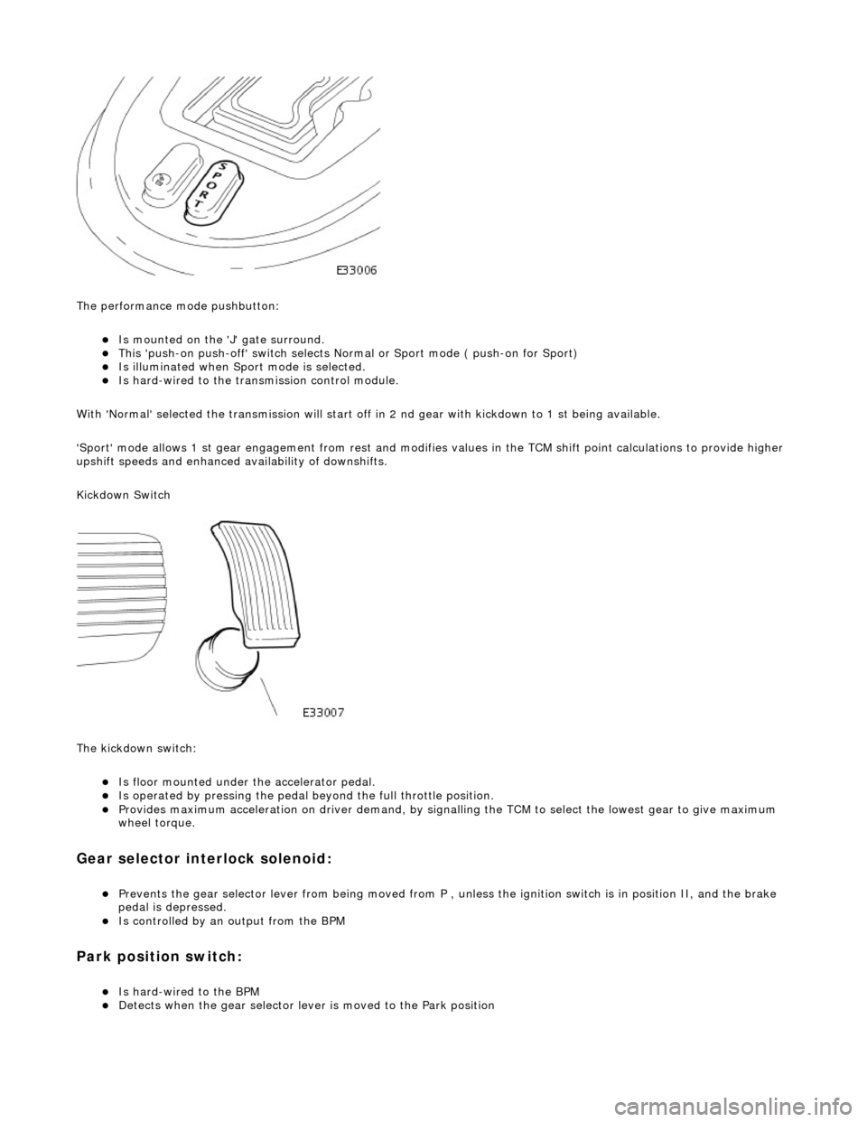
The performance mode pushbutton:
Is mounted on the 'J' gate surround. This 'push-on push-off' swit ch selects Normal or Sport mode ( push-on for Sport) Is illuminated when Sport mode is selected. Is hard-wired to the transmission control module.
With 'Normal' selected the transmissi on will start off in 2 nd gear with kickdown to 1 st being available.
'Sport' mode allows 1 st gear en gagement from rest and modifies values in the TCM shift point calculations to provide higher
upshift speeds and enhanced availability of downshifts.
Kickdown Switch
The kickdown switch:
Is floor mounted under th e accelerator pedal. Is operated by pressing the pedal beyond the full throttle position. Provides maximum acceleration on driver demand, by signalling the TCM to select the lowest gear to give maximum
wheel torque.
Gear selector interlock solenoid:
Prevents the gear selector lever from being moved from P , unless the ignition switch is in position II, and the brake
pedal is depressed.
Is controlled by an output from the BPM
Park position switch:
Is hard-wired to the BPM Detects when the gear selector lever is moved to the Park position
Page 1535 of 2490
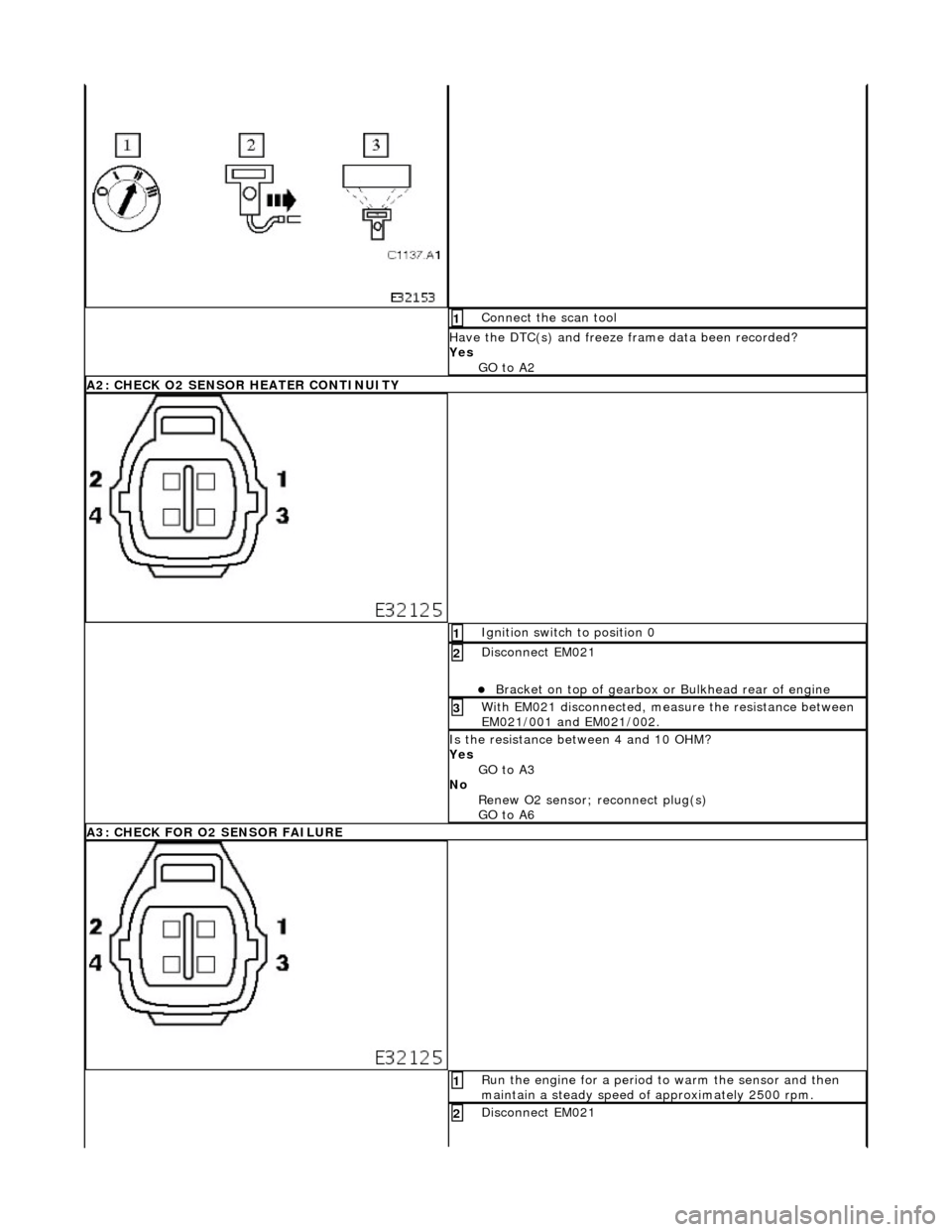
Connect the scan tool 1
Have the DTC(s) and freeze frame data been recorded?
Yes GO to A2
A2: CHECK O2 SENSOR HEATER CONTINUITY
Ignition switch to position 0 1
Disconnect EM021
Bracket on top of gearbox or Bulkhead rear of engine
2
With EM021 disconnected, measure the resistance between
EM021/001 and EM021/002. 3
Is the resistance between 4 and 10 OHM?
Yes
GO to A3
No Renew O2 sensor; reconnect plug(s)
GO to A6
A3: CHECK FOR O2 SENSOR FAILURE
Run the engine for a period to warm the sensor and then
maintain a steady speed of approximately 2500 rpm. 1
Disconnect EM021 2
Page 1547 of 2490

Run the engine for a period to warm the sensor and then
maintain a steady speed of approximately 2500 rpm. 1
Measure the voltage between EM021/003 and EM021/004. 2
Is the voltage between 600mV and 1.0 Volt?
Yes
GO to B5
No Renew O2 sensor, reconnect plug(s).
GO to B8
B5: CHECK FOR O2 SENSOR FAILURE
With the conditions held as B4, suddenly decelerate to idle. 1
Has the voltage dropped to 400mV or less ?
Yes GO to B6
No Renew O2 sensor, reconnect plug(s).
GO to B8
B6: CHECK FOR O2 SENSOR FAILURE
With the conditions held as B5, suddenly accelerate to
approximately 2500 rpm. 1
Has the voltage risen to between 600mV and 1 volt?
Yes
Page 1558 of 2490
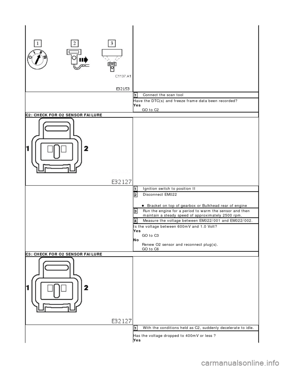
Connect the scan tool 1
Have the DTC(s) and freeze frame data been recorded?
Yes GO to C2
C2: CHECK FOR O2 SENSOR FAILURE
Ignition switch to position II 1
Disconnect EM022
Bracket on top of gearbox or Bulkhead rear of engine
2
Run the engine for a period to warm the sensor and then
maintain a steady speed of approximately 2500 rpm. 3
Measure the voltage between EM022/001 and EM022/002. 4
Is the voltage between 600mV and 1.0 Volt?
Yes
GO to C3
No Renew O2 sensor and reconnect plug(s).
GO to C6
C3: CHECK FOR O2 SENSOR FAILURE
With the conditions held as C2, suddenly decelerate to idle. 1
Has the voltage dropped to 400mV or less ?
Yes