speed JAGUAR X308 1998 2.G Workshop Manual
[x] Cancel search | Manufacturer: JAGUAR, Model Year: 1998, Model line: X308, Model: JAGUAR X308 1998 2.GPages: 2490, PDF Size: 69.81 MB
Page 1570 of 2490

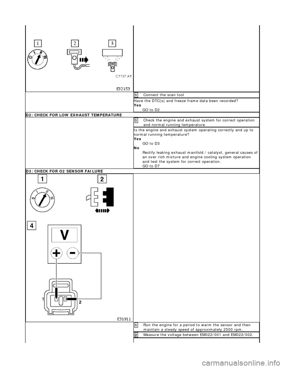
Connect the scan tool 1
Have the DTC(s) and freeze frame data been recorded?
Yes GO to D2
D2: CHECK FOR LOW EXHAUST TEMPERATURE
Check the engine and exhaust system for correct operation
and normal running temperature 1
Is the engine and exhaust system operating correctly and up to
normal running temperature?
Yes GO to D3
No Rectify leaking exhaust manifold / catalyst, general causes of
an over rich mixture and engine cooling system operation
and test the system for correct operation.
GO to D7
D3: CHECK FOR O2 SENSOR FAILURE
Run the engine for a period to warm the sensor and then
maintain a steady speed of approximately 2500 rpm. 1
Measure the voltage between EM022/001 and EM022/002. 2
Page 1586 of 2490

Run the engine for a period to warm the sensor and then
maintain a steady speed of approximately 2500 rpm. 1
With EM023 disconnected, measure the voltage between
EM023/003 and EM023/004. 2
Is the voltage between 600mV and 1.0 Volt?
Yes
GO to E4
No Renew O2 sensor. Reconnect plug(s)
GO to E7
E4: CHECK FOR O2 SENSOR FAILURE
Page 1599 of 2490

Run the engine for a period to warm the sensor and then
maintain a steady speed of approximately 2500 rpm. 1
Measure the voltage between EM023/003 and
EM023/004. 2
Is the voltage between 600mV and 1.0 Volt?
Yes
GO to F5
No Renew O2 sensor. Reconnect plug(s).
GO to F8
F5: CHECK FOR O2 SENSOR FAILURE
With the conditions held as F4, suddenly decelerate to
idle. 1
Has the voltage dropped to 400mV or less ?
Yes GO to F6
No Renew O2 sensor. Reconnect plug(s)
GO to F8
F6: CHECK FOR O2 SENSOR FAILURE
With the conditions held as F5, suddenly accelerate to
approximately 2500 rpm. 1
Has the voltage risen to between 600mV and 1 volt?
Page 1610 of 2490

Connect the scan tool 1
Have the DTC(s) and freeze frame data been recorded?
Yes GO to G2
G2: CHECK FOR O2 SENSOR FAILURE
Run the engine for a period to warm the sensor and then
maintain a steady speed of approximately 2500 rpm. 1
Measure the voltage between EM024/001 and EM024/002. 2
Is the voltage between 600mV and 1.0 Volt?
Yes
GO to G3
No Renew O2 sensor and reconnect plug(s)
GO to G6
G3: CHECK FOR O2 SENSOR FAILURE
Page 1625 of 2490

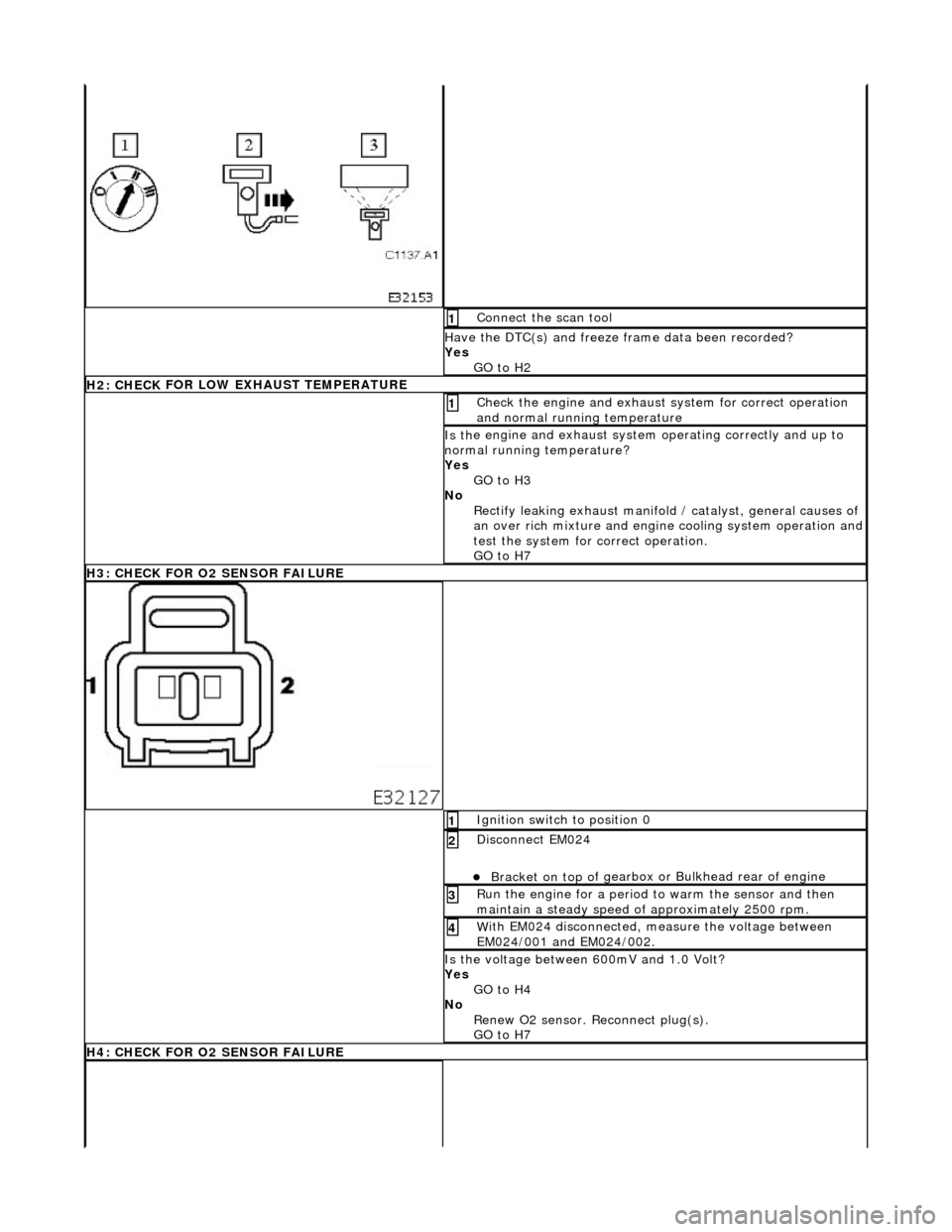
Conne
ct the scan tool
1
Have the DTC(s) and fr
eeze
frame data been recorded?
Yes GO to H2
H2: CHECK
FOR LOW EXHAUST TEMPERATURE
Chec
k the engine and exhaust
system for correct operation
and normal running temperature
1
Is th
e engine and exhaust system operating correctly and up to
normal running temperature?
Yes GO to H3
No Rectify leaking exhaust manifold / catalyst, general causes of
an over rich mixture and engine cooling system operation and
test the system for correct operation.
GO to H7
H
3: CHECK FOR O2 SENSOR FAILURE
I
gnition switch to position 0
1
Di
sconnect EM024
Bracket on top o
f gearbox or
Bulkhead rear of engine
2
R
un the engine for a period to
warm the sensor and then
maintain a steady speed of approximately 2500 rpm.
3
W
ith EM024 disconnected, measure the voltage between
EM024/001 and EM024/002.
4
Is
the voltage between 600mV and 1.0 Volt?
Yes GO to H4
No Renew O2 sensor. Reconnect plug(s).
GO to H7
H
4: CHECK FOR O2 SENSOR FAILURE
Page 1744 of 2490

Speed Control - Speed
Control
D
iagn
osis and Testing
Pri
n
ciples of operation
The s
p
eed (cruise) control sy
stem is activated by an ON/OFF master switch in the J-gate surround, which has an integral
LED to indicate status.
The steering wheel switches allow the driver to set the speed, increase or decrease the selected speed, cancel and resume
the facility without his/her hand ever leaving the steering wheel
The vehicle speed can be increased an d decreased in increments of 2 kmh (1 mph) by briefly pressing the + or - buttons up
to a maximum of five times.
Alternatively, the + or - button can be held until th e desired speed is reached.
The selected speed (by whichever method) w ill be displayed in the message center.
The system will not function at speeds below 26 kmh (16 mph), and can be cancelled from the master switch, the steering
wheel switches, and by depressing th e brake pedal. The system can be overridden by accelerating as normal.
In
spection and Verification
1.
1. Veri fy the customer concern.
2. 2. Vis
ually inspect for obvious signs of mechanical or electrical damage.
3. 3. If an obvious cause for an observed or reported concern is found, correct the cause (if possible) before proceeding
to the next step.
4. 4. If the cause is not visually evident, verify the symptom, check for DTCs and follow the routines in this section.
Vi
sual Inspection Chart
Diagnostic Trouble Code (D
TC) index
MechanicalElectrical
Throttle body mechan
ism
Throttle body actuator
Module Switch(es) Instrument cluster
DTC
De
scr
iption
Possib
l
e Source
Acti
o
n
P0566Speed
c
ontrol
CANCEL
switch ON fault
Speed
control switches internal steering wheel
short circuit to ground
St
eering wheel cassette reel short circuit to
ground
Cassette reel to ECM circ
uit short circuit to
ground
CANCEL
switch failure (stuck ON)
Fo
r
CANCEL switch circuit
tests,GO to Pinpoint Test A.
P0567Speed c
ontrol
RESUME
switch ON fault
Speed
control switches internal steering wheel
short circuit to ground
St
eering wheel cassette reel short circuit to
ground
Cassette reel to ECM circ
uit short circuit to
ground
RESUME swit
ch failure (stuck ON)
For
RESUME switch circuit
tests,GO to Pinpoint Test B.
P0568Spee
d control switch
ground malfunction
Speed
control switches internal steering wheel
open circuit
St
eering wheel cassette reel open circuit or
high resistance
Cassette reel to ECM ci
rcuit open circuit or high
For
ACCEL/DECEL switch circuit
tests,GO to Pinpoint Test C.
Page 1745 of 2490

Pinpoint test
s
re
sistance
ACCEL/DECEL
swi
tch failure
P0569Speed
control
DECEL/SET
(SET-) switch ON fault
Speed
control switches internal steering wheel
short circuit to ground
S
teering wheel cassette
reel short circuit to
ground
Cassette reel
to ECM ci
rcuit short circuit to
ground
DEC
EL/SET
switch failure (stuck ON)
Fo
r
DECEL/SET (SET-) switch
circuit tests,GO to Pinpoint Test D.
P0570Speed
control
ACCEL/SET
(SET+) switch ON fault
Speed
control switches internal steering wheel
short circuit to ground
S
teering wheel cassette
reel short circuit to
ground
Cassette reel
to ECM ci
rcuit short circuit to
ground
ACC
EL/SET
switch failure (stuck ON)
Fo
r
ACCEL/SET circuit tests,GO
to Pinpoint Test E.
P1571Brake sw
itch malfunction
Brake sw
itch to ECM circuit open circuit, short
circuit to ground, high resistance
Brake sw
itch ignition switched ground circuit
open circuit
Brake sw
itch failure
Brake ca
ncel switch to
ECM circuit open circuit,
short circuit to ground, high resistance
Brake ca
ncel switch to speed control switch
circuit open circuit, shor t circuit to ground, high
resistance
Brake ca
ncel switch ignition switched power
supply open circuit
Brake ca
ncel switch failure
Spe
ed control switch failure
For brake swi
tch circuit tests,GO
to Pinpoint Test F.
P
INPOINT TEST A : DTC P0566; SPEED
CONTROL CANCEL SWITCH ON FAULT
WAR
NING: Where tests involve the removal of the steering
wheel, and/or disconnection of air bag connectors, the
procedure for disarming air bags must be followed,
REFER to: Air Bag Supplemental Re straint System (SRS)
(501-20B Supplemental Restra
int System, Description and
Operation).
TE
ST
CONDITIONS
D
ETAILS/RESULTS/ACTIONS
A1: CHECK
THE SPEED CONTROL SWITCHPACK IN
TERNAL CIRCUITS FOR SHORT TO GROUND
Di
sconnect the battery negative terminal.
1
Di
sconnect the speed control switch
pack electrical connector, SW02.
2
R
econnect the battery negative terminal.
3
Meas
ure the resistance between SW
02, pin 06 (BO) and GROUND.
4
Meas
ure the resistance between SW
02, pin 03 (SG) and GROUND.
5
Is either resi
stance
less than 10,000 ohms?
Yes REPAIR the short circuit. For addi tional information, refer to the wiring diagrams. CLEAR the DTC.
TEST the system for normal operation.
No GO to A2
.
A2: CHECK
THE SPEED CONTROL CASSE
TTE REEL FOR SHORT TO GROUND
Di
sconnect the battery negative terminal.
1
D
isconnect the ECM electrical connector, EM11.
2
R
econnect the battery negative terminal.
3
M
easure the resistance between SW02, pin 06 (at the cassette reel side of the connector) and
GROUND.
4
M
easure the resistance between SW02, pin 03 (at the cassette reel side of the connector) and
GROUND.
5
Is either resi
stance
less than 10,000 ohms?
Yes REPAIR the short circuit. For addi tional information, refer to the wiring diagrams. CLEAR the DTC.
TEST the system for normal operation.
Page 1746 of 2490

No
GO to A3.
A3: CHECK THE SPEED CONTRO L CANCEL SWITCH
ACTION
Meas
ure t
he resistance between SW02,
pin 06 (BO) and SW02, pin 03 (SG).
1
Operate
the speed control
CANCEL switch.
2
Do
es the resistance
vary by 680 ohms?
Yes Recheck DTCs. No short found. Po ssible intermittent fault. CLEAR the DTC. TEST the system for
normal operation.
No INSTALL a new speed control switchpack. CLEAR the DTC. TEST the system for normal operation.
PINPOINT TEST B : DTC
P0567; SPEED
CONTROL RESUME SWITCH ON FAULT
WARN
ING: Where tests involve the removal of the steering
wheel, and/or disconnection of air bag connectors, the
procedure for disarming air bags must be followed,
REFER to: Air Bag Supplemental Re straint System (SRS)
(50
1-20B Supplemental Restra
int System, Description and
Operation).
TE S
T
CONDITIONS
D E
TAILS/RESULTS/ACTIONS
B1: CHECK
THE SPEED CONTR
OL SWITCHPACK IN
TERNAL CIRCUITS FOR SHORT TO GROUND
Disc
onnect the speed control switch
pack electrical connector, SW02.
1
Measure t
he resistance between SW
02, pin 06 (BO) and GROUND.
2
Measure t
he resistance between SW
02, pin 03 (SG) and GROUND.
3
Is either resistance le
ss than 10,000 ohms?
Yes REPAIR the short circuit. For addi tional information, refer to the wiring diagrams. CLEAR the DTC.
TEST the system for normal operation.
No GO to B2
.
B2: CHECK THE SPEED CONTR
OL CASSETTE REEL FOR SHORT TO GROUND
M
e
asure the resistance between SW02, pin 06 (at the cassette reel side of the connector) and
GROUND.
1
Me
asure the resistance between SW02, pin 03 (at the cassette reel side of the connector) and
GROUND.
2
Is either resistance le
ss than 10,000 ohms?
Yes REPAIR the short circuit. For addi tional information, refer to the wiring diagrams. CLEAR the DTC.
TEST the system for normal operation.
No GO to B3
.
B3: CHECK THE SPEED CONTR
OL RESUME SWITCH ACTION
Meas
ure t
he resistance between SW02,
pin 06 (BO) and SW02, pin 03 (SG).
1
Operate
the speed control
RESUME switch.
2
Do
es the resistance
vary by 430 ohms?
Yes Recheck DTCs. No short found. Po ssible intermittent fault. CLEAR the DTC. TEST the system for
normal operation.
No INSTALL a new speed control switchpack. CLEAR the DTC. TEST the system for normal operation.
PINPOINT TES
T C : DTC P0568; SPEED CONTROL SWITCH GROUND MALFUNCTION
WAR
N
ING: Where tests involve the removal of the steering
wheel, and/or disconnection of air bag connectors, the
procedure for disarming air bags must be followed,
REFER to: Air Bag Supplemental Re straint System (SRS)
(50
1-20B Supplemental Restra
int System, Description and
Operation).
TE S
T
CONDITIONS
D E
TAILS/RESULTS/ACTIONS
C1: CHECK FOR CONTINUITY T
H
ROUGH STEERING WHEEL
CANCEL AND RESUME SWITCHES (SWITCHES OPEN)
Disc
onnect the speed control switch
pack electrical connector, SW02.
1
Check for c
ontinuity between SW02
, pins 06 (BO) and 03 (SG) wi th the steering wheel switches
inactive.
2
Page 1747 of 2490

Is th
e circuit continuous?
Yes INSTALL a new speed control switchpack. CLEAR the DTC. TEST the system for normal operation.
No GO to C2
.
C2
: CHECK FOR CONTINUITY THROUGH STEERIN
G WHEEL CANCEL SWITCH (SWITCH CLOSED)
Check f
or continuity between SW02, pins 06
(BO) and 03 (SG) with the steering wheel CANCEL
switch operated.
1
Is th
e circuit continuous?
Yes GO to C3
.
No
INSTALL a new speed control switchpack. CLEAR the DTC. TEST the system for normal operation.
C3
: CHECK FOR CONTINUITY THROUGH STEERIN
G WHEEL RESUME SWITCH (SWITCH CLOSED)
Check f
or continuity between SW02, pins 06
(BO) and 03 (SG) with the steering wheel RESUME
switch operated.
1
Is th
e circuit continuous?
Yes GO to C4
.
No
INSTALL a new speed control switchpack. CLEAR the DTC. TEST the system for normal operation.
C4
: CHECK FOR CONTINUITY THROUGH STEERING
WHEEL + AND - SWITCHES (SWITCHES OPEN)
Chec
k for continuity between SW02
, pins 06 (BO) and 04 (SR) with the steering wheel switches
inactive.
1
Is th
e circuit continuous?
Yes INSTALL a new speed control switchpack. CLEAR the DTC. TEST the system for normal operation.
No GO to C5
.
C5
: CHECK FOR CONTINUITY THROUGH STEER
ING WHEEL + SWITCH (SWITCH CLOSED)
Check f
or continuity between SW02, pins 06
(BO) and 04 (SR) with the steering wheel CANCEL
switch operated.
1
Is th
e circuit continuous?
Yes GO to C6
.
No
INSTALL a new speed control switchpack. CLEAR the DTC. TEST the system for normal operation.
C6
: CHECK FOR CONTINUITY THROUGH STEER
ING WHEEL - SWITCH (SWITCH CLOSED)
Check f
or continuity between SW02, pins 06
(BO) and 04 (SR) with the steering wheel CANCEL
switch operated.
1
Is th
e circuit continuous?
Yes GO to C7
.
No
INSTALL a new speed control switchpack. CLEAR the DTC. TEST the system for normal operation.
C7: CHECK THE STEERING
WHEEL CASSETTE
REEL FOR CONTINUITY (CIRCUIT #1)
Di
sconnect the steering wheel cassette electrical connector, SW01.
1
Meas
ure the resistance between SW01, pin 06
and SW02, pin 06 through the cassette reel.
2
Is th
e cassette reel continuous?
Yes GO to C8
.
No
INSTALL a new steering wheel cassette. CLEAR the DTC. TEST the system for normal operation.
C8: CHECK THE STEERING
WHEEL CASSETTE
REEL FOR CONTINUITY (CIRCUIT 2)
Meas
ure the resistance between SW01, pin 03
and SW02, pin 03 through the cassette reel.
1
Is th
e cassette reel continuous?
Yes GO to C9
.
No
INSTALL a new steering wheel cassette. CLEAR the DTC. TEST the system for normal operation.
C9: CHECK THE ECM
TO CASSETTE REEL
CIRCUIT FOR CONTINUITY (CIRCUIT 1)
Di
sconnect the battery negative terminal.
1
D
isconnect the ECM electrical connector, EM11.
2
Meas
ure the resistance between EM11, pin 01 (SR) and SW01, pin 04 (SR).
3
Page 1748 of 2490

Is the res
istance greater than 5 ohms?
Yes REPAIR the circuit. For additional information, refer to the wiring diagrams. CLEAR the DTC. TEST
the system for normal operation.
No GO to C10
.
C10: CHECK T H
E ECM TO CASSETTE REEL
CIRCUIT FOR CONTINUITY (CIRCUIT 2)
Measure t
he resistance between EM11,
pin 05 (SG) and SW01, pin 03 (SG).
1
Is the res
istance greater than 5 ohms?
Yes REPAIR the circuit. For additional information, refer to the wiring diagrams. CLEAR the DTC. TEST
the system for normal operation.
No Contact dealer technical support for advice on possible ECM failure.
PI
NPOINT TEST D : DTC P0
569; SPEED CONTROL DECEL/SET- SWITCH ON FAULT
WARN
ING: Where tests involve the removal of the steering
wheel, and/or disconnection of air bag connectors, the
procedure for disarming air bags must be followed,
REFER to: Air Bag Supplemental Re straint System (SRS)
(50
1-20B Supplemental Restra
int System, Description and
Operation).
TE S
T
CONDITIONS
D E
TAILS/RESULTS/ACTIONS
D1: CHECK
THE SPEED CONTROL SWITCHPACK IN
TERNAL CIRCUITS FOR SHORT TO GROUND
Disc
onnect the speed control switch
pack electrical connector, SW02.
1
Measure t
he resistance between SW
02, pin 06 (BO) and GROUND.
2
Measure t
he resistance between SW
02, pin 04 (SR) and GROUND.
3
Is either resistance le
ss than 10,000 ohms?
Yes REPAIR the short circuit. For addi tional information, refer to the wiring diagrams. CLEAR the DTC.
TEST the system for normal operation.
No GO to D2
.
D2: CHECK
THE SPEED CONTROL CASSE
TTE REEL FOR SHORT TO GROUND
Me
asure the resistance between SW02, pin 06 (at the cassette reel side of the connector) and
GROUND.
1
M e
asure the resistance between SW02, pin 04 (at the cassette reel side of the connector) and
GROUND.
2
Is either resi stance le
ss than 10,000 ohms?
Yes REPAIR the short circuit. For addi tional information, refer to the wiring diagrams. CLEAR the DTC.
TEST the system for normal operation.
No GO to D3
.
D3: CHECK
THE SPEED CONTROL DECEL/SET- SWITCH ACTION
Meas
ure t
he resistance between SW02,
pin 06 (BO) and SW02, pin 04 (SR).
1
Operate
the speed control
DECEL/SET- switch.
2
Do
es the resistance
vary by 680 ohms?
Yes Recheck DTCs. No short found. Po ssible intermittent fault. CLEAR the DTC. TEST the system for
normal operation.
No INSTALL a new speed control switchpack. CLEAR the DTC. TEST the system for normal operation.
PINPOI
NT TEST E : DTC P0570; SPEED CONTROL "ACCEL/SET+" SWITCH "ON" FAULT
WAR
N
ING: Where tests involve the removal of the steering
wheel, and/or disconnection of air bag connectors, the
procedure for disarming air bags must be followed,
REFER to: Air Bag Supplemental Re straint System (SRS)
(50
1-20B Supplemental Restra
int System, Description and
Operation).
TE S
T
CONDITIONS
D E
TAILS/RESULTS/ACTIONS
E1
: CHECK THE SPEED CONTROL
SWITCHPACK IN
TERNAL CIRCUITS FOR SHORT TO GROUND