battery JAGUAR X308 1998 2.G Workshop Manual
[x] Cancel search | Manufacturer: JAGUAR, Model Year: 1998, Model line: X308, Model: JAGUAR X308 1998 2.GPages: 2490, PDF Size: 69.81 MB
Page 1085 of 2490
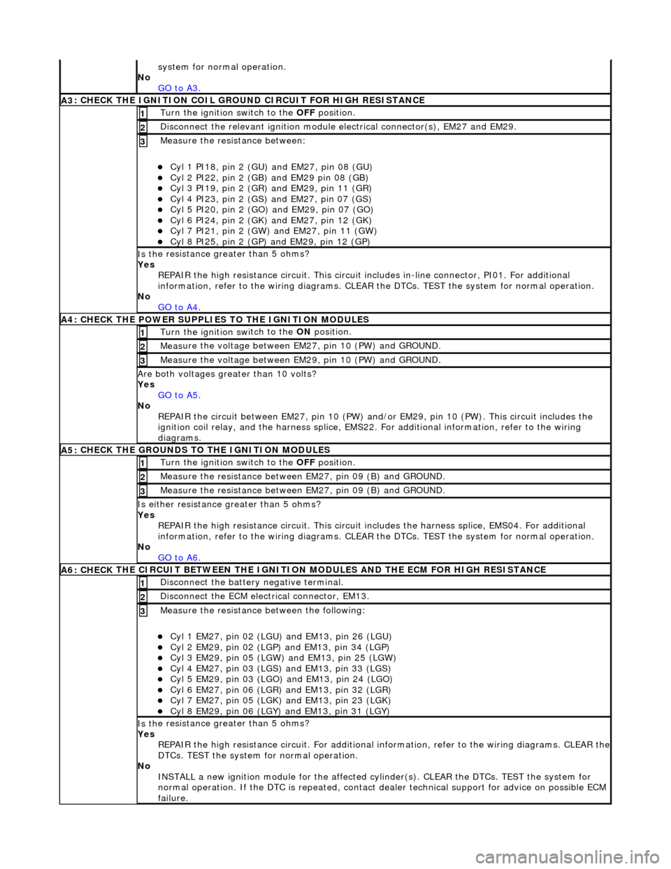
system fo
r normal operation.
No GO to A3
.
A3
: CHECK THE IGNITION COIL GROUND CIRCUIT FOR HIGH RESISTANCE
Turn the ignition swi
tch to the OFF
position.
1
Disc
onnect the relevant ignition module
electrical connector(s), EM27 and EM29.
2
Meas
ure the resistance between:
пЃ¬Cy
l 1 PI18, pin 2 (GU) and EM27, pin 08 (GU)
пЃ¬Cy
l 2 PI22, pin 2 (GB) and EM29 pin 08 (GB)
пЃ¬Cy
l 3 PI19, pin 2 (GR) and EM29, pin 11 (GR)
пЃ¬Cy
l 4 PI23, pin 2 (GS)
and EM27, pin 07 (GS)
пЃ¬Cy
l 5 PI20, pin 2 (GO) and EM29, pin 07 (GO)
пЃ¬Cy
l 6 PI24, pin 2 (GK) and EM27, pin 12 (GK)
пЃ¬Cy
l 7 PI21, pin 2 (GW) and EM27, pin 11 (GW)
пЃ¬Cy
l 8 PI25, pin 2 (GP) an
d EM29, pin 12 (GP)
3
Is th
e resistance greater than 5 ohms?
Yes REPAIR the high resistance circui t. This circuit includes in-line connector, PI01. For additional
information, refer to the wiring diagrams. CLEAR the DTCs. TEST the system for normal operation.
No GO to A4
.
A4:
CHECK THE POWER SUPPLIES TO THE IGNITION MODULES
Turn the ignition swi
tch to the ON
position.
1
Meas
ure the voltage between EM27, pin 10 (PW) and GROUND.
2
Meas
ure the voltage between EM29, pin 10 (PW) and GROUND.
3
Are both
voltages greater than 10 volts?
Yes GO to A5
.
No
REPAIR the circuit between EM27, pin 10 (PW) and/or EM29, pin 10 (PW). This circuit includes the
ignition coil relay, and the harness splice, EMS22. For additional information, refer to the wiring
diagrams.
A5:
CHECK THE GROUNDS TO THE IGNITION MODULES
Turn the ignition swi
tch to the OFF
position.
1
Meas
ure the resistance between EM27, pin 09 (B) and GROUND.
2
Meas
ure the resistance between EM27, pin 09 (B) and GROUND.
3
Is either resi
stance
greater than 5 ohms?
Yes REPAIR the high resistance circui t. This circuit includes the harness splice, EMS04. For additional
information, refer to the wiring diagrams. CLEAR the DTCs. TEST the system for normal operation.
No GO to A6
.
A6: CHECK
THE CIRCUIT BETWEEN THE IGNITION
MODULES AND THE ECM FOR HIGH RESISTANCE
Di
sconnect the battery negative terminal.
1
D
isconnect the ECM electrical connector, EM13.
2
Meas
ure the resistance between the following:
пЃ¬Cy
l 1 EM27, pin 02 (LGU) and EM13, pin 26 (LGU)
пЃ¬Cy
l 2 EM29, pin 02 (LGP) and EM13, pin 34 (LGP)
пЃ¬Cy
l 3 EM29, pin 05 (LGW) and EM13, pin 25 (LGW)
пЃ¬Cy
l 4 EM27, pin 03 (LGS) and EM13, pin 33 (LGS)
пЃ¬Cy
l 5 EM29, pin 03 (LGO) and EM13, pin 24 (LGO)
пЃ¬Cy
l 6 EM27, pin 06 (LGR) and EM13, pin 32 (LGR)
пЃ¬Cy
l 7 EM27, pin 05 (LGK) and EM13, pin 23 (LGK)
пЃ¬Cy
l 8 EM29, pin 06 (LGY) and EM13, pin 31 (LGY)
3
Is th
e resistance greater than 5 ohms?
Yes REPAIR the high resistance circuit. For additional information, refer to the wiring diagrams. CLEAR the
DTCs. TEST the system for normal operation.
No INSTALL a new ignition module for the affected cy linder(s). CLEAR the DTCs. TEST the system for
normal operation. If the DTC is re peated, contact dealer technical support for advice on possible ECM
failure.
Page 1087 of 2490
Engine Igni
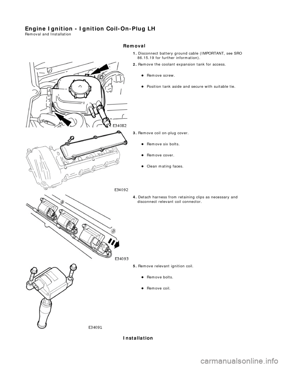
tion - Ignition Coil-On-Plug LH
Re
moval and Installation
Remov
al
Installation
1. Disc
onnect battery ground cable (IMPORTANT, see SRO
86.15.19 for further information).
2. Re
move the coolant expansion tank for access.
пЃ¬R
emove screw.
пЃ¬Position tank aside an
d secu
re with suitable tie.
3. Re
move coil on-plug cover.
пЃ¬R
emove six bolts.
пЃ¬R
emove cover.
пЃ¬Cle
an mating faces.
4. D
etach harness from retain
ing clips as necessary and
disconnect relevant coil connector.
5. R
emove relevant ignition coil.
пЃ¬Re
move bolts.
пЃ¬Re
move coil.
Page 1089 of 2490
Engine Igni
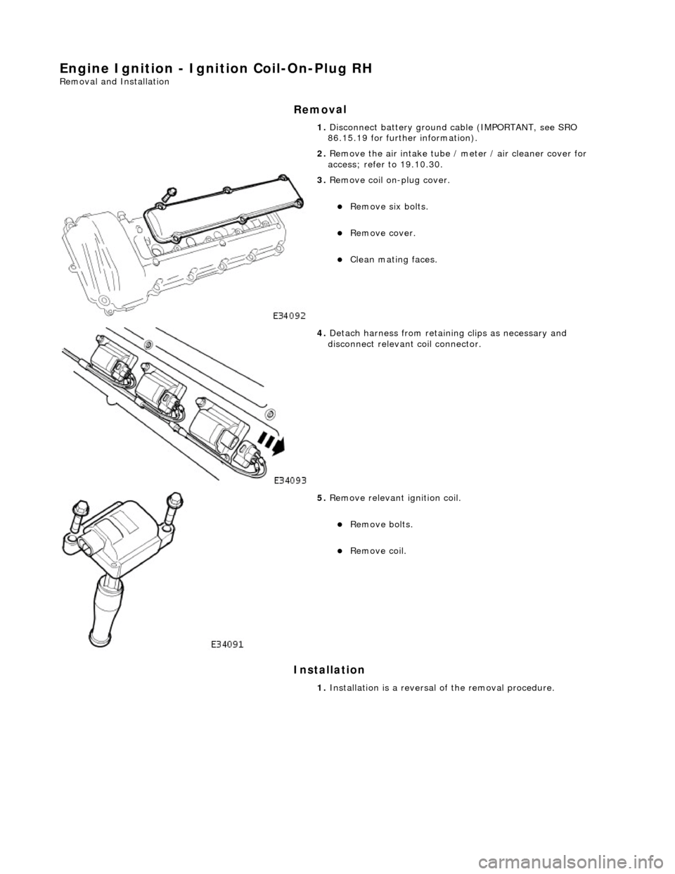
tion - Ignition Coil-On-Plug RH
Re
moval and Installation
Remov
al
Installation
1. Disc
onnect battery ground cable (IMPORTANT, see SRO
86.15.19 for further information).
2. Remove the air intake tube / meter / air cleaner cover for
access; refer to 19.10.30.
3. Re
move coil on-plug cover.
пЃ¬R
emove six bolts.
пЃ¬R
emove cover.
пЃ¬Cle
an mating faces.
4. D
etach harness from retain
ing clips as necessary and
disconnect relevant coil connector.
5. R
emove relevant ignition coil.
пЃ¬Re
move bolts.
пЃ¬Re
move coil.
1. Installation is a reversal of the removal procedure.
Page 1091 of 2490
Engine Igni
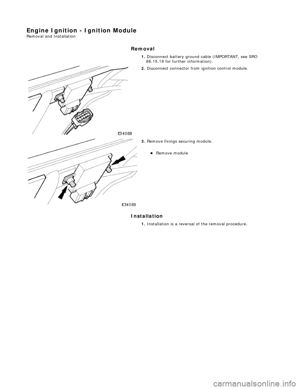
tion - Ignition Module
Re
moval and Installation
Remov
al
Installation
1.
Disc
onnect battery ground cable (IMPORTANT, see SRO
86.15.19 for further information).
2. Disc
onnect connector from ignition control module.
3. Re
move fixings securing module.
пЃ¬Re
move module
1. Installation is a reversal of the removal procedure.
Page 1092 of 2490
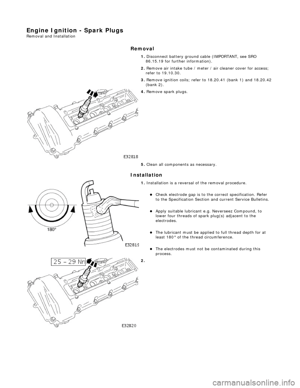
Engine Ignition - Spark
Plugs
Re
mo
val and Installation
Remov
a
l
Installation
1.
Disc onne
ct battery ground cable (IMPORTANT, see SRO
86.15.19 for further information).
2. Remove air intake tube / meter / air cleaner cover for access;
refer to 19.10.30.
3. Remove ignition coils; refer to 18.20.41 (bank 1) and 18.20.42
(bank 2).
4. Re
move spark plugs.
5. Clean all components as necessary.
1. Installation
is a reversal
of the removal procedure.
пЃ¬Check ele
ctrode gap is to the
correct specification. Refer
to the Specification Section and current Service Bulletins.
пЃ¬Apply su
itable lubricant e.
g. Neverseez Compound, to
lower four threads of spark plug(s) adjacent to the
electrodes.
пЃ¬The lubrican t must be applied
to full thread depth for at
least 180В° of the thread circumference.
пЃ¬T h
e electrodes must not be
contaminated during this
process.
2.
Page 1096 of 2490
RE
PAIR the circuit between the EGR valve and battery. This circuit includes the EMS relay and the
EMS fuse box. For additional info rmation, refer to the wiring diagrams. CLEAR the DTC. TEST the
system for normal operation.
No GO to A2
.
A2: CHECK THE EGR VALVE COIL WIND
INGS FOR CONTINUITY
Meas
ure t
he resistance between pins 04 and 06 of the EGR valve.
1
Meas
ure t
he resistance between pins 01 and 03 of the EGR valve.
2
Is either resi
stance
greater
than 80 ohms?
Yes INSTALL a new EGR valve.
REFER to Exhaust Gas Recirculation (EGR) Valve
- in thi
s section.
CLEAR the DTC. TEST the syst em for normal operation.
No GO to A3
.
A3: CHECK THE EGR VALVE COIL WINDINGS TO
POWER SUPPLY CIRCUIT FOR CONTINUITY
Meas
ure t
he resistance between pins 02 and 03 of the EGR valve.
1
Meas
ure t
he resistance between pins 05 and 06 of the EGR valve.
2
Is either resi
stance greater
than 80 ohms?
Yes INSTALL a new EGR valve.
REFER to Exhaust Gas Recirculation (EGR) Valve
- in thi
s section.
CLEAR the DTC. TEST the syst em for normal operation.
No GO to A4
.
A4: CHECK THE EGR VALVE T
O ECM
CIRCUITS FOR HIGH RESISTANCE
Disc
onnect the battery negative terminal.
Vehicles with AJ26 engine:
пЃ¬D i
sconnect the ECM electrical connector, EM12
пЃ¬Meas
ure t
he resistance between the following:
пЃ¬PI34, pin
0
4 (YU) and EM12, pin 01 (YU)
пЃ¬PI34,
pi
n 01 (YG) and EM12, pin 02 (YG)
пЃ¬PI34, pin
0
6 (YN) and EM12, pin 03 (YN)
пЃ¬PI34,
pi
n 03 (YR) and EM12, pin 04 (YR)
Vehicles with AJ27 engine:
пЃ¬D i
sconnect the ECM electrical connector, EM85
пЃ¬Meas
ure t
he resistance between the following:
пЃ¬PI34, pin
0
4 (YU) and EM85, pin 03 (YU)
пЃ¬PI34, pi
n 01 (YG) and EM85, pin 04 (YG)
пЃ¬PI34, pi
n 06 (YR) and EM85, pin 09 (YR)
пЃ¬PI34, pi
n 03 (YR) and EM85, pin 10 (YR)
1
Are an
y of the resistances greater than 5 ohms?
Yes REPAIR the high resistance circui t. For additional information, refer to the wiring diagrams. CLEAR
the DTC. TEST the system for normal operation.
No GO to A5
.
A5: CHECK THE EGR VALVE T
O ECM CIRCUITS FOR SHORT TO HIGH VOLTAGE
R
e
connect the battery negative terminal.
1
Meas
ure t
he voltage between the following:
пЃ¬PI34, pin
0
4 (YU) and GROUND
пЃ¬PI34, pin
0
1 (YG) and GROUND
пЃ¬PI34, pin
0
6 (YN) and GROUND
пЃ¬PI34, pin
0
3 (YR) and GROUND
2
Are any of th
e volt
ages greater than 3 volts?
Yes REPAIR the short circuit. For addi tional information, refer to the wiring diagrams. CLEAR the DTC.
TEST the system for normal operation.
No
Page 1120 of 2490
Intake Air Distribution and Filtering - Charge Air Cooler LH
Remo
val and Installation
Remov
a
l
Installation
1. Disc onne
ct battery ground cable (IMPORTANT, see SRO
86.15.19 for further information).
2. Drain radiator coolant; refer to 26.10.01.
3. Remove air cleaner cover / intake assembly; refer to 19.10.30.
4. Remove throttle body; refer to 19.70.04.
5. Remove exhaust gas re-circulation valve (EGR) if installed;
refer to 17.45.01.
6. Remove throttle intake elbo w; refer to (SC) 19.70.28.
7. Remove supercharger outlet duct; refer to 18.50.16.
8. Remove coolant outlet pipe; refe r to operation (SC) 26.31.08.
9. Remove supercharger drive belt; refer to 18.50.08.
10. Remove supercharger; refer to operation 18.50.15.
11. Detach engine harness retaining clip from rear of charge air
cooler.
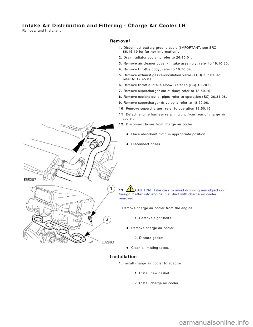
12. Di
sconnect hoses from charge air cooler.
пЃ¬Pla
ce absorbent cloth in appropriate position.
пЃ¬Di
sc
onnect hoses.
13 .
CAUTI
ON: Take care to avoi
d dropping any objects or
foreign matter into engine inle t duct with charge air cooler
removed.
Remove charge air cooler from the engine.
1. Remove eight bolts.
пЃ¬Remove charge air cooler.
2
. Discard gasket.
пЃ¬Cle
a
n all mating faces.
1.
Install ch
arge air
cooler to adaptor.
1. Install new gasket.
2. Install charge air cooler.
Page 1121 of 2490
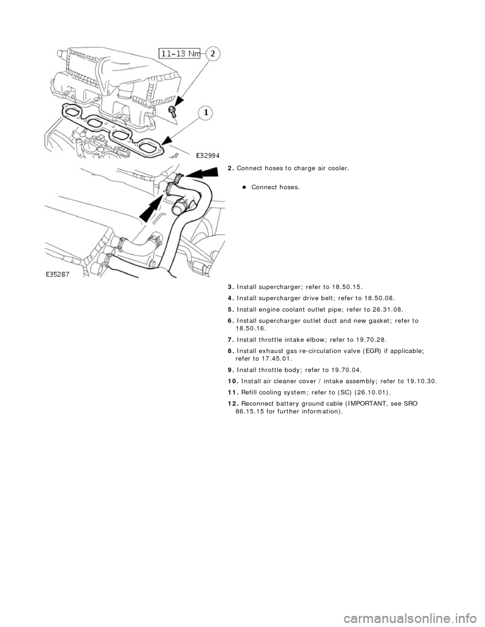
2.
Conne
ct hoses to charge air cooler.
пЃ¬Conne
ct hoses.
3. Install supercharger; refer to 18.50.15.
4. Install supercharger driv e belt; refer to 18.50.08.
5. Install engine coolant outlet pipe; refer to 26.31.08.
6. Install supercharger outlet du ct and new gasket; refer to
18.50.16.
7. Install throttle intake elbow; refer to 19.70.28.
8. Install exhaust gas re-circulation valve (EGR) if applicable;
refer to 17.45.01.
9. Install throttle body ; refer to 19.70.04.
10. Install air cleaner cover / intake assembly; re fer to 19.10.30.
11. Refill cooling system; refer to (SC) (26.10.01).
12. Reconnect battery ground cable (IMPORTANT, see SRO
86.15.15 for further information).
Page 1122 of 2490
Intake Air Distribution and Filtering - Charge Air Cooler RH
Remo
val and Installation
Remov
a
l
Installation
1. Disc onne
ct battery ground cable (IMPORTANT, see SRO
86.15.19 for further information).
2. Drain radiator coolant; refer to 26.10.01.
3. Remove air cleaner cover / intake assembly; refer to 19.10.30.
4. Remove throttle body; refer to 19.70.04.
5. Remove exhaust gas re-circulation valve (EGR) if installed;
refer to 17.45.01.
6. Remove throttle intake elbo w; refer to (SC) 19.70.28.
7. Remove supercharger outlet duct; refer to 18.50.16.
8. Remove coolant outlet pipe; refe r to operation (SC) 26.31.08.
9. Remove supercharger drive belt; refer to 18.50.08.
10. Remove supercharger; refer to operation 18.50.15.
11. Remove intake air temperatur e sensor 2 from charge air
cooler; refer to 18.30.52.
12. Detach engine harness retaining clip from rear of charge air
cooler.
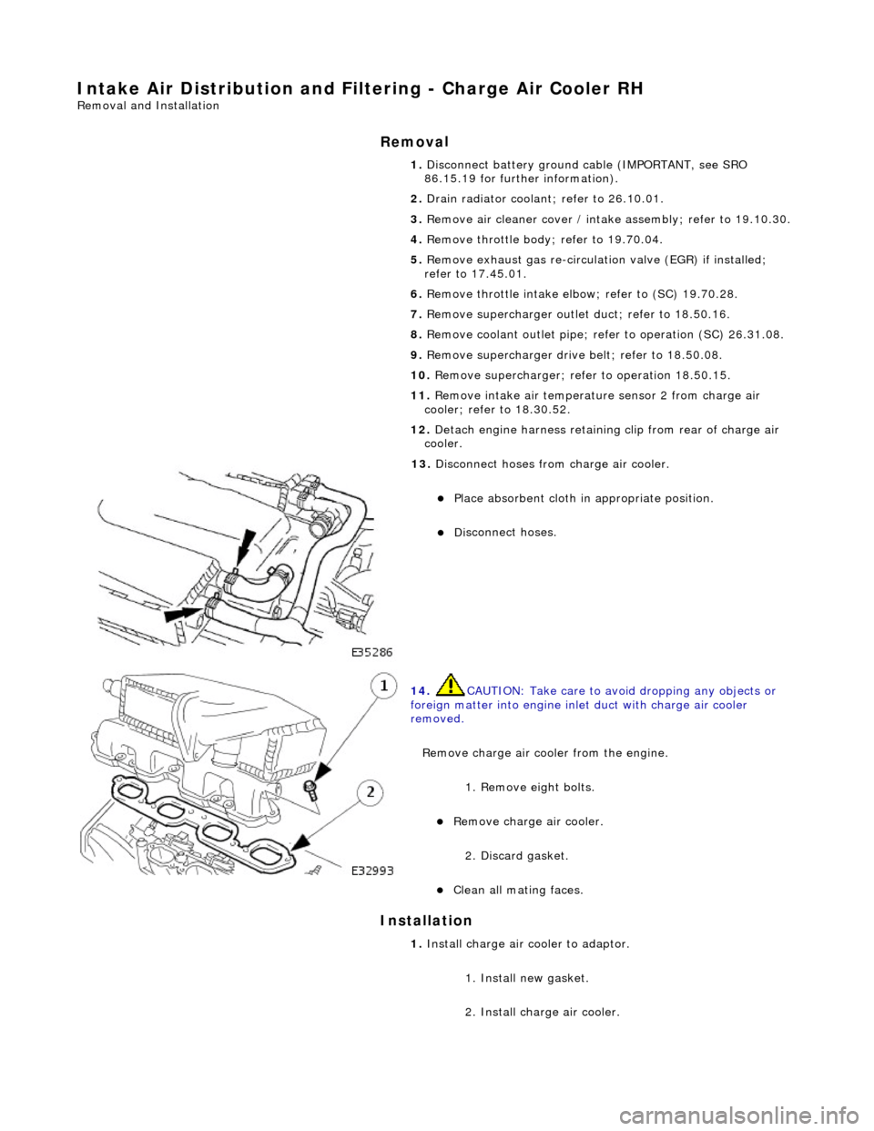
13. Di
sconnect hoses from charge air cooler.
пЃ¬Pla
ce absorbent cloth in appropriate position.
пЃ¬Di
sc
onnect hoses.
14 . CAUTI
ON: Take care to avoi
d dropping any objects or
foreign matter into engine inle t duct with charge air cooler
removed.
Remove charge air cooler from the engine. 1. Remove eight bolts.
пЃ¬Remove charge air cooler.
2
. Discard gasket.
пЃ¬Cle
a
n all mating faces.
1.
Install ch arge air
cooler to adaptor.
1. Install new gasket.
2. Install charge air cooler.
Page 1123 of 2490
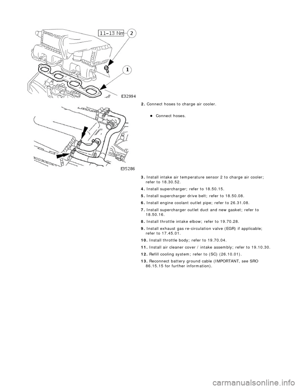
2.
Conne
ct hoses to charge air cooler.
пЃ¬Conne
ct hoses.
3. Install intake air te mperature sensor 2 to charge air cooler;
refer to 18.30.52.
4. Install supercharger; refer to 18.50.15.
5. Install supercharger driv e belt; refer to 18.50.08.
6. Install engine coolant outlet pipe; refer to 26.31.08.
7. Install supercharger outlet du ct and new gasket; refer to
18.50.16.
8. Install throttle intake elbow; refer to 19.70.28.
9. Install exhaust gas re-circulation valve (EGR) if applicable;
refer to 17.45.01.
10. Install throttle body; refer to 19.70.04.
11. Install air cleaner cover / intake assembly; re fer to 19.10.30.
12. Refill cooling system; refer to (SC) (26.10.01).
13. Reconnect battery ground cable (IMPORTANT, see SRO
86.15.15 for further information).