ECO mode JAGUAR X308 1998 2.G User Guide
[x] Cancel search | Manufacturer: JAGUAR, Model Year: 1998, Model line: X308, Model: JAGUAR X308 1998 2.GPages: 2490, PDF Size: 69.81 MB
Page 1194 of 2490
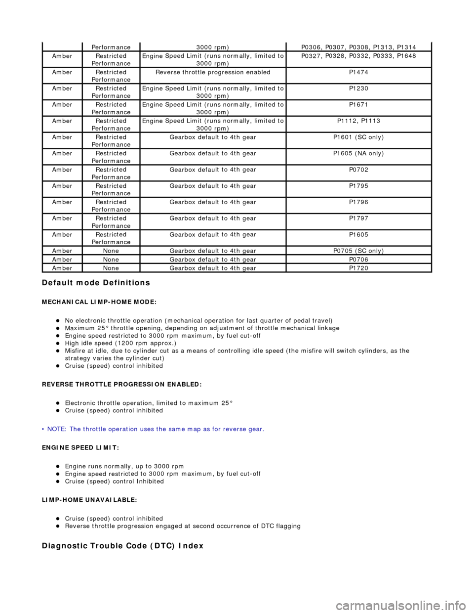
Default mode Definitions
MECHANIC
AL LIMP-HOME MODE:
No elec
tronic throttle operation (mechanical
operation for last quarter of pedal travel)
Ma
ximum 25° throttle opening,
depending on adjustment of th rottle mechanical linkage
Engine speed restri
cted to 3000
rpm maximum, by fuel cut-off
High i
dle speed (1200 rpm approx.)
Misfire
at idle, due
to cylinder cut as a means of control
ling idle speed (the misfire will switch cylinders, as the
strategy varies th e cylinder cut)
Cruise (speed) contr
o
l inhibited
REVERSE THROTTLE PROGRESSION ENABLED:
Elec
tronic throttle operation, limited to maximum 25°
Cruise (speed) contr
o
l inhibited
• NOTE: The throttle oper ation uses the same map as for reverse gear.
ENGINE SPEED LIMIT:
Engine runs
normally, up to 3000 rpm
Engine
speed restri
cted to 3000
rpm maximum, by fuel cut-off
Cruise (speed) contr o
l Inhibited
LIMP-HOME UNAVAILABLE:
Cruise (speed) contro
l inhibited
R
e
verse throttle pr
ogression engaged at second occurrence of DTC flagging
Diagnostic Trouble Code (D TC) Index
Performance3000
rpm)
P03
06,
P0307, P0308, P1313, P1314
Ambe
rRestri
cted
Performance
Engine
Speed Limit (runs normally, limited to
3000 rpm)
P03 27,
P0328, P0332, P0333, P1648
Ambe
rRestri
cted
Performance
R e
verse throttle pr
ogression enabled
P1474
AmberRestri
cted
Performance
Engine
Speed Limit (runs normally, limited to
3000 rpm)
P1230
Ambe rRestri
cted
Performance
Engine
Speed Limit (runs normally, limited to
3000 rpm)
P1671
Ambe rRestri
cted
Performance
Engine
Speed Limit (runs normally, limited to
3000 rpm)
P11 12,
P1113
Ambe
rRestri
cted
Performance
Gearbox defau l
t to 4th gear
P1601 (SC on
ly)
AmberRestri
cted
Performance
Gearbox defau l
t to 4th gear
P16
05 (
NA only)
Ambe
rRestri
cted
Performance
Gearbox defau l
t to 4th gear
P0702
Ambe
rRestri
cted
Performance
Gearbox defau l
t to 4th gear
P1795
Ambe
rRestri
cted
Performance
Gearbox defau l
t to 4th gear
P1796
Ambe
rRestri
cted
Performance
Gearbox defau l
t to 4th gear
P1797
Ambe
rRestri
cted
Performance
Gearbox defau l
t to 4th gear
P1605
Ambe
rNoneGearbox defau l
t to 4th gear
P0705 (SC on
ly)
Ambe
rNoneGearbox defau l
t to 4th gear
P0706
Ambe
rNoneGearbox defau l
t to 4th gear
P1720
Page 1263 of 2490
Op
eration
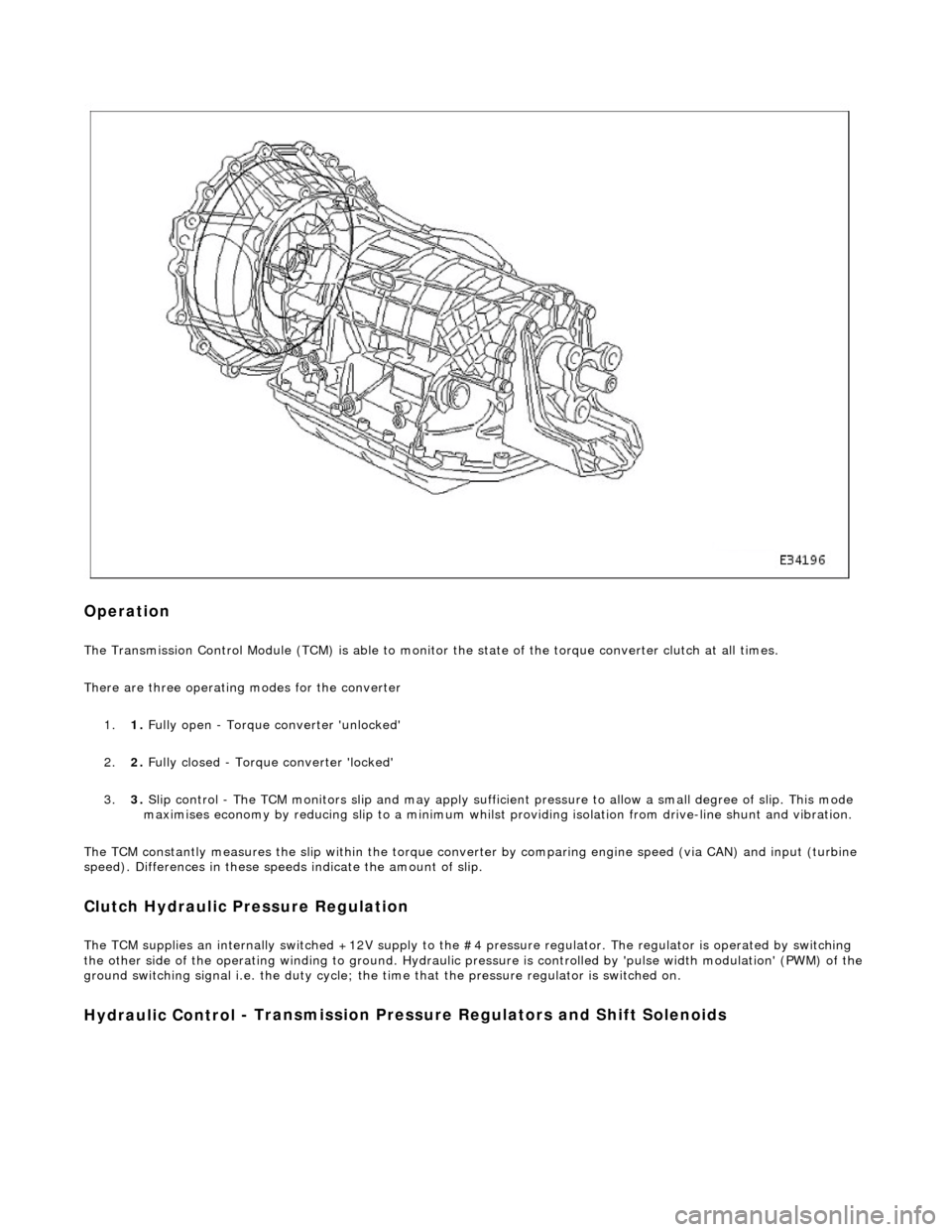
The T
ransmission Control Module (TCM) is
able to monitor the state of the torque converter clut ch at all times.
There are three operating modes for the converter
1. 1. Fully open - Torque converter 'unlocked'
2. 2. Fully closed - Torque converter 'locked'
3. 3. Slip control - The TCM monitors slip and may apply sufficie nt pressure to allow a small degree of slip. This mode
maximises economy by reducing slip to a minimum whilst providing isolation from drive-line shunt and vibration.
The TCM constantly measures the slip within the torque conver ter by comparing engine speed (via CAN) and input (turbine
speed). Differences in these speeds indicate the amount of slip.
Clutch Hydraulic Pressure Regulation
The T
CM supplies an internally switched +1
2V supply to the #4 pressure regulator. The regulator is operated by switching
the other side of the operating winding to ground. Hydraulic pressure is controlled by 'pulse width modulation' (PWM) of the
ground switching signal i.e. the duty cycle; the time that the pressure regulator is switched on.
Hydraulic Control
- Transmission Pre
ssure Regulators an d Shift Solenoids
Page 1269 of 2490
2.2. Check on non-volatile diagnostic memory by wr iting a test pattern and then reading it back.
3. 3. Internal 'watchdog' hardware to check whether the TCM has crashed.
Transmission Control Module Supply Voltage
The TCM monitors battery and igni tion switched supply voltages.
A permanent supply is used to maintain a battery backed 'memor y'. Should this supply be cut, due to battery disconnection
perhaps, the 'adaptive shift' valu es will be lost. This will result in a small reduction in shift quality for a period until th e
adaptions are 're-learned'
The TCM will adopt 'limp home' mode as a result of the supply voltage being >16V or <7V with an engine speed >1600
rpm.
Should the ignition supply be >7V but <9V the TCM will hold the gear that it has currently selected. If after 2.5 seconds,
with the engine speed >1600 rpm, the voltage remains at this level, 'limp home' mode will be adopted. The 2.5 second
delay is built in to prevent reaction to a momentary voltage fluctuation.
Operation
CAUTION: Disconnection of the TCM and / or the vehicle batt ery will cause system adaptions to be lost; this may be
apparent by shift quality degradation. Fo llowing reconnection, a period of 'varied' driving will reinstate adaptions and thus
normal operation. Please ensure that the customer is made aware that the adaption period is variable and may occur after
handover, as the transmission re-learns the prevailing driving style.
• NOTE: Should the TCM fail, please ensure that the control housing cooling fan is operating correctly. Failure of the cooling
fan MUST be rectified before renewing the TCM and details of a fan fa ilure should accompany the returned TCM.
The TCM processes information received in both analogue and digital form, such as:
Transmission input speed Transmission output speed Throttle position Pedal demand Gear selector position Engine torque Engine speed Transmission oil temperature Mode switch
This information is then used by the TC M to control shift energy management and decide which shift program to implement
and which gear to select.
The TCM uses the various sensors and inpu ts to monitor the correct operation of the system an d is programmed to take
default action and inform the operator when a fault occurs.
Safety Functions
The safety functions are designed to safeguard against inappr opriate actions by the operator as well as against system
malfunctions. The system prevents reve rse gear from being engaged at high forward speeds and prevents manual
downshifting at excessive engine speeds; these functions are not operational in mechanical limp-home mode.
The TCM constantly monitors the transmissi on for faults. In the event of a problem the TCM will adopt a 'limp home' mode
in which only P R N D - (selector in D but only fourth gear is enabled) are available. The operator will be made aware of
certain faults by an in strument panel warning.
The electrical and diagnostic system has been designed such that system integrity is protected at all times, the safety
concept being based on th e following three points:
Page 1270 of 2490
1.1. The hydraulic system has 'fail-safe' characteristics regardin g its electrical operation, such that should the power
supply be lost to the electro-hydraulic actuators the transmission will initiate a limp-home mode.
2. 2. Recognition of critical shift operation by monitoring the last element in the signal path, ie the solenoid valve, and
checking by means of redundant me asured variables, ie engine speed, input speed and output speed.
3. 3. Each time the vehicle is started there is a check on the entire safety hardware and the associated program parts
and signal paths. A malfunction in this part of the system, or triggering of the safety circuit, is communicated to
the operator through the illumination of the transmission warning lamp.
TCM Inputs
Input Speed Sensor (Torque Converter Turbine)
The input speed sensor provides the TCM with transmission inpu t shaft speed information. This signal is produced from an
inductive pick-up, generating 30 pulses per revolution.
Transmission Output Speed Sensor
The output speed sensor provides the TCM with transmission ou tput shaft speed information. This signal is produced from
an inductive pick-up, generati ng 36 pulses per revolution.
Transmission Oil Temperature Sensor
A thermistor which provides an electrical indication of the oi l temperature to the TCM. The signal is measured as a voltage
with reference to analog ue ground in the TCM.
Kickdown Switch (where fitted)
Kickdown is intended to provide maximum vehicle acceleration , via the appropriate downshift(s), when the operator uses
full throttle. A kickdown switch provides an electrical signal to the TCM wh en the accelerator pedal is fully pressed. The
switch is normally open, connected to vehicle ground. Should the switch fail the TCM will detect kickdown using the
accelerator pedal position.
Throttle Pedal Stop (where fitted)
This component, used where the kickdown switch is not fitted, limits throttle pedal travel .in the same way. The kickdown
feature is retained, but is controlled by throttle position only. The pedal stop must be set, using the PDU, in the same way
as the kickdown switch to optimize performance.
Mode Selection Switch
The mode selection switch is a two position switch indicati ng to the TCM the current performance mode selected by the
driver. The switch generates a tw o-bit digital input to the TCM.
Rotary Position Switch
The rotary position switch detects the position of the transmis sion selector shaft. The switch is supplied as part of a new
transmission assembly, mounted on the transmission body. The swit ch is used to indicate to the TCM the six positions of the shaft: Park, Reverse, Neutral, Drive, Third and Second. The switch provides a four-bit input to the TCM.
Drive to Fourth Switch
Detects the movement of the selector lever from Drive to Fourth position. The selector cable, and therefore the transmission selector shaft, does not move as the lever is operated between these two positions. The switch is located within the 'J-gate'
assembly, producing a digital output to indicate to the TCM that the lever has moved from D to 4 .
Serial Communications Interfaces
Page 1391 of 2490
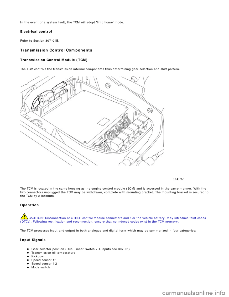
In the event of a system fault, the TCM will adopt 'limp home' mode.
Electrical control
Refer to Section 307-01B.
Transmission Control Components
Transmission Control Module (TCM)
The TCM controls the transmission internal components thus determining gear selection and shift pattern.
The TCM is located in the same housing as the engine control module (ECM) and is accessed in the same manner. With the
two connectors unplugged the TCM may be withdrawn, complete with mounting bracket. The mounting bracket is secured to
the TCM by 2 locknuts.
Operation
CAUTION: Disconnection of OTHER contro l module connectors and / or the vehicle battery, may introduce fault codes
(DTCs). Following rectification and reconnection, ensu re that no induced codes exist in the TCM memory.
The TCM processes input and output in both analogue and di gital form which may be summarized in four categories:
Input Signals
Gear selector position (Dual Linear Switch x 4 inputs see 307.05) Transmission oil temperature Kickdown Speed sensor #1 Speed sensor #2 Mode switch
Page 1393 of 2490
2.2. Switch OFF the ignition.
3. 3. Wait 10 seconds.
4. 4. Start the engine.
5. 5. Select R (reverse will be selected).
6. 6. Select D ( 2 will be selected).
The limp-home mode will be retained until the fault is remedied or the fault code has been erased. Intermittent faults may
be cleared by cycling the ignition OFF/ON. In certain cases the component may need to be operated before the fault code is
cleared eg. a shift solenoid.
Emergency Running (mechanica l/hydraulic limp-home mode)
Should slip be detected, due to a mechanical failure or loss of pressure, the transmission will either shift to, and hold 3 or
shift to, and hold, the last gear which was known to be alright. This condition may be cleared by cycling the ignition OFF/ON
following mechanical repair.
The operator will be made aware of certain faults by a warning message on th e instrument cluster.
Data concerning OBDII related transmission failures is stored in the ECM for access via the J1962 socket.
Safety Functions
These functions are designed to safeguard against inappropriate actions by the operator as well as system malfunctions.
The electrical and diagnostic system has been designed such that system integrity is protected at all times, the safety
concept being based on th e following three points.
1. 1. The hydraulic system has 'fail-safe' characteristics regardin g its electrical operation, such that should the power
supply be lost to the electro-hydraulic actuators the transmission will initiate a limp-home mode.
2. 2. Recognition of critical shift operation by monitoring the last element in the signal path, ie the solenoid valve, and
checking by means of redundant me asured variables relative to engine, transmission and road speeds.
3. 3. Each time the vehicle is started there is a check on the entire safety hardware and the associated program parts
and signal paths. A malfunction in this part of the system, or triggering of the safety circuit, is communicated to
the operator by a warning messag e on the instrument cluster.
CAUTION: Do not engage R or P with the vehicle in motion.
Should R be engaged with the vehicle in forward motion, the transmission will default to neutral until either the vehicle
speed decreases to 4 mph or D is selected.
Towing
The vehicle may be towed provided that:
Selector in position N Speed < 50 kph Distance < 50 km
System Functions
'J' Gate Layout
Page 1464 of 2490
Automatic Transmission/Transaxle External Controls - 4.0L NA V8 -
AJ27/3.2L NA V8 - AJ26 - External Controls
Description and Operation
Introduction
Driver gearshift control is effected by:
The gear shift lever. The accelerator pedal position. The kickdown switch (where fitted). The performance mode pushbutton.
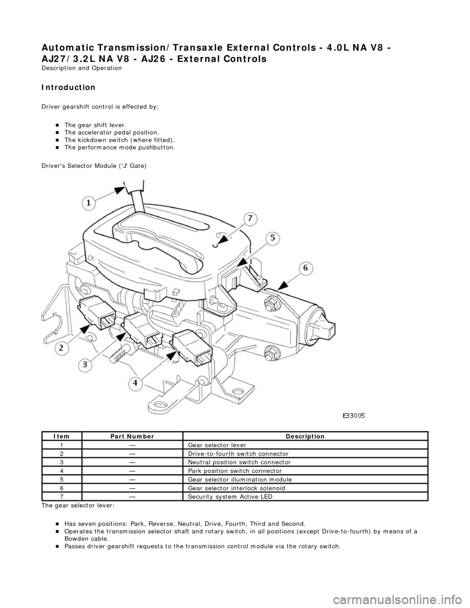
Driver's Selector Module ('J' Gate)
The gear selector lever:
Has seven positions: Park, Reverse, Neutral, Drive, Fourth, Third and Second. Operates the transmission selector shaft and rotary switch, in all positions (except Drive-to-fourth) by means of a
Bowden cable.
Passes driver gearshift requests to the transm ission control module via the rotary switch.
ItemPart NumberDescription
1—Gear selector lever
2—Drive-to-fourth switch connector
3—Neutral position switch connector
4—Park position switch connector
5—Gear selector illumination module
6—Gear selector interlock solenoid
7—Security system Active LED
Page 1743 of 2490
Accelerati
on Control - Accelerator Cable Adjustment
Gen
eral Procedures
1.
Load the Approved Jaguar Diagno stic System with power train
data logger.
2. Connect the Approved Jaguar Diag nostic System to the vehicle.
3. W
ith 'Disable Network Integrity Test - YES/ NO' displayed on
the screen select YES.
4. With new menu displayed on the screen, select ' Engine
Management'.
5. Turn the ignition to ON.
R
emove any previously selected data logger parameters.
6. On data logger select PPS11 an d PPS2 (Pedal demand sensors
1 and 2).
7. On Sedan models only, remove the bulkhead covers on both
sides and the engine compartment rear cover.
8. Cut, remove and discard the ra tchet strap which retains the
throttle cable to the abutment bracket.
9. Ensure there is no tension on the throttle cable by releasing
the throttle cable adjustment nut from the abutment bracket.
10. Record the voltages for both sensors, PPS11 and PPS2.
11. Partially insert the throttle cable adjustment nut into the
abutment bracket.
12. Recheck the voltages for both sensors, PPS11 and PPS2.
13. Where the voltages at step 12 are higher than the voltages
taken at step 10, contin ue to step 15 below.
14. Where the voltages at step 12 are the same as the voltages
taken at step 10, contin ue to step 16 below.
15. Rotate the adjustment nut clockwise (as viewed from the
front of the vehicle) until the same voltages are indicated as in
step 10. Continue to turn thro ugh a part revolution until the
sides of the nut are vertical. Tu rn through a further 90 degrees,
then fully insert the nut into the abutment bracket.
16. Rotate the adjustment nut anti-clockwise (as viewed from the
front of the vehicle) until the indicated voltage starts to
increase. Then rotate the nut clockwise through a part
revolution until the sides are ve rtical. Turn through a further 90
degrees, then fully insert the nut into the abutment bracket.
17. Fit a new ratchet strap to secure the throttle cable adjusting
nut to the abutment bracket.
18. Operate the throttle pedal through 20 full cycles to settle the
cable. Check the voltages now shown, remain the same as in
steps 15 and 16.
19. Check and where necessary adjust the kickdown switch. For
additional information, refer to Section 307
-05A Automatic Transmissi
on/Transaxle External Controls
Sectio
n
307
-05
B
Au
tomatic Transmission/Tra
nsaxle External Controls
.
20
.
On Sedan models only, refit the engine compartment rear
cover and the bulkhead co vers on both sides.
21. Switch the ignition OFF and disconnect the Approved Jaguar
Diagnostic System.
Page 1756 of 2490
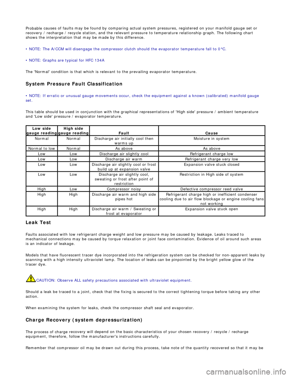
Probable
causes of faults may be found by comparing actual
system pressures, registered on your manifold gauge set or
recovery / recharge / recycle station, and the relevant pressure to temperature relationship graph. The following chart
shows the interpretation that ma y be made by this difference.
• NOTE: The A/CCM will disengage the compressor clutch should the evaporator temperature fall to 0°C.
• NOTE: Graphs are typical for HFC 134A
The 'Normal' condition is that which is relevant to the prevailing evaporator temperature.
System Pressure Fault Classification
• NOTE
: If erratic or unusual gauge move
ments occur, check the equipment against a known (calibrated) manifold gauge
set.
This table should be used in conjunction with the graphical representations of 'High side' pressure / ambient temperature
and 'Low side' pressure / evaporator temperature.
Leak
Test
F
a
ults associated with low re
frigerant charge weight and low pressure ma y be caused by leakage. Leaks traced to
mechanical connections may be caused by to rque relaxation or joint face contamination. Evidence of oil around such areas
is an indicator of leakage.
Models that have fluorescent tracer dye incorporated into the refrigeration system can be checke d for non-apparent leaks by
scanning with a high intensity ultraviolet lamp. The location of leaks can be pinpointed by the bright yellow glow of the
tracer dye.
CAUTION: Observe ALL safety precautions associated with ultraviolet equipment.
Should a leak be traced to a joint, check that the fixing is secured to the correct tightening torque before taking any other
action.
When examining the system for leaks, chec k the compressor shaft seal and evaporator.
Charge Re
covery (system depressurization)
The process of
charge r
ecovery will depe
nd on the basic characteristics of your chosen recovery / recycle / recharge
equipment, therefore, follow the manu facturer's instructions carefully.
Remember that compressor oil may be drawn out during this process, take note of the quantity recovered so that it may be
Lo
w side
gauge reading
High s i
de
gauge reading
Fau l
t
Cause
No
r
mal
No
r
mal
Di
sc
harge air initially cool then
warms up
Mois
ture in system
N
ormal
to low
No
r
mal
As aboveAs above
LowLowD
i
scharge air slightly cool
Ref
r
igerant charge low
LowLowDi
scharge air warm
Refr
igerant charge very low
LowLowDi
scharge air slightly cool or frost
build up at expansion valve
Expansion valve st
uck closed
LowLowDi
scharge air slightly cool,
sweating or frost after point of restriction
Restri
ction in High side of system
HighLowCompressor noisyDe
fe
ctive compressor reed valve
HighHighD
i
scharge air warm and high side
pipes hot
Refri
gerant charge high or inefficient condenser
cooling due to air flow blockage or engine cooling fans
not working
HighHighD i
scharge air warm / Sweating or
frost at evaporator
Expans ion valve st
uck open
Page 1758 of 2490
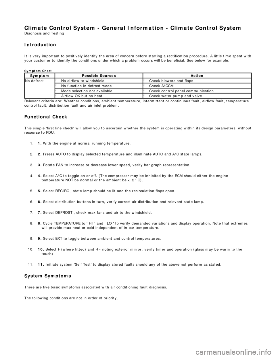
Climate Control System - General Informatio
n - Climate Control System
D
iagn
osis and Testing
I
n
troduction
It is very i
m
portant to positive
ly identify the area of concern before starting a rectification procedure. A little time spent with
your customer to identify the conditions under which a pr oblem occurs will be beneficial. See below for example:
Sym
ptom Chart
Re
lev
ant criteria are: Weather conditions,
ambient temperature, intermittent or cont inuous fault, airflow fault, temperature
control fault, distribution fault and air inlet problem.
Functio n
al Check
This
s
imple 'first line check' will allo
w you to ascertain whether the system is operating within its design parameters, withou t
recourse to PDU.
1. 1. With the engine at normal running temperature.
2. 2. Presss AUTO to display selected temperature and illuminate AUTO and A/C state lamps.
3. 3. Rotate FAN to increase or decrease lowe r speed, verify bar graph representation.
4. 4. Select A/C to toggle on or off. (T he compressor may be inhibited by the ECM should either the engine
temperature NOT be normal or the ambient be < 2° C).
5. 5. Select RECIRC , state lamp should be lit and the recirculation flaps open.
6. 6. Select distribution butt ons in turn, verify correct air distribution and relevant state lamp.
7. 7. Select DEFROST , check max fans and air to the windshield.
8. 8. Cycle TEMPERATURE to ' HI ' and ' LO ' to verify demanded variations and display operation. Note that extremes
will provide max heat or cold independent of in-car temperature.
9. 9. Select EXT to toggle between am bient and control temperatures.
10. 10. Select F (where fitted) and R - noting exterior mirror; verify timer and operation (glass may be warm to the
touch)
11. 11. Initiate system 'Self Test' to display stored faul ts should any of the above not perform as stated.
Sy
stem Symptoms
There
are five
basic symptoms associated
with air conditioning fault diagnosis.
The following conditions are not in order of priority.
Sy m
ptom
Possib
l
e Sources
Acti
o
n
N
o defrostN o
airflow to windshield
*
Check blower s and flaps
*
N o functi
on in defrost mode
*
Check A/CCM
*
Mo de s
election not available
*
Chec k
control panel communication
*
Ai rfl
ow OK but no heat
*
Check water pu
mp and valve
*