compression ratio JAGUAR X308 1998 2.G Workshop Manual
[x] Cancel search | Manufacturer: JAGUAR, Model Year: 1998, Model line: X308, Model: JAGUAR X308 1998 2.GPages: 2490, PDF Size: 69.81 MB
Page 273 of 2490
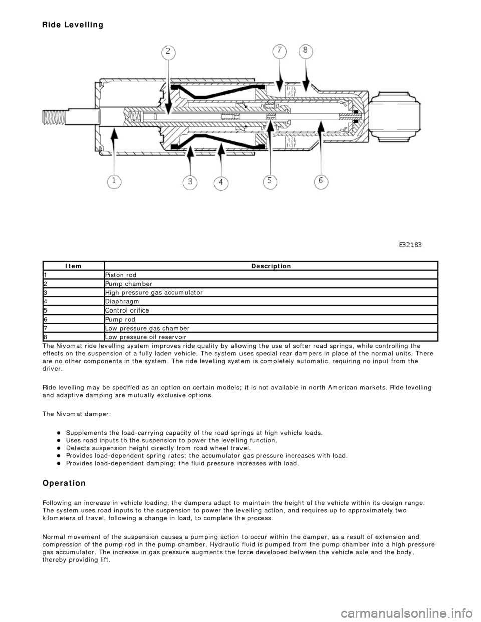
The
Nivomat ride levelling system improves ride quality by al
lowing the use of softer road springs, while controlling the
effects on the suspension of a fully laden vehicle. The system uses special rear dampers in place of the normal units. There
are no other components in th e system. The ride levelling system is comple tely automatic, requiring no input from the
driver.
Ride levelling may be specified as an opti on on certain models; it is not available in north American markets. Ride levelling
and adaptive damping are mu tually exclusive options.
The Nivomat damper:
Su
pplements the load-carrying capacity of th
e road springs at high vehicle loads.
Uses road inputs to the
suspension to power the levelling function.
De
tects suspension height dire
ctly from road wheel travel.
Provi
des load-dependent spring rates; the ac
cumulator gas pressure increases with load.
Pr
ovides load-dependent damping; the fluid pressure increases with load.
Op
eration
F
ollowing an increase in vehicle loading,
the dampers adapt to maintain the height of the vehicle within its design range.
The system uses road inputs to the suspension to power the levelling action, and requires up to approximately two
kilometers of travel, following a change in load, to complete the process.
Normal movement of the suspension caus es a pumping action to occur within the damper, as a result of extension and
compression of the pump rod in the pump chamber. Hydraulic fluid is pumped from the pump cham ber into a high pressure
gas accumulator. The increase in gas pressure augments the force developed between th e vehicle axle and the body,
thereby providing lift.
It
em
De
scription
1Pi
ston rod
2Pum
p chamber
3High
pressure
gas accumulator
4Diaphragm
5Co
ntrol orifice
6Pump rod
7Low pressure gas ch
amber
8Low pressure oil
reservoir
Ride Levelling
Page 521 of 2490
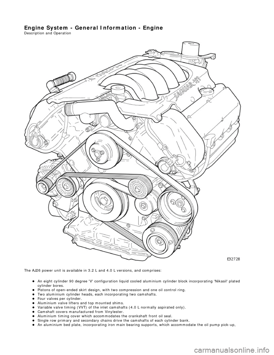
Engine System - General Infor
mation - Engine
Description an
d Operation
The AJ26 power unit is available in 3.2 L and 4.0 L versions, and comprises:
An eight cylinder 9
0 degree 'V' config
uration liquid cooled aluminium cylinder block incorporating 'Nikasil' plated
cylinder bores.
Pi
stons of open-ended skirt design, with
two compression and one oil control ring.
Two al
uminium cylinder heads, each
incorporating two camshafts.
F
our valves per cylinder.
Al
uminium valve lifters and top mounted shims.
Vari
able valve timing (VVT) of the inlet camshafts (4.0 L normally aspirated only).
Camshaft
covers manufactured from Vinylester.
Al
uminium timing cover which accommodat
es the crankshaft front oil seal.
Sin
gle row primary and secondary chains dr
ive the camshafts of each cylinder bank.
An alu
minium bed pl
ate, incorporating iron main bearing supports, which accomm odate the oil pump pick-up,
Page 528 of 2490
Speed an
d load
Coo
l
ant temperature
Ti
me el
apsed from start up
Cl
osed l
oop fuelling
Determination of the vapour concentration is made by stepped opening of the EVAP valve and subsequent monitoring of the
fuelling correction. This function is performed prior to purging, so that at the onse t of purging the EVAP valve can be set to
the optimum position. Should the ECM be unable to determine the concentration before purging, a default value is
employed, which is then modified whilst purging is in progress.
When the purging process is operational th e ECM modifies the basic fuelling calculation to maintain the correct air / fuel
ratio.
Purging is inhibited during fuel cut-off and stability / traction control intervention.
Coolant Temperature Sen
sor
Th
e
sensor outputs a voltage to the ECM which decreases as temperature increases.
Cooling Fans
In response to engi
ne coolant temperat
u
re and climate control system demand, the ECM will energize the cooling fans.
Climate Control Compressor
The E
C
M will allow the compressor clutch to be engaged if th
e engine temperature and load demand are normal. Should the
driver require maximum engine powe r or the coolant temperature be high, the request will be denied.
Cranking Signal
The ECM reacts to a signal fr
om th
e Body Processor Module (BPM) when the starter motor relay is energi
zed. This signal is
used to trigger starting, fu el and ignition strategies.
Engine Speed and Cranksh
aft Position
Engine
speed and cran
k position are moni
tored by a sensor which is mounted on the cylinder block (flywheel housing)
behind the crankshaft drive plat e. It indicates rotational speed to the ECM in the form of 12 pulses per crank revolution.
Engine speed is used for synchronization of fuel an d ignition systems, as well as other functions.
Camshaft Position
The ca
mshaft position sensor is mounted at
the rear of Bank 2 cylinder head on the inlet side and provides one signal every
720 degrees of crankshaft rotation. The signal, in conjunction with the signal from the crankshaft position sensor, indicates
to the ECM that the piston of cylinder 1A is approaching TDC on the compression stroke.
Variable Valve
Timing (Where Fitted)
By energi
si
ng a solenoid to allow the pass
age of pressurized oil on each of the inle t camshaft drives, the ECM can vary by a
single stepped amount, the relati ve timing of the inlet valves.
Ign
ition
Ignit
i
on spark is produced by
individual on-plug coil units.
There are two ignition amplifiers; module #1 drives coils 1A, 2B, 3B and 4A, whilst module #2 drives coils 1B, 2A, 3A and
4B. The ECM controls the amplifiers.
Page 1021 of 2490
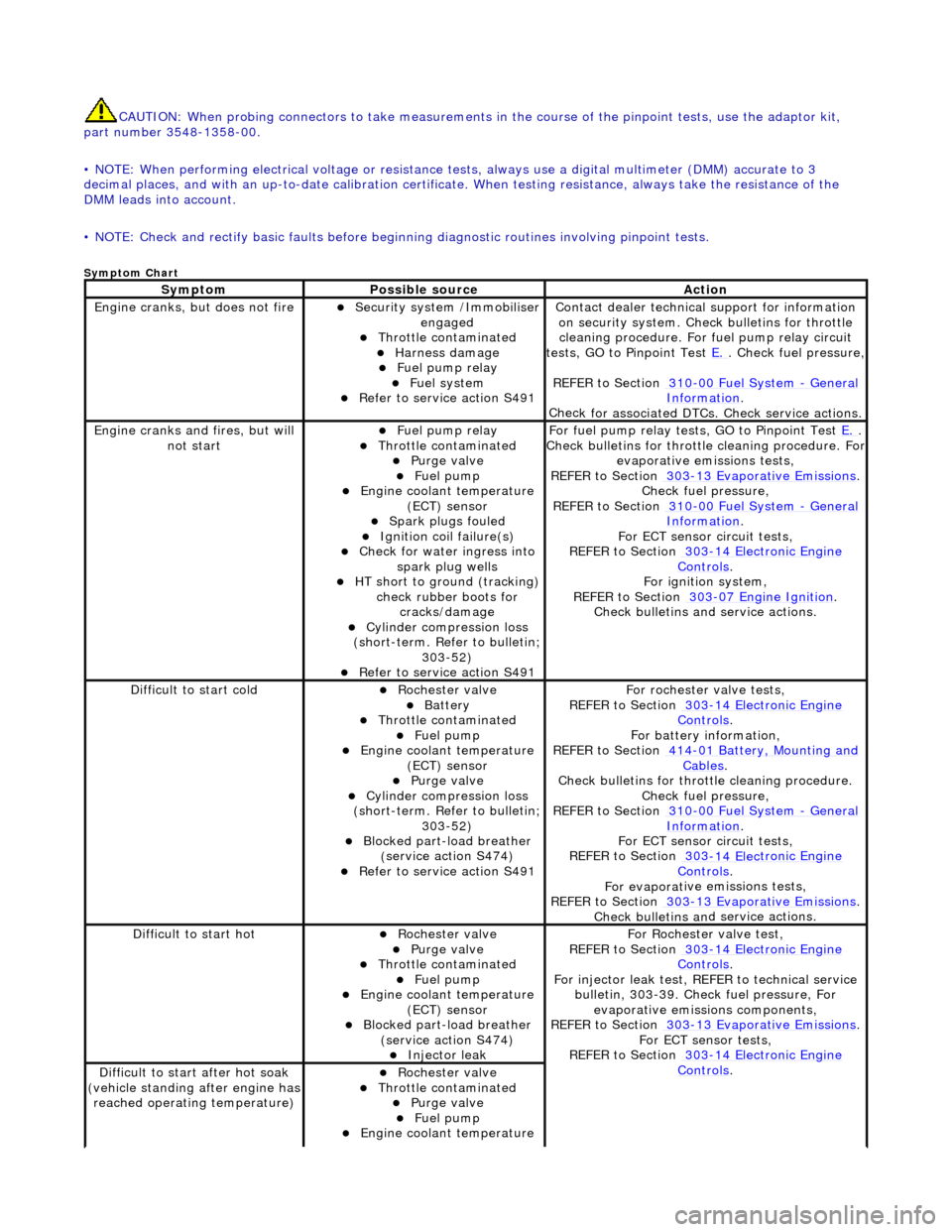
CAUTI
ON: When probing connectors to take
measurements in the course of the pinpoint tests, use the adaptor kit,
part number 3548-1358-00.
• NOTE: When performing electrical voltag e or resistance tests, always use a digital multimeter (DMM) accurate to 3
decimal places, and with an up-t o-date calibration certificate. When testing resistance, always take the resistance of the
DMM leads into account.
• NOTE: Check and rectify basic faults before beginning diagnostic ro utines involving pinpoint tests.
Sy
mptom Chart
Sy
mptom
Possib
le source
Acti
on
Engine
cranks, but does not fire
Secu
rity system /Immobiliser
engaged
Thr
ottle contaminated
Harness damage
F
uel pump relay
Fue
l system
R
efer to service action S491
Contact dealer techn
ical
support for information
on security system. Chec k bulletins for throttle
cleaning procedure. For fuel pump relay circuit
tests, GO to Pinpoint Test E.
.
Check fuel pressure,
REFER to Section 310
-00
Fuel System
- Gen
eral
Informati
on
.
Chec
k for associated DTCs
. Check service actions.
Engine
cranks and fires, but will
not start
F
uel pump relay
Thr
ottle contaminated
Purge
valve
Fue
l pump
Engine coolan
t temperature
(ECT) sensor
Spark plugs
fouled
Ignition coil
failure(s)
Check f
or water ingress into
spark plug wells
HT sho
rt to ground (tracking)
check rubber boots for cracks/damage
Cyl
inder compression loss
(short-term. Refer to bulletin;
303-52)
R
efer to service action S491
F
or fuel pump relay tests,
GO to Pinpoint Test E.
.
Check bull
etins for throttle cleaning procedure. For
evaporative emissions tests,
REFER to Section 303
-1
3 Evaporative Emissions
. Chec
k fuel pressure,
REFER to Section 310
-00
Fuel System
- Ge
neral
Informati
on
.
F
or ECT sensor circuit tests,
REFER to Section 303
-14 Elec
tronic Engine
Controls.
For ign
ition system,
REFER to Section 303
-07
Engine Ignition
.
Check bulletins an d service
actions.
D
ifficult to start cold
Roc
hester valve
Batt
ery
Thr
ottle contaminated
Fue
l pump
Engine coolan
t temperature
(ECT) sensor
Purge
valve
Cyl
inder compression loss
(short-term. Refer to bulletin;
303-52)
Blocked part-load breather (
service action S474)
R
efer to service action S491
F
or rochester valve tests,
REFER to Section 303
-14 Elec
tronic Engine
Controls.
F
or battery information,
REFER to Section 414
-0
1 Battery, Mounting and
Cables.
Check bull
etins for throttle cleaning procedure.
Check fuel pressure,
REFER to Section 310
-00
Fuel System
- Ge
neral
Informati
on
.
F
or ECT sensor circuit tests,
REFER to Section 303
-14 Elec
tronic Engine
Controls.
For evaporat
ive emissions tests,
REFER to Section 303
-1
3 Evaporative Emissions
. Check bulletins an
d
service actions.
D
ifficult to start hot
Roc
hester valve
Purge
valve
Thr
ottle contaminated
Fue
l pump
Engine coolan
t temperature
(ECT) sensor
Blocked part-load breather (
service action S474)
Injec
tor leak
F
or Rochester
valve test,
REFER to Section 303
-14 Elec
tronic Engine
Controls.
Fo
r injector leak test, REFER to technical service
bulletin, 303-39. Check fuel pressure, For evaporative emissions components,
REFER to Section 303
-1
3 Evaporative Emissions
. F
or ECT sensor tests,
REFER to Section 303
-14 Elec
tronic Engine
Controls. D
ifficult to start after hot soak
(vehicle standing after engine has
reached operating temperature)
Roc
hester valve
Thr
ottle contaminated
Purge
valve
Fue
l pump
Engine coolan
t temperature
Page 1066 of 2490
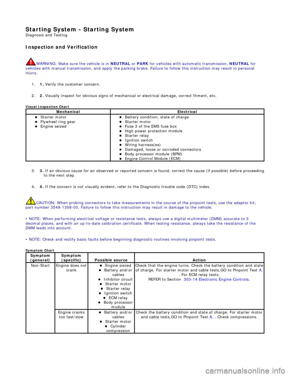
Starting System - Starting System
Diagn
osis and Testing
I
n
spection and Verification
W
A
RNING: Make sure
the vehicle is in NEUTRAL or PARK for vehicles with au tomatic transmission, NEUTRAL for
vehicles with manual transmissi on, and apply the parking brake. Failure to foll ow this instruction may result in personal
injury.
1. 1. Verify the customer concern.
2. 2. Visually inspect for obvious signs of mechanical or electrical damage, correct fitment, etc.
Vi
sual Inspection Chart
3.
3. If an obvi
ous cause for an observed or
reported concern is found, correct th e cause (if possible) before proceeding
to the next step.
4. 4. If the concern is not visually evident, refer to the Diagnostic trouble code (DTC) index.
CAUTION: When probing connectors to take measurements in the course of the pinpoint tests, use the adaptor kit,
part number 3548-1358-00. Failure to follow this in struction may result in damage to the vehicle.
• NOTE: When performing electrical voltag e or resistance tests, always use a digital multimeter (DMM) accurate to 3
decimal places, and with an up-t o-date calibration certificate. When testing resistance, always take the resistance of the
DMM leads into account.
• NOTE: Check and rectify basic faults before beginning diagnostic ro utines involving pinpoint tests.
Sym
ptom Chart
MechanicalElectrical
Starte
r motor
Flywheel
ring gear
Engine
s
eized
Batter
y condition, state of charge
Starte
r motor
F
u
se 3 of the EMS fuse box
High
power protec ti
on module
Starter relay Ignition switc
h
W
i
ring harness(es)
Damaged, loose or corroded connector
s
Body processor module (B
PM)
Engine
C
ontrol Module (ECM)
Sy
m
ptom
(
gene r
al)
Sy
m
ptom
(specific)
Possib l
e source
Acti
o
n
No
n
-Start
Engine does
not
crankEngine s
iezed
Batt
ery and
/or
cables
Inhibitor circuit St arte
r motor
Starter relay Ignition switc
h
ECM relay Body processor
modu le
Check that
the engine turns. Check the battery condition and state
of charge. For starter motor and ca ble tests,GO to Pinpoint Test A.
. For ECM relay
tests,
REFER to Section 303
-14
Electronic Engine Controls
.
Engine
c
ranks
too fast/slow
Batt ery and
/or
cables
St arte
r motor
Cy
linder
com
pression
Check the battery con
dition
and st
ate of charge. For starter motor
and cable tests,GO to Pinpoint Test A.
. Chec
k compressions.
Page 1078 of 2490
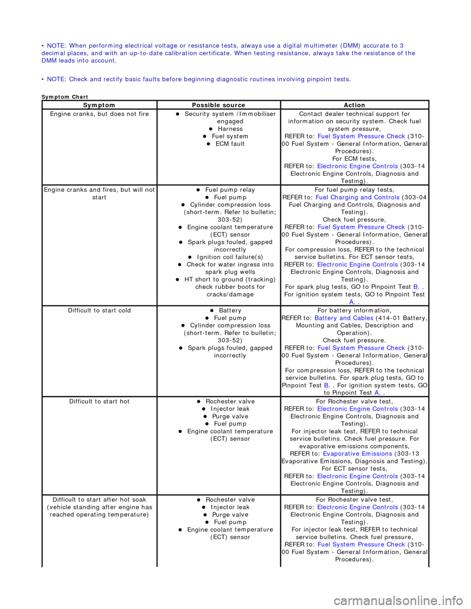
• NO
TE: When performing electrical voltag
e or resistance tests, always use a digital multimeter (DMM) accurate to 3
decimal places, and with an up-t o-date calibration certificate. When testing resistance, always take the resistance of the
DMM leads into account.
• NOTE: Check and rectify basic faults before beginning diagnostic ro utines involving pinpoint tests.
Sym
ptom Chart
Sy
m
ptom
Possib
l
e source
Acti
o
n
Engine
cranks, but does
not fire
Secu
rit
y system /Immobiliser
engaged
Harness Fue l
system
ECM fault
Contact deal er techni
cal support for
information on security system. Check fuel
system pressure,
REFER to: Fuel System Pressure Check
(310
-
00 Fuel System - Genera l Information, General
Procedures).
For ECM tests,
REFER to: Electronic Engine Controls
(303
-14
Electronic Engine Co ntrols, Diagnosis and
Testing).
Engine cranks and
fi
res, but will not
start
Fu
el pump relay
Fuel
pump
Cyl
i
nder compression loss
(short-term. Refer to bulletin; 303-52)
Engine coolan t
temperature
(ECT) sensor
Spark plugs fouled, gapp
ed
incorrectly
Ignition coil fail
ure(s)
Check f
o
r water ingress into
spark plug wells
HT sho rt to ground (tracking)
check rubber
boots for
cracks/damage
Fo
r fuel pump relay tests,
REFER to: Fuel Charging and Controls
(303
-04
Fuel Charging and Controls, Diagnosis and Testing).
Check fuel pressure,
REFER to: Fuel System Pressure Check
(310
-
00 Fuel System - Genera l Information, General
Procedures).
For compression loss, REFER to the technical service bulletins. For ECT sensor tests,
REFER to: Electronic Engine Controls
(303
-14
Electronic Engine Co ntrols, Diagnosis and
Testing).
For spark plug tests, GO to Pinpoint Test B.
.
For ign i
tion system tests, GO to Pinpoint Test
A.
.
Diff
icult to start cold
Batt
ery Fuel
pump
Cyl
i
nder compression loss
(short-term. Refer to bulletin; 303-52)
Spark plugs fouled, gapp
ed
incorrectly
F o
r battery information,
REFER to: Battery and Cables
(414
-01 Battery,
Mounting and Cables, Description and Operation).
Check fuel pressure.
REFER to: Fuel System Pressure Check
(310
-
00 Fuel System - Genera l Information, General
Procedures).
For compression loss, REFER to the technical service bulletins. For spark plug tests, GO to
Pinpoint Test B.
. For ig
nition system tests, GO
to Pinpoint Test A.
.
Diff
icult to start hot
Roc
h
ester valve
Injec
t
or leak
Purge
val
ve
Fue
l
pump
Engine coolan
t
temperature
(ECT) sensor
F or R
ochester
valve test,
REFER to: Electronic Engine Controls
(303
-14
Electronic Engine Co ntrols, Diagnosis and
Testing).
For injector leak test, REFER to technical
service bulletins. Check fuel pressure. For evaporative emissions components,
REFER to: Evaporative Emissions
(303
-13
Evaporative Emissions, Diagnosis and Testing).
For ECT sensor tests,
REFER to: Electronic Engine Controls
(303
-14
Electronic Engine Co ntrols, Diagnosis and
Testing).
D iff
icult to start after hot soak
(vehicle standing after engine has reached operating temperature)
Roc h
ester valve
Injec
t
or leak
Purge
val
ve
Fue
l
pump
Engine coolan
t
temperature
(ECT) sensor
F or R
ochester
valve test,
REFER to: Electronic Engine Controls
(303
-14
Electronic Engine Co ntrols, Diagnosis and
Testing).
For injector leak test, REFER to technical service bulletins. Check fuel pressure,
REFER to: Fuel System Pressure Check
(310
-
00 Fuel System - Genera l Information, General
Procedures).
Page 1083 of 2490
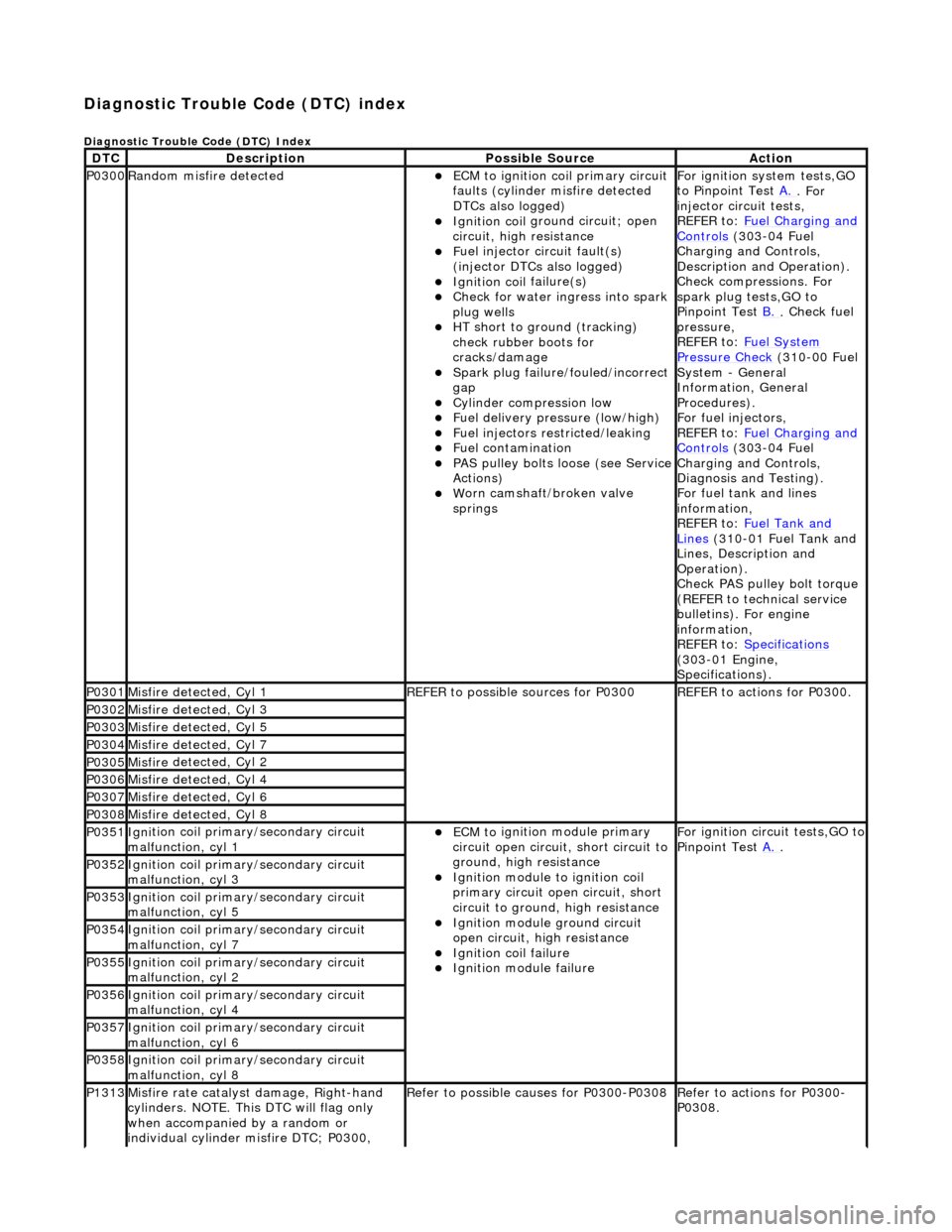
Diagnostic Trouble Code (D
TC) index
D
iagnostic Trouble Code (DTC) Index
DT
C
De
scription
Possib
le Source
Acti
on
P0300Ran
dom misfire detected
ECM t
o ignition coil primary circuit
faults (cylinder misfire detected
DTCs also logged)
Ignition coil
ground circuit; open
circuit, high resistance
F
uel injector circuit fault(s)
(injector DTCs also logged)
Ignition coil
failure(s)
Check f
or water ingress into spark
plug wells
HT sho
rt to ground (tracking)
check rubber boots for
cracks/damage
Spark plug
failure/fouled/incorrect
gap
Cy
linder compression low
F
uel delivery pressure (low/high)
F
uel injectors restricted/leaking
Fuel contamination
P
AS pulley bolts loose (see Service
Actions)
W
orn camshaft/broken valve
springs
For ign
ition system tests,GO
to Pinpoint Test A.
. For
inje
ctor circuit tests,
REFER to: Fuel Charging and
Controls (30
3-04 Fuel
Charging and Controls,
Description and Operation).
Check compressions. For
spark plug tests,GO to
Pinpoint Test B.
.
Check fuel
pressure,
REFER to: Fuel System
Pressure Check (31
0-00 Fuel
System - General
Information, General
Procedures).
For fuel injectors,
REFER to: Fuel Charging and
Controls (30
3-04 Fuel
Charging and Controls,
Diagnosis and Testing).
For fuel tank and lines
information,
REFER to: Fuel Tank and
Lin
es
(310-01 Fuel Tank and
Lines, Description and
Operation).
Check PAS pulley bolt torque
(REFER to technical service
bulletins). For engine
information,
REFER to: Specifications
(3
03-01 Engine,
Specifications).
P0301Misfire
detected, Cyl 1
R
EFER to possible sources for P0300
R
EFER to actions for P0300.
P0302Misfire
detected, Cyl 3
P0303Misfire
detected, Cyl 5
P0304Misfire
detected, Cyl 7
P0305Misfire
detected, Cyl 2
P0306Misfire
detected, Cyl 4
P0307Misfire
detected, Cyl 6
P0308Misfire
detected, Cyl 8
P0351Igni
tion coil primary/secondary circuit
malfunction, cyl 1
ECM to
ignition module primary
circuit open circuit, short circuit to
ground, high resistance
Igni
tion module to ignition coil
primary circuit open circuit, short
circuit to ground, high resistance
Ignition modu
le ground circuit
open circuit, hi gh resistance
Ignition coil
failure
Ignition modul
e failure
F
or ignition circuit tests,GO to
Pinpoint Test A.
.
P0352Igni
tion coil primary/secondary circuit
malfunction, cyl 3
P0353Igni
tion coil primary/secondary circuit
malfunction, cyl 5
P0354Igni
tion coil primary/secondary circuit
malfunction, cyl 7
P0355Igni
tion coil primary/secondary circuit
malfunction, cyl 2
P0356Igni
tion coil primary/secondary circuit
malfunction, cyl 4
P0357Igni
tion coil primary/secondary circuit
malfunction, cyl 6
P0358Igni
tion coil primary/secondary circuit
malfunction, cyl 8
P1313Misfire rate
catalyst damage, Right-hand
cylinders. NOTE. This DTC will flag only
when accompanied by a random or
individual cylinder misfire DTC; P0300,
R
efer to possible causes for P0300-P0308
R
efer to actions for P0300-
P0308.
Page 1190 of 2490
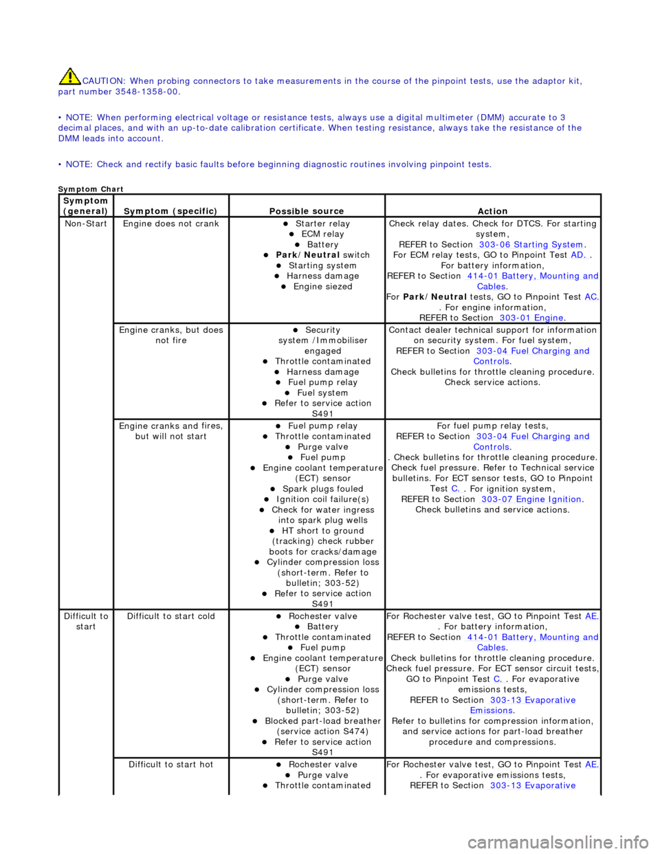
CAUTIO
N: When probing connectors to take
measurements in the course of the pinpoint tests, use the adaptor kit,
part number 3548-1358-00.
• NOTE: When performing electrical voltag e or resistance tests, always use a digital multimeter (DMM) accurate to 3
decimal places, and with an up-t o-date calibration certificate. When testing resistance, always take the resistance of the
DMM leads into account.
• NOTE: Check and rectify basic faults before beginning diagnostic ro utines involving pinpoint tests.
Sym
ptom Chart
Sym
ptom
(general)
S y
mptom (specific)
Possib
l
e source
Acti
o
n
No
n
-Start
Engine
does not cran
k
Starter relay ECM relay Batt
ery Park
/Neutral
switch
Starting system
Harness damage
Engine s
iezed
Check r
e
lay dates. Check
for DTCS. For starting
system,
REFER to Section 303
-06 Sta r
ting System
.
F or ECM
relay tests, GO to Pinpoint Test
AD.
.
F o
r battery information,
REFER to Section 414
-0 1
Battery, Mounting and
Cables.
Fo r
Park/Neutral tests, GO to Pinpoint Test AC.
. Fo
r engine information,
REFER to Section 303
-01 En
gine
.
Engine cranks, but does
not fireSecurity
syst
em /Immobiliser
engaged
Thr o
ttle contaminated
Harness damage
Fu
el pump relay
Fue
l
system
R
e
fer to service action
S491
Contact dealer techni
cal
support for information
on security system. For fuel system,
REFER to Section 303
-0 4
Fuel Charging and
Controls.
Check bull etins for throttl
e cleaning procedure.
Check service actions.
Engine cranks an d
fires,
but will not start
F u
el pump relay
Thr
o
ttle contaminated
Purge
val
ve
Fue
l
pump
Engine coolan
t
temperature
(ECT) sensor
Spark plugs
fouled
Ignition coil
fail
ure(s)
Check f
o
r water ingress
into spark plug wells
HT sh o
rt to ground
(tracking) check rubber
boots for cracks/damage
Cyli
nder compression loss
(short-term. Refer to bulletin; 303-52)
Re
fer to service action
S491
Fo
r fuel pump relay tests,
REFER to Section 303
-0 4
Fuel Charging and
Controls.
. Check bulletins for throttl
e cleaning procedure.
Check fuel pressure. Refe r to Technical service
bulletins. For ECT sensor tests, GO to Pinpoint Test C.
. Fo
r ignition system,
REFER to Section 303
-07 En
gine Ignition
.
Check bulletins an d service a
ctions.
Di
f
ficult to
start
D iff
icult to start cold
Roc
h
ester valve
Batt
ery Thro
ttle contaminated
Fue
l
pump
Engine coolan
t
temperature
(ECT) sensor
Purge val
ve
Cyl
i
nder compression loss
(short-term. Refer to bulletin; 303-52)
Blocked part-load breather (s
ervice action S474)
R
e
fer to service action
S491
For R
ochester valv
e test, GO to Pinpoint Test AE.
. Fo
r battery information,
REFER to Section 414
-0 1
Battery, Mounting and
Cables.
Check bull etins for throttl
e cleaning procedure.
Check fuel pressure. For ECT sensor circuit tests,
GO to Pinpoint Test C.
. F
or evaporative
emissions tests,
REFER to Section 303
-1 3
Evaporative
Emiss
i
ons
.
R e
fer to bulletins for co
mpression information,
and service actions for part-load breather procedure and compressions.
Diff
icult to start hot
Roc
h
ester valve
Purge
val
ve
Thr
o
ttle contaminated
F
or R
ochester valv
e test, GO to Pinpoint Test AE.
. F
or evaporative emissions tests,
REFER to Section 303
-1 3
Evaporative
Page 1803 of 2490
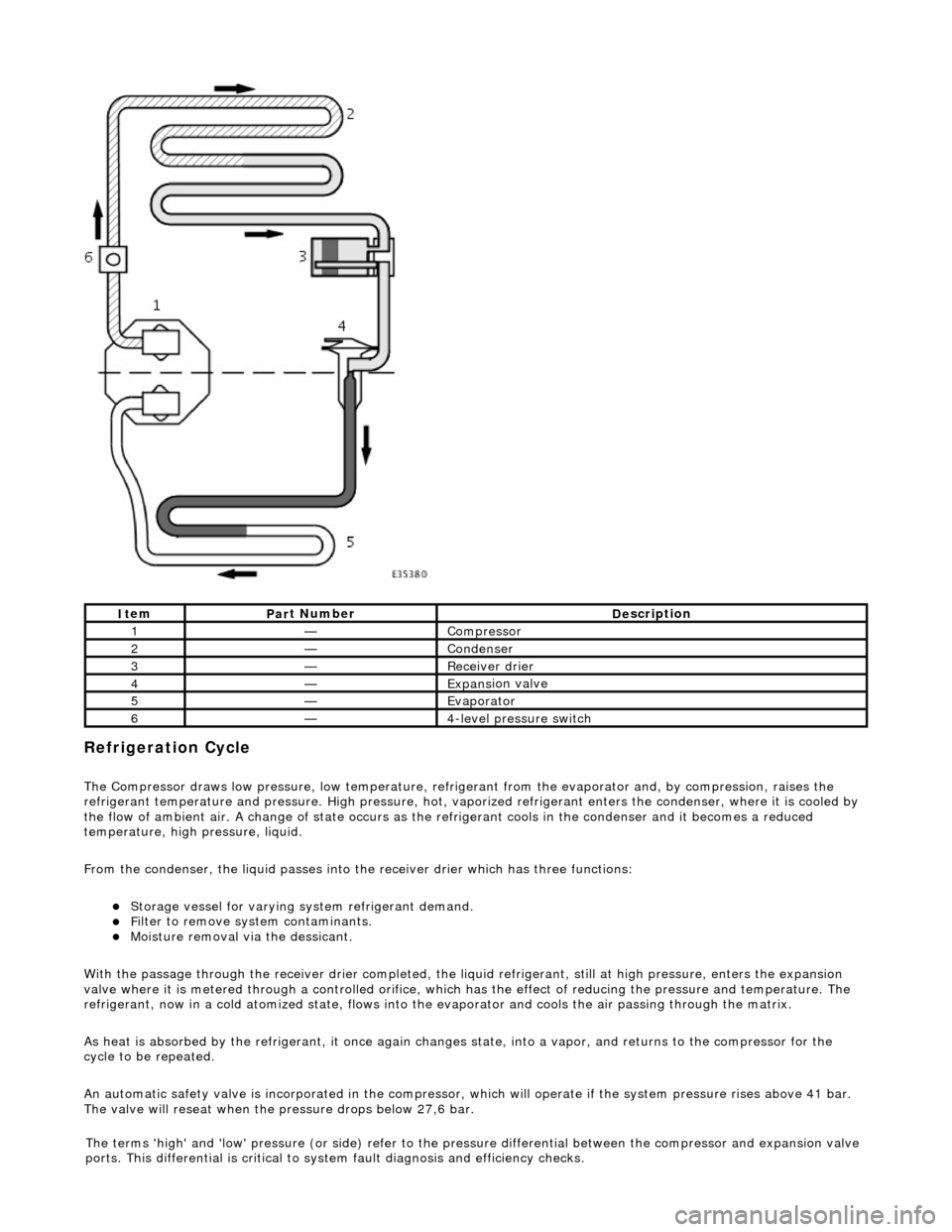
Refrigeration Cycle
The Compressor draws low pressure, lo
w te
mperature, refrigerant from the evaporat or and, by compression, raises the
refrigerant temperature and pressure. High pressure, hot, vaporized refr igerant enters the condenser, where it is cooled by
the flow of ambient air. A change of state occurs as the refrigerant cools in the condense r and it becomes a reduced
temperature, high pressure, liquid.
From the condenser, the liquid passes into the receiver drier which has three functions:
Storage vessel
for varying sy
stem refrigerant demand.
F
ilter to remove sy
stem contaminants.
Mo
isture removal via the dessicant.
With the passage through the receiver drie r completed, the liquid refrigerant, still at high pressure, enters the expansion
valve where it is metered through a contro lled orifice, which has the effect of reducing the pres sure and temperature. The
refrigerant, now in a cold atomized st ate, flows into the evaporator and cools the air passing through the matrix.
As heat is absorbed by the refrigerant, it once again changes state, into a vapor, and returns to the compressor for the
cycle to be repeated.
An automatic safety valve is incorporated in the compressor, which will operate if the system pressure rises above 41 bar.
The valve will reseat when the pressure drops below 27,6 bar.
It
em
Par
t Number
De
scription
1—Compre
ssor
2—Conden
ser
3—Re
ceiver drier
4—Expans
ion valve
5—Evaporator
6—4
-level pressure switch
The terms 'high' and 'low'
pressure (or si
de) refer to the pres sure differential betw een the compressor and expansion valve
ports. This differential is critical to sy stem fault diagnosis and efficiency checks.