Front absorber JAGUAR X308 1998 2.G User Guide
[x] Cancel search | Manufacturer: JAGUAR, Model Year: 1998, Model line: X308, Model: JAGUAR X308 1998 2.GPages: 2490, PDF Size: 69.81 MB
Page 167 of 2490
Rear
Suspension - Rear Suspension
Description an
d Operation
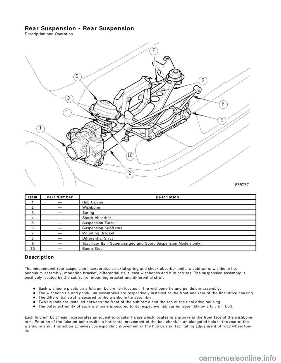
Description
The i
ndependent rear suspension incorporates co-axial sp
ring and shock absorber units, a subframe, wishbone tie,
pendulum assembly, mounting brac ket, differential strut, cast wishbones and hub carriers. The suspension assembly is
positively located by the subframe, mounting bracket and differential strut.
Each wi
shbone pivots on a fulcru
m bolt which locates in the wishbone tie and pendulum assembly.
The wish
bone tie and pendulum assemblies are respectively in
stalled at the front and rear of the final drive housing.
The differential
strut is secured to the wishbone tie assembly.
Two ti
e rods are installed between the front of the
subframe and the top of the final drive housing.
The ou
ter extremity of each wishbone
is secured to its respective hub carrier assembly by a fulcrum bolt.
Each fulcrum bolt head incorporates an ec centric circular flange which locates in a groove in the front face of the wishbone
arm. Rotation of the fulcrum bolt results in horizontal movement of the bolt shank in an elongated hole in the rear of the
wishbone arm. This acti on achieves corresponding movement of the hub carrier, facilita ting adjustment of road wheel toe-
in.
It
em
Par
t Number
De
scription
1—Hub Carrier
2—Wi
shbone
3—Sprin
g
4—Shock Absorber
5—Suspensi
on Turret
6—Suspensi
on Subframe
7—Moun
ting Bracket
8—D
ifferential Strut
9—Stabilizer Ba
r (Supercharged and
Sport Suspension Models only)
10—Bum
p Stop
Page 271 of 2490
Vehicle Dynamic Suspension - Vehicle Dynamic Suspension
Description an
d Operation
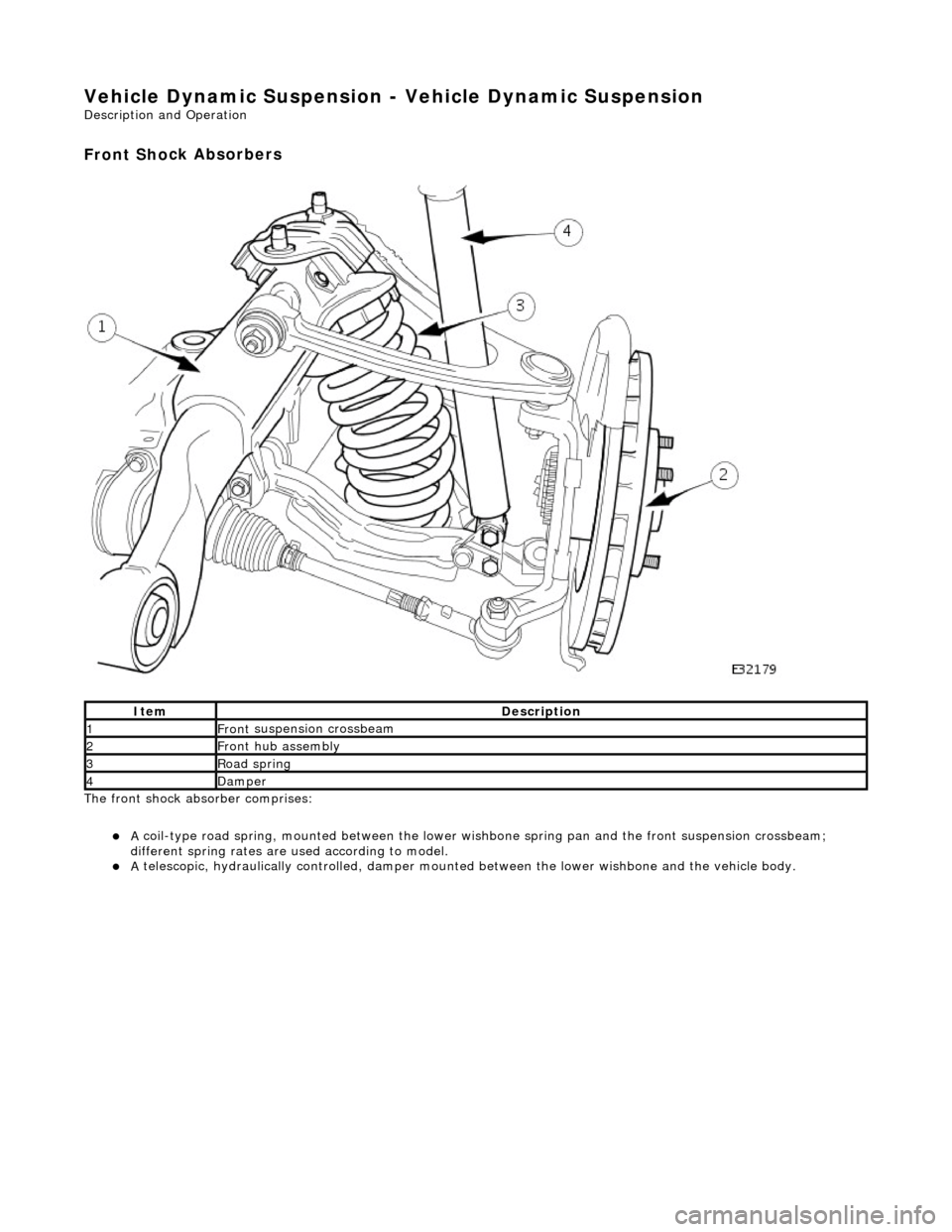
Front Sho
ck Absorbers
The front shock absorber
comprises:
A
coil-type road spring, mounted between the lower wish
bone spring pan and the front suspension crossbeam;
different spring rates are used according to model.
A
telescopic, hydraulically controlled, damper mounte
d between the lower wishbone and the vehicle body.
It
em
De
scription
1Front
suspension crossbeam
2Front
hub assembly
3Ro
ad spring
4Dam
per
Page 2426 of 2490
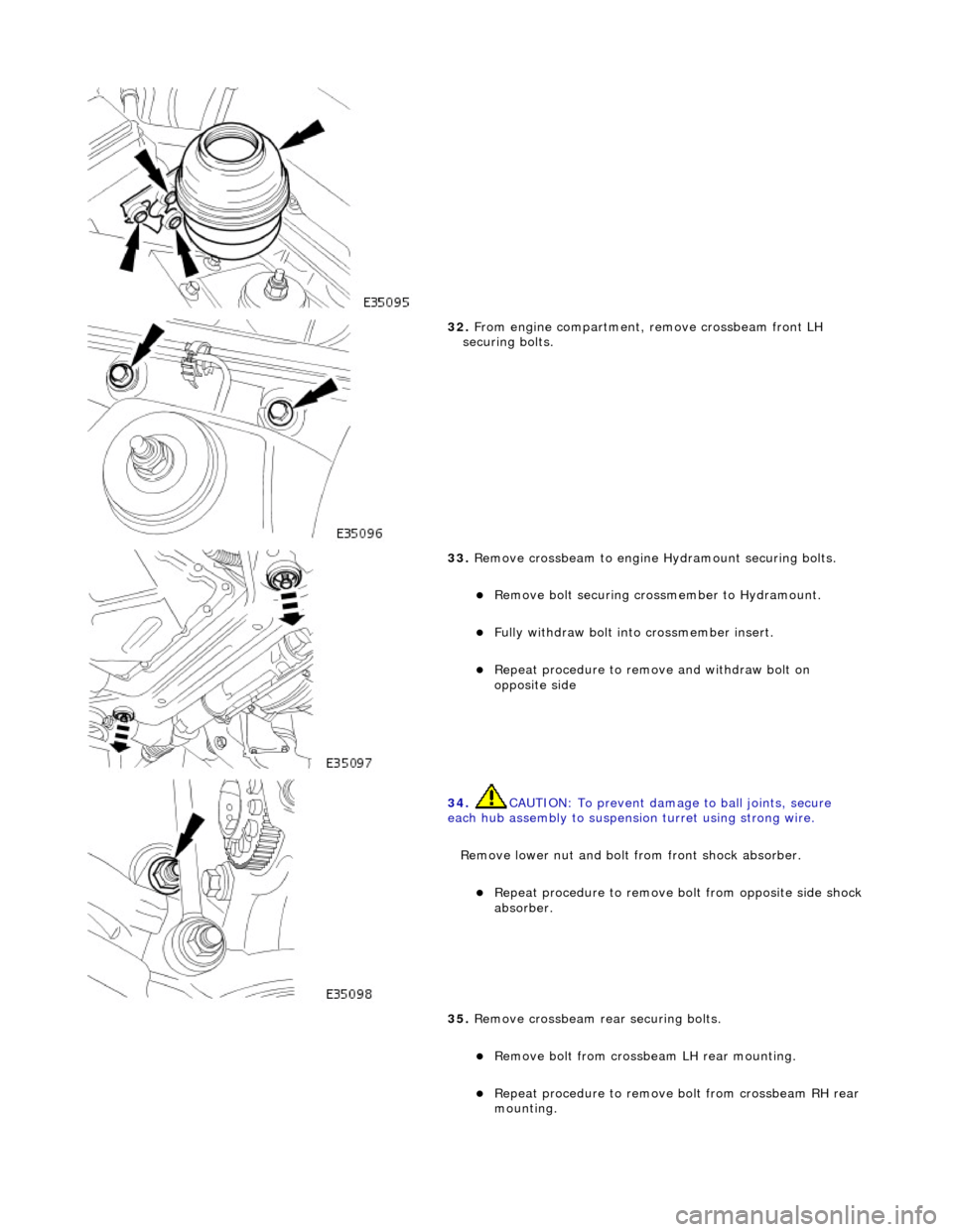
32. From engine compartment, remove crossbeam front LH
securing bolts.
33. Remove crossbeam to engine Hydramount securing bolts.
Remove bolt securing cros smember to Hydramount.
Fully withdraw bolt into crossmember insert.
Repeat procedure to remove and withdraw bolt on
opposite side
34. CAUTION: To prevent damage to ball joints, secure
each hub assembly to suspensi on turret using strong wire.
Remove lower nut and bolt from front shock absorber.
Repeat procedure to remove bo lt from opposite side shock
absorber.
35. Remove crossbeam rear securing bolts.
Remove bolt from crossbeam LH rear mounting.
Repeat procedure to remove bolt from crossbeam RH rear
mounting.
Page 2433 of 2490
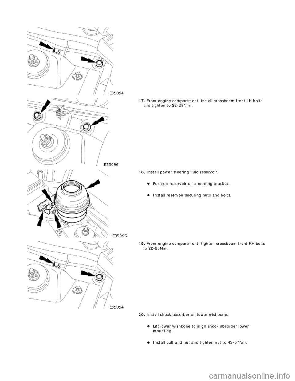
17. From engine compartment, install crossbeam front LH bolts
and tighten to 22-28Nm..
18. Install power steering fluid reservoir.
Position reservoir on mounting bracket.
Install reservoir securi ng nuts and bolts.
19. From engine compartment, tighten crossbeam front RH bolts
to 22-28Nm.
20. Install shock absorber on lower wishbone.
Lift lower wishbone to align shock absorber lower
mounting.
Install bolt and nut and ti ghten nut to 43-57Nm.
Page 2434 of 2490
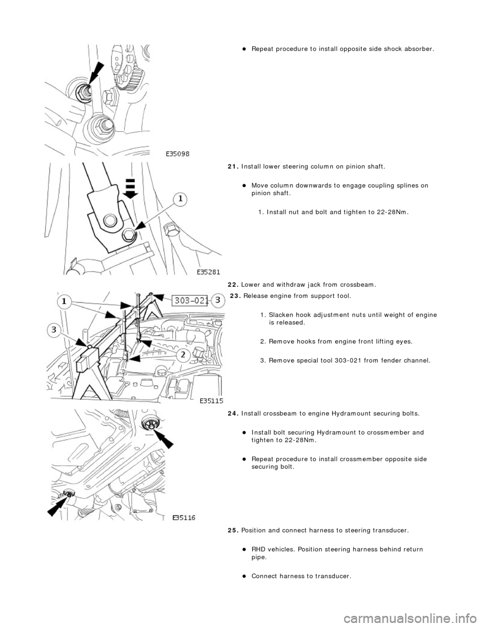
Repeat procedure to install opposite side shock absorber.
21. Install lower steering column on pinion shaft.
Move column downwards to engage coupling splines on
pinion shaft.
1. Install nut and bolt and tighten to 22-28Nm.
22. Lower and withdraw jack from crossbeam.
23. Release engine from support tool.
1. Slacken hook adjustment nuts until weight of engine is released.
2. Remove hooks from engine front lifting eyes.
3. Remove special tool 303- 021 from fender channel.
24. Install crossbeam to engine Hydramount securing bolts.
Install bolt securing Hydr amount to crossmember and
tighten to 22-28Nm.
Repeat procedure to install crossmember opposite side
securing bolt.
25. Position and connect harnes s to steering transducer.
RHD vehicles. Position steeri ng harness behind return
pipe.
Connect harness to transducer.
Page 2442 of 2490
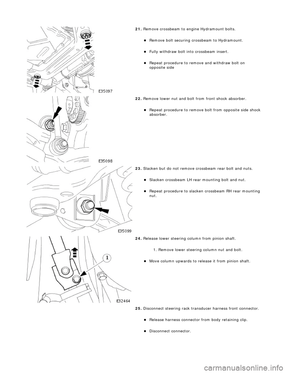
21. Remove crossbeam to engi ne Hydramount bolts.
Remove bolt securing crossbeam to Hydramount.
Fully withdraw bolt into crossbeam insert.
Repeat procedure to remove and withdraw bolt on
opposite side
22. Remove lower nut and bolt from front shock absorber.
Repeat procedure to remove bo lt from opposite side shock
absorber.
23. Slacken but do not remove crossbeam rear bolt and nuts.
Slacken crossbeam LH rear mounting bolt and nut.
Repeat procedure to slacken crossbeam RH rear mounting
nut.
24. Release lower steering column from pinion shaft.
1. Remove lower steering column nut and bolt.
Move column upwards to release it from pinion shaft.
25. Disconnect steering rack transducer harness front connector.
Release harness connector from body retaining clip.
Disconnect connector.
Page 2446 of 2490
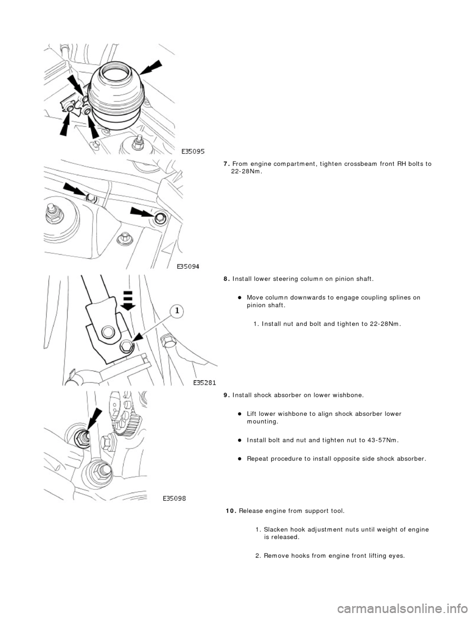
7. From engine compartment, tighten crossbeam front RH bolts to 22-28Nm.
8. Install lower steering column on pinion shaft.
Move column downwards to engage coupling splines on
pinion shaft.
1. Install nut and bolt and tighten to 22-28Nm.
9. Install shock absorber on lower wishbone.
Lift lower wishbone to align shock absorber lower
mounting.
Install bolt and nut and ti ghten nut to 43-57Nm.
Repeat procedure to install opposite side shock absorber.
10. Release engine from support tool.
1. Slacken hook adjustment nuts until weight of engine is released.
2. Remove hooks from engine front lifting eyes.
Page 2453 of 2490
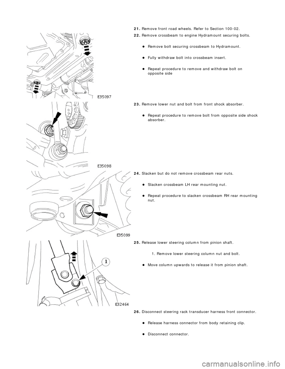
21. Remove front road wheels. Refer to Section 100-02.
22. Remove crossbeam to engine Hydramount securing bolts.
Remove bolt securing crossbeam to Hydramount.
Fully withdraw bolt into crossbeam insert.
Repeat procedure to remove and withdraw bolt on
opposite side
23. Remove lower nut and bolt from front shock absorber.
Repeat procedure to remove bo lt from opposite side shock
absorber.
24. Slacken but do not remove crossbeam rear nuts.
Slacken crossbeam LH rear mounting nut.
Repeat procedure to slacken crossbeam RH rear mounting
nut.
25. Release lower steering column from pinion shaft.
1. Remove lower steering column nut and bolt.
Move column upwards to release it from pinion shaft.
26. Disconnect steering rack transducer harness front connector.
Release harness connector from body retaining clip.
Disconnect connector.
Page 2457 of 2490
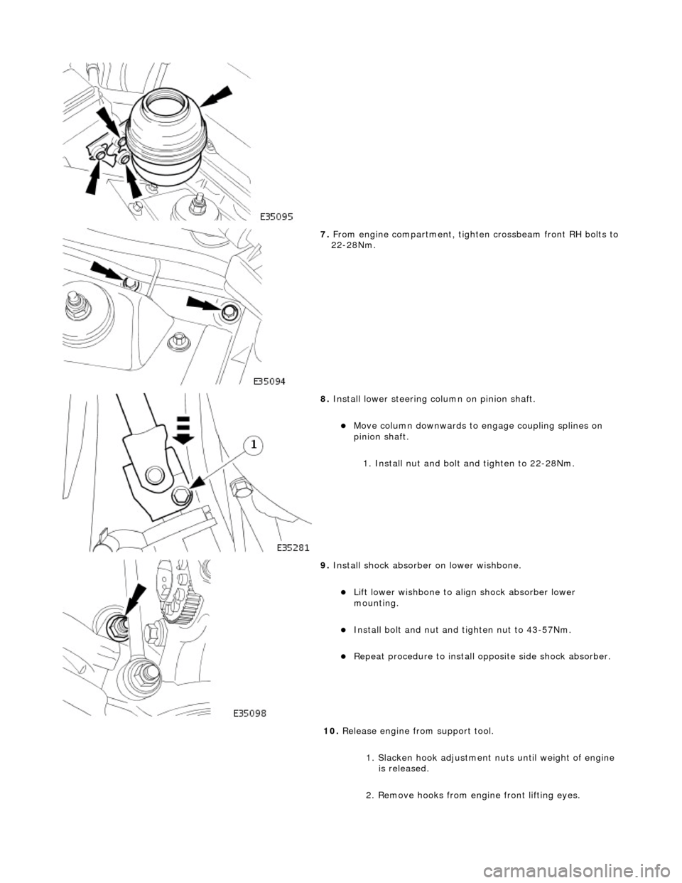
7. From engine compartment, tighten crossbeam front RH bolts to 22-28Nm.
8. Install lower steering column on pinion shaft.
Move column downwards to engage coupling splines on
pinion shaft.
1. Install nut and bolt and tighten to 22-28Nm.
9. Install shock absorber on lower wishbone.
Lift lower wishbone to align shock absorber lower
mounting.
Install bolt and nut and ti ghten nut to 43-57Nm.
Repeat procedure to install opposite side shock absorber.
10. Release engine from support tool.
1. Slacken hook adjustment nuts until weight of engine is released.
2. Remove hooks from engine front lifting eyes.
Page 2467 of 2490
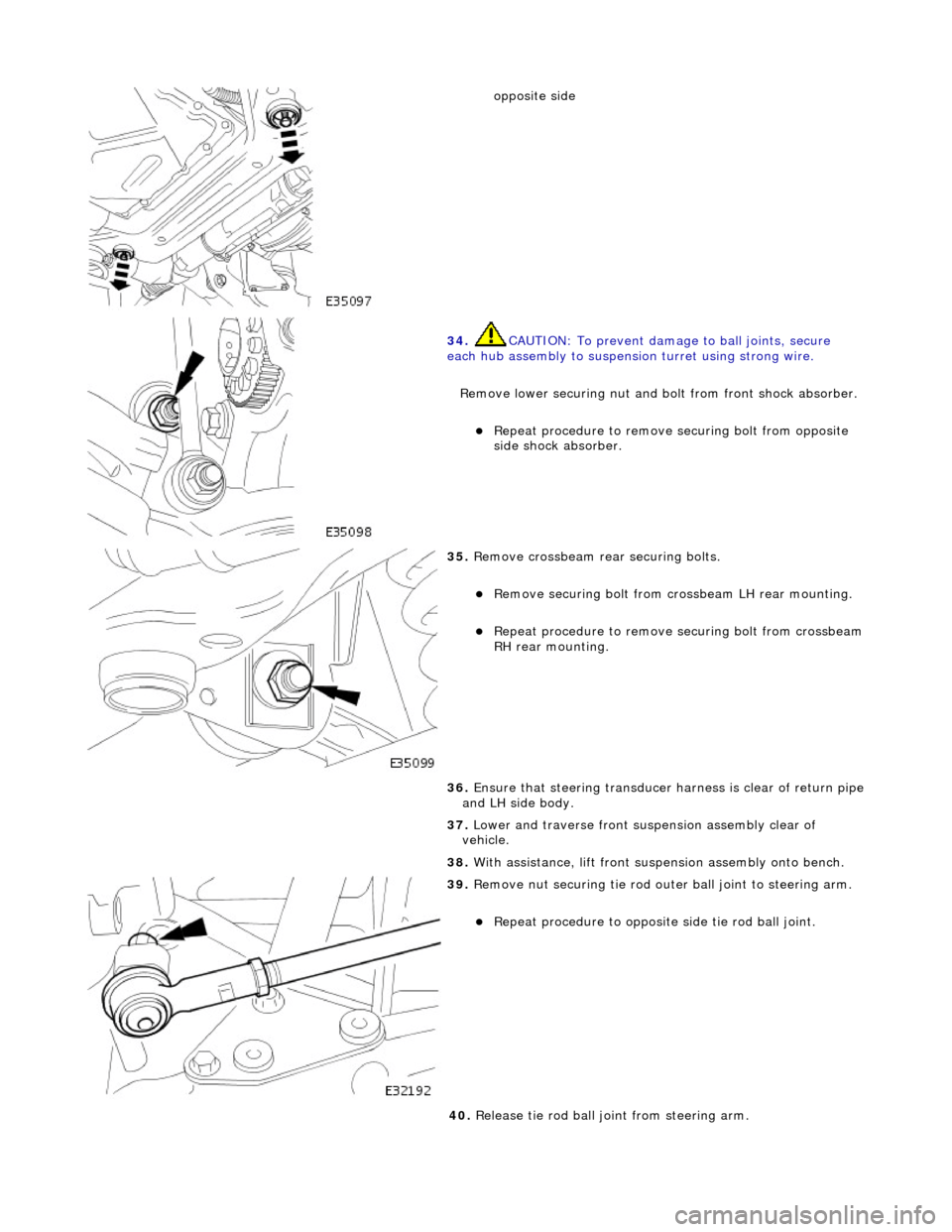
opposite side
34. CAUTION: To prevent damage to ball joints, secure
each hub assembly to suspensi on turret using strong wire.
Remove lower securing nut and bolt from front shock absorber.
Repeat procedure to remove securing bolt from opposite
side shock absorber.
35. Remove crossbeam rear securing bolts.
Remove securing bolt from crossbeam LH rear mounting.
Repeat procedure to remove securing bolt from crossbeam RH rear mounting.
36. Ensure that steering transducer harness is clear of return pipe
and LH side body.
37. Lower and traverse front suspension assembly clear of
vehicle.
38. With assistance, lift front suspension as sembly onto bench.
39. Remove nut securing tie rod oute r ball joint to steering arm.
Repeat procedure to opposite side tie rod ball joint.
40. Release tie rod ball joint from steering arm.