steering wheel adjustment JAGUAR X308 1998 2.G Workshop Manual
[x] Cancel search | Manufacturer: JAGUAR, Model Year: 1998, Model line: X308, Model: JAGUAR X308 1998 2.GPages: 2490, PDF Size: 69.81 MB
Page 61 of 2490
Suspension System - General Information - Front Camber and Caster
Adjust
ment
Gen
eral Procedures
• NOTE: Before any work is commenced, th e vehicle must be checked to establish that it conforms to the Jaguar original
specification, e.g. wheels, ti res, tire pressures, etc.
• NOTE: The vehicle must be unladen and the fuel tank full when measuring suspension geometry.
1.
Road test the vehicle to establish the exact nature of the
complaint, e.g. pulling to one side, wander.
2. Measure the suspension geometry, fill in the 'Suspension
Geometry Record Form', and co ntact Jaguar Technical Support
for assistance.
3. Technical Support will give advice on the course of action to be
taken to rectify the problem.
4. Each lower wishbone pivots on and is secured to the front
crossbeam by two fulcrum bolts. A circular eccentric flange
formed under the hexagonal head of each fulcrum bolt, has
raised graduation marks to indicate radial position. A washer
with a 'D' shaped hole locates on a flat on the threaded section
of each bolt. This ensures that the washer rotates with the bolt,
maintaining an eccentric position corresponding with the
flanged head. The outer face of the washer is punch marked,
ensuring correct instal lation with the chamfered face inwards.
This permits the washer to rotate freely in the crossbeam cam
reaction plate during a djustm ent. Each fulcrum bolt and
washer are secured by a self locking nut.
On rotation of the bolt, lateral movement of the eccentric flange
and washer is restricted by the cam plate faces, forcing the bolt
shank to move laterally in the crossbeam slots. Lateral
movement of the bolt shank re sults in corresponding inward
and outward movement of th e wishbone arm, effecting
adjustment of wh eel alignment.
Rotation of the front fulcrum bolt principally adjusts wheel
caster angle, with a small amount of camber angle change.
Adjustment of the rear fulcrum bo lt mainly alters wheel camber
angle with a small amount of caster angle change.
On vehicles with VIN up to 833124, fulcrum bolt eccentric
flanges have raised graduation marks representing 15 degree
increments of bolt rotati on from 0 to 90 degrees.
On vehicles with VIN from 833125, the fulcrum bolt graduation
marks represent bolt shank ho rizontal movement in 1mm
increments from 0 to 3mm.
The upper wishbone and fulcrum shaft are not adjustable and
play no part in steering geometry adjustment.
Page 62 of 2490
Suspension System - General Information - Front Camber
, Caster and Toe
Adjustment
Gen e
ral Procedures
1.
NOTE: Before checking or adju sting any alignment, examine
the vehicle for curb impact dama ge on wheels and subsequent
damage to steering and suspension components.
• NOTE: Wheel alignment must no t be carried out with a space
saver wheel installed on any of the hubs.
• NOTE: Before carrying out any ch ecking or adjustment of wheel
alignment, ensure that the vehicl e wheels, tires and tire pressures
are to Jaguar specification.
• NOTE: Position steering wheel in straight ahead position before
adjusting front wheel toe evenly on both tie rods to maintain
centralization of steering wheel.
Position alignment checking equipment on vehicle and following
equipment manufacturer's instructions, check and if necessary
adjust to Specifications in Section 204-01.
2. Check and as necessary adjust front wheel caster. Refer to
57.65.05.
3. Check and as necessary adjust front wheel camber. Refer to
57.65.06.
4. Check and as necessary adjust fr ont wheel alignment. Refer to
57.65.01.
Page 63 of 2490
Suspension System - General Infor
mation - Front Toe Adjustment
Gen
eral Procedures
1.
NOTE: Before checking or adju sting front wheel alignment,
examine the vehicle for curb impact damage on wheels and
subsequent damage to steering and suspension components.
• NOTE: Wheel alignment must no t be carried out with a space
saver wheel installed on any of the hubs.
• NOTE: Before carrying out any ch ecking or adjustment of wheel
alignment, ensure that the vehicl e wheels, tires and tire pressures
are to Jaguar specification.
• NOTE: Position steering wheel in straight ahead position before
adjusting front wheel toe evenly on both tie rods to maintain
centralization of steering wheel.
Position alignment checking equipment on road wheels and
following equipment manufacturer's instructions, check and if
necessary adjust front wheel toe to Specifications in Section
204-01.
Page 310 of 2490
oc
curs only with the parking brake, th
e concern is in the rear brake system.
If the concern becomes evident during this check, verify it fits the description given before the road test. If the concern is
not evident, attempt to duplicate the condition using the information from the description.
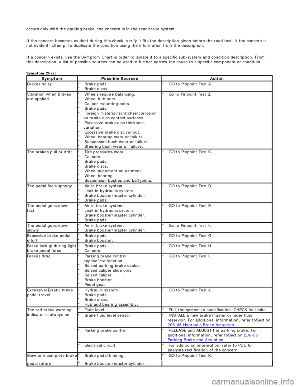
If a concern exists, use the Symptom Chart in order to isolate it to a specific sub-system and condition description. From
this description, a list of possible sources can be used to further narrow the cause to a specific component or condition.
Sym
ptom Chart
Sy
m
ptom
Possib
l
e Sources
Acti
o
n
Brakes
n
oisy
Brake pads.
Brake di
scs
.
*
*
GO to Pinpoint
Tes
t A.
*
Vibration wh
en brakes
are applied
Wh eels require bala
ncing.
Wheel hub nuts.
Caliper mounting bolts.
Brake pads.
Foreign material/scr atches/corrosion
on brake disc contact surfaces. Excessive brake disc thickness
variation. Excessive brake disc runout.
Wheel bearing wear or failure.
Suspension bush wear or failure.
Steering bush wear or failure.
*
*
*
*
*
*
*
*
*
*
Go to Pinpoint
Tes
t B.
*
The brakes pull or drif tTire pressures/wear.
Calipers.
Brake pads.
Brake di
scs.
Wheel alignment adjustment.
Wheel bearing.
Suspension bushes and ball joints.
*
*
*
*
*
*
*
GO to Pinpoint
Tes
t C.
*
The pedal feels spongyAir i
n brake system.
Leak in hydraulic system.
Brake booster/master cylinder.
Brake pads.
*
*
*
*
GO to Pinpoint Tes
t D.
*
The pedal goes down
fa s
t
Ai
r i
n brake system.
Leak in hydraulic system.
Brake booster/master cylinder.
Brake pads.
*
*
*
*
GO to Pinpoint
Tes
t E.
*
The pedal goes down
slowl yAir i
n brake system.
Brake booster/master cylinder.
*
*
Go to Pinpoint
Tes
t F.
*
Excessive brake pedal
effor tBrake pads.
Brake booster.
*
*GO to Pinpoint
Tes
t G.
*
Brake lockup du ring ligh
t
brake pedal force
Brake pads.
Calipers.
*
*GO to Pinpoint
Tes
t H.
*
Brakes d r
ag
Parkin
g brake con
trol
applied/malfunction. Seized parking brake cables.
Seized caliper slide pins.
Seized caliper.
Brake booster.
Pedal gear.
*
*
*
*
*
*
GO to Pinpoint
Tes
t I.
*
Exce ssi
ve/Erratic brake
pedal travel
Hydrau li
c system.
Brake pads.
Brake discs.
Hub and bearing assembly.
*
*
*
*
GO to Pinpoint
Tes
t J.
*
The red brak e warning
indi
cator is always on
Fl
ui
d level.
*
F I
LL the system to specification. CHECK for leaks.
*
Brake flu i
d level sensor.
*
I N
STALL a new brake master cylinder fluid
reservoir. For additional in formation, refer toSection
206
-0 6
Hydraulic Brake Actuation
.
*
Parkin
g brake con
trol.
*
REL
E
ASE and ADJUST the parking brake. For
additional information, refer toSection 206
-05
Parkin g Brake an
d Actuation
.
*
E
l
ectrical circuit.
*
F or additional
information, refer to PDU for
analysis/rectification of the concern.
*
Sl
ow or i
ncomplete brake
Brake peda
l binding.
*
GO to Pinpoint Tes
t K.
*
pedal retu rnBr
ake booster/master cylinder.
*
Page 460 of 2490
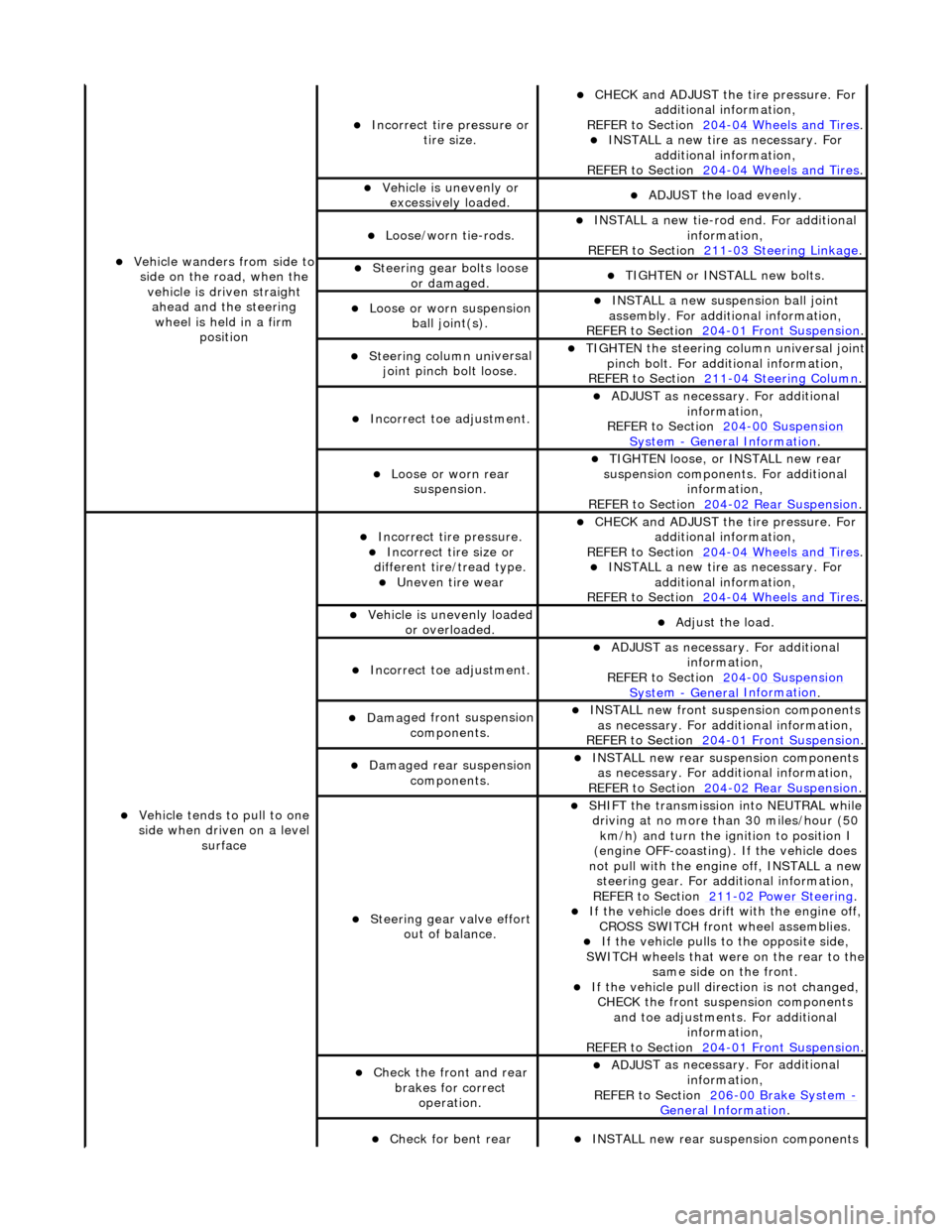
Vehicl
e wanders from side to
side on the road, when the vehicle is driven straight ahead and the steering wheel is held in a firm position
Incorrect ti re
pressure or
tire size.
CHECK and ADJ
UST the tire pressure. For
additional information,
REFER to Section 204
-0 4
Wheels and Tires
. IN
ST
ALL a new tire as necessary. For
additional information,
REFER to Section 204
-0 4
Wheels and Tires
.
Vehi
cl
e is unevenly or
excessively loaded.
A D
JUST the load evenly.
Loose/worn ti
e-
rods.
INST
ALL a ne
w tie-rod
end. For additional
information,
REFER to Section 211
-0 3
Steering Linkage
.
Steeri
ng gear bolts loose
o
r damaged.
TIGHTE
N or INSTALL
new bolts.
Loose or worn suspensi
on
ball jo
int(s).
INST
ALL a ne
w suspension ball joint
assembly. For additional information,
REFER to Section 204
-01 Fron
t Suspension
.
Steeri
ng column uni
versal
joint pinch bolt loose.
TI G
HTEN the steering column universal joint
pinch bolt. For additi onal information,
REFER to Section 211
-0 4
Steering Column
.
Incorre
ct
toe adjustment.
ADJUS
T as necessary. For additional
information,
REFER to Section 204
-00 Sus
pension
Sy
ste
m
- General
Information
.
Loose or worn rear
susp
ension.
TIGHTEN
loose, or IN
STALL new rear
suspension components. For additional information,
REFER to Section 204
-0 2
Rear Suspension
.
Vehicle t
e
nds to pull to one
side when driven on a level surface
Incorrect ti
re pressure.
Incorrect
ti
re size or
different tire/tread type.
Uneven tire wear
CHECK and ADJ
UST the tire pressure. For
additional information,
REFER to Section 204
-0 4
Wheels and Tires
. IN
ST
ALL a new tire as necessary. For
additional information,
REFER to Section 204
-04
Wheels and Tires
.
Vehicl
e is unevenly loaded
or overloaded.
Adjust the load
.
Incorre
ct
toe adjustment.
ADJUS
T as necessary. For additional
information,
REFER to Section 204
-00 Sus
pension
Sy
ste
m
- General
Information
.
Dam
a
ged front suspension
components.
I N
STALL new front suspension components
as necessary. For addi tional information,
REFER to Section 204
-01 Fron
t Suspension
.
Damaged rear
suspen
sion
components.
INST ALL ne
w rear suspension components
as necessary. For addi tional information,
REFER to Section 204
-0 2
Rear Suspension
.
Steeri
ng gear val
ve effort
out of balance.
SHIF T the
transmission into NEUTRAL while
driving at no more than 30 miles/hour (50 km/h) and turn the ignition to position I
(engine OFF-coasting). If the vehicle does
not pull with the engine off, INSTALL a new steering gear. For additional information,
REF E
R to Section 211
-0
2
Power Steering
. If t
he
vehicle does drift with the engine off,
CROSS SWITCH front wheel assemblies.
If the
vehicle pulls to
the opposite side,
SWITCH wheels that were on the rear to the
same side on the front.
If the v
ehicle pull dire
ction is not changed,
CHECK the front susp ension components
and toe adjustments. For additional information,
REFER to Section 204
-01 Fron
t Suspension
.
Chec
k
the front and rear
brakes for correct operation.
ADJUS
T as necessary. For additional
information,
REFER to Section 206
-0 0
Brake System
-
General Informati on.
Check fo
r bent rear
INST
ALL ne
w rear suspension components
Page 461 of 2490
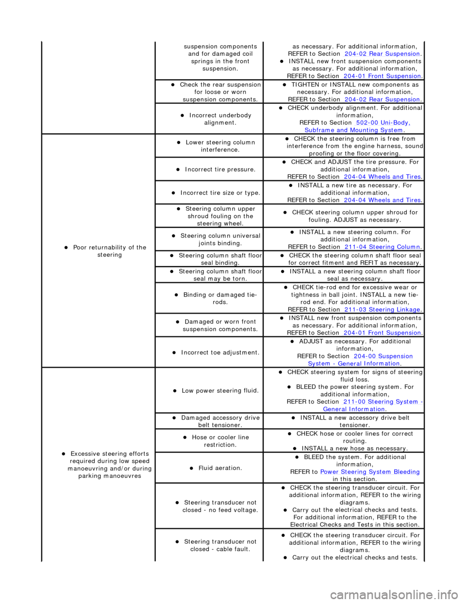
sus
pension components
and for damaged coil springs in the front suspension.
as necessary. For addi tional information,
REF
ER to Section 204
-0
2 Rear Suspension
. I
NSTALL new front suspension components
as necessary. For addi tional information,
REFER to Section 204
-01
Front Suspension
.
Chec
k the rear suspension
for loose or worn
suspension components.
TIGHTE
N or INSTALL new components as
necessary. For additi onal information,
REFER to Section 204
-0
2 Rear Suspension
.
Incorre
ct underbody
alignment.
CHECK
underbody alignment. For additional
information,
REFER to Section 502
-00
Uni
-Body, Subframe and M
ounting System
.
Poor r
eturnability of the
steering
Lower steeri
ng column
interference.
CHECK
the steering co
lumn is free from
interference from the en gine harness, sound
proofing or the floor covering.
Incorrect
tire pressure.
CHECK
and ADJUST the tire pressure. For
additional information,
REFER to Section 204
-0
4 Wheels and Tires
.
Incorrect
tire size or type.
IN
STALL a new tire as necessary. For
additional information,
REFER to Section 204
-0
4 Wheels and Tires
.
Steeri
ng column upper
shroud fouling on the steering wheel.
CHECK
steering column upper shroud for
fouling. ADJUST as necessary.
Steeri
ng column universal
joints binding.
IN
STALL a new steering column. For
additional information,
REFER to Section 211
-0
4 Steering Column
.
Steeri
ng column shaft floor
seal binding.
CHE
CK the steering column shaft floor seal
for correct fitm ent and REFIT as necessary.
Steeri
ng column shaft floor
seal may be torn.
IN
STALL a new steering column shaft floor
seal as necessary.
Bin
ding or damaged tie-
rods.
CHECK
tie-rod end for excessive wear or
tightness in ball joint. INSTALL a new tie- rod end. For additional information,
REFER to Section 211
-0
3 Steering Linkage
.
D
amaged or worn front
suspension components.
I
NSTALL new front suspension components
as necessary. For addi tional information,
REFER to Section 204
-01
Front Suspension
.
Incorre
ct toe adjustment.
AD
JUST as necessary. For additional
information,
REFER to Section 204
-00
Suspension
Sy
stem
- General
Information
.
Excessive steeri
ng efforts
required during low speed
manoeuvring and/or during parking manoeuvres
Low power steer
ing fluid.
CHE
CK steering system
for signs of steering
fluid loss.
BLEE
D the power steering system. For
additional information,
REFER to Section 211
-0
0 Steering System
- General Informati
on
.
Damaged accessory driv
e
belt tensioner.
INST
ALL a new accessory drive belt
tensioner.
Hose or cooler li
ne
restriction.
CHECK
hose or cooler lines for correct
routing.
INST
ALL a new hose as necessary.
Fl
uid aeration.
BLEE
D the system. For additional
information,
REFER to Power Steering System Bleeding
in t
his section.
Steeri
ng transducer not
closed - no feed voltage.
CHECK
the steering transducer circuit. For
additional information, REFER to the wiring diagrams.
Carry ou
t the electrical checks and tests.
For additional information, REFER to the
Electrical Checks and Tests in this section.
Steeri
ng transducer not
closed - cable fault.
CHECK
the steering transducer circuit. For
additional information, REFER to the wiring diagrams.
Carry ou
t the electrical checks and tests.
Page 497 of 2490

Locate the ti
e rod end into the steering arm.
Inst
all a new nut.
Tigh
ten the nut to 22-28 Nm.
12
.
NOTE: Make sure the steering wheel and wheel and tire
assemblies are in the straight ah ead position before fitting the
steering column lower shaft.
Attach the steering column lower shaft.
1. Attach the steering column lower shaft.
2. Install the steering column lower shaft retaining bolt.
1. Tighten to 28 - 34 Nm
.
3
. Tighten to 28 - 34 Nm.
13. Fit a new power steering fluid re servoir, refill with new power
steering fluid and blee d air from the system.
For additional information, refer to: Power Steering System
Fillin
g and Bleeding
(211-00 Steering System - General
Information, Gene ral Procedures).
14. Check and adjust the front toe.
For additional information, refer to: Front Toe Adjustment
(204-00 Suspen
sion System -
General Information, General
Procedures).
Page 503 of 2490

Steering
Linkage - Steering Linkage
Descriptio
n and Operation
Parts List
The left- and right-hand tie rod assemblies:
T
ransmit steering forces from the steering rack to the st
eering arms which are integral with the vertical links.
Comprise the tie rod, inner
ball joint,
outer tie rod end and outer ball joint.
P
rovide front road wheel toe setting by adju
stment of the threaded outer tie rod ends.
• NOTE: Steering geometry adjustments must only be carried out wi th the vehicle on turn plates to allow the wheels to move
during adjustment.
The left- and right-hand steering rack gaiters:
Are
installed between the steering rack and the tie bars.
Are
of the concertina type.
R
etain lubricant and prevent th
e ingress of foreign matter.
P
ermit movement of the steering rack and tie rods.
ItemPa
rt Number
Descript
ion
1—St
eering rack assembly
2—St
eering rack gaiter
3—I
nner ball joint
4—Tie
rod
5—O
uter tie rod end
6—Lo
ck-nut
7—Oute
r ball joint
8—O
uter ball joint nut
Page 507 of 2490
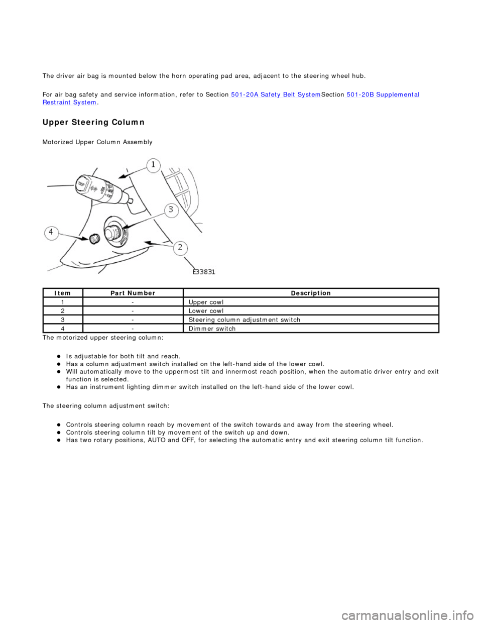
The driver air bag is moun
ted below the horn operat
ing pad area, adjacent to the steering wheel hub.
For air bag safety and service information, refer to Section 501
-20A Safety Belt
System
Sectio
n
501
-2
0B Supplemental
Re
straint System
.
Upper Steering Column
Motorized Upper Colu
mn Assembly
The motorized upper steering column:
Is adjustable for both til
t and reach.
Has a col
umn adjustment switch installed on
the left-hand side of the lower cowl.
W
ill automatically move to the uppermost tilt and innermost reach position, when the automatic driver entry and exit
function is selected.
Has an instrument li
ghti
ng dimmer switch installed on the left-hand side of the lower cowl.
The steering column adjustment switch:
Controls steeri
ng column reach by
movement of the switch towards an d away from the steering wheel.
Controls steeri
ng column tilt by mo
vement of the switch up and down.
Has two
rotary positions, AUTO and OFF, for selecting the
automatic entry and exit steering column tilt function.
It
em
Par
t Number
De
scription
1-Upper
cowl
2-Lower cowl
3-Ste
ering column adjustment switch
4-Di
mmer switch
Page 508 of 2490
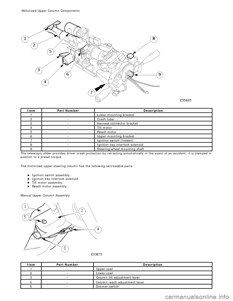
The te
lescopic slider provides driver crash
protection by retracting automatically in the event of an accident; it is clamped in
position to a preset torque.
The motorized upper steering column has the following serviceable parts:
Igniti
on switch assembly.
Igni
ti
on key interlock solenoid.
Ti
lt
motor assembly.
Reach motor assembly.
Manu al Upper Column Assembly
Ite
m
Par
t
Number
De
scr
iption
1-L
o
wer mounting bracket
2-Crash tube
3-Harnes
s c
onnector bracket
4-Tilt motor
5-Reach m
otor
6-Upper
moun
ting bracket
7-Ignition switc
h
(hidden)
8-Igni
ti
on key interlock solenoid
9-S
t
eering wheel mounting shaft
It
e
m
Par
t
Number
De
scr
iption
1-Upper
cowl
2-Lower cowl
3-Colu
mn tilt adjustment lever
4-Col
u
mn reach adjustment lever
5-Di
mm
er switch
Motorized Upper Co
lumn Components