Oil JAGUAR X308 1998 2.G User Guide
[x] Cancel search | Manufacturer: JAGUAR, Model Year: 1998, Model line: X308, Model: JAGUAR X308 1998 2.GPages: 2490, PDF Size: 69.81 MB
Page 47 of 2490

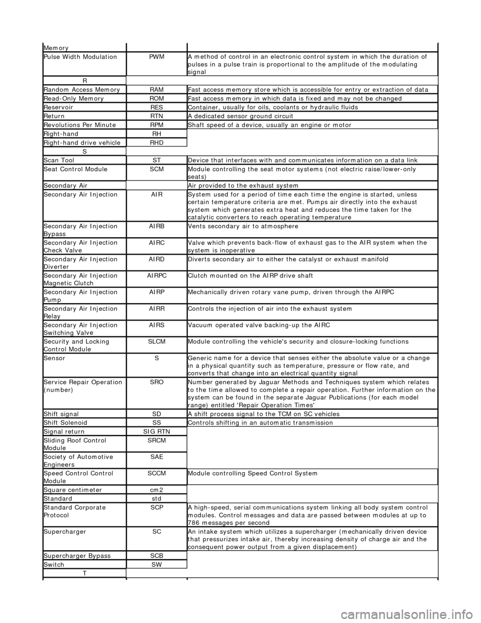
Mem
ory
Pulse Width ModulationPW
M
A
method of control in an electronic co
ntrol system in which the duration of
pulses in a pulse train is proportional to the amplitude of the modulating
signal
R
Ran
dom Access Memory
RAMF
ast access memory store which is accessible for entry or extraction of data
Re
ad-Only Memory
RO
M
F
ast access memory in which data
is fixed and may not be changed
Re
servoir
RESContaine
r, usually for oils,
coolants or hydraulic fluids
Re
turn
RTNA
dedicated sensor ground circuit
R
evolutions Per Minute
RP
M
Shaft speed o
f a device, us
ually an engine or motor
R
ight-hand
RH
Right-hand drive veh
icle
RHD
S
Scan T
ool
STDe
vice that interfaces with and comm
unicates information on a data link
Se
at Control Module
SCMModule
controlling the seat motor systems (not electric raise/lower-only
seats)
Secon
dary Air
Air pro
vided to the exhaust system
Secon
dary Air Injection
AIRSy
stem used for a period of time each
time the engine is started, unless
certain temperature criter ia are met. Pumps air directly into the exhaust
system which generates extra heat and reduces the time taken for the
catalytic converters to reach operating temperature
Secon
dary Air Injection
Bypass
AIRBVents secon
dary air to atmosphere
Secon
dary Air Injection
Check Valve
AIRCValve wh
ich prevents back-flow of exhaust gas to the AIR system when the
system is inoperative
Secon
dary Air Injection
Diverter
AIRDD
iverts secondary air to either
the catalyst or exhaust manifold
Secon
dary Air Injection
Magnetic Clutch
AIRP
C
Clu
tch mounted on the AIRP drive shaft
Secon
dary Air Injection
Pump
AIRPMe
chanically driven rotary vane
pump, driven through the AIRPC
Secon
dary Air Injection
Relay
AIRRCont
rols the injection of air into the exhaust system
Secon
dary Air Injection
Switchin
g Va
lve
AIRSV
acuum operated valve backing-up the AIRC
Secu
rity and Locking
Control Module
SLCMModul
e controlling the vehicle's security and closure-locking functions
SensorSGeneri
c name for a device
that senses either the absolute value or a change
in a physical quantity su ch as temperature, pressure or flow rate, and
converts that change into an electrical quantity signal
Servic
e Repair Operation
(number)
SRONu
mber generated by Jaguar Methods
and Techniques system which relates
to the time allowed to complete a repair operation. Further information on the
system can be found in the separate Jaguar Publications (for each model
range) entitled 'Repair Operation Times'
Shif
t signal
SDA
shift process signal to the TCM on SC vehicles
Shif
t Solenoid
SSControls shi
fting in an automatic transmission
Si
gnal return
SIG RTN
Slidin
g Roof Control
Module
SRCM
Society of Automotive
Engineers
SAE
Speed
Control Control
Module
SCCMModule con
trolling Speed Control System
Square c
entimeter
cm
2
Stan
dard
std
Stan
dard Corporate
Protocol
SCPA
high-speed, serial communications system linking all body system control
modules. Control messages and data ar e passed between modules at up to
786 messages per second
SuperchargerSCAn in
take system which utilizes a supercharger (mechanically driven device
that pressurizes intake air, thereby in creasing density of charge air and the
consequent power output from a given displacement)
Supercharger
Bypass
SCB
SwitchSW
T
Page 48 of 2490

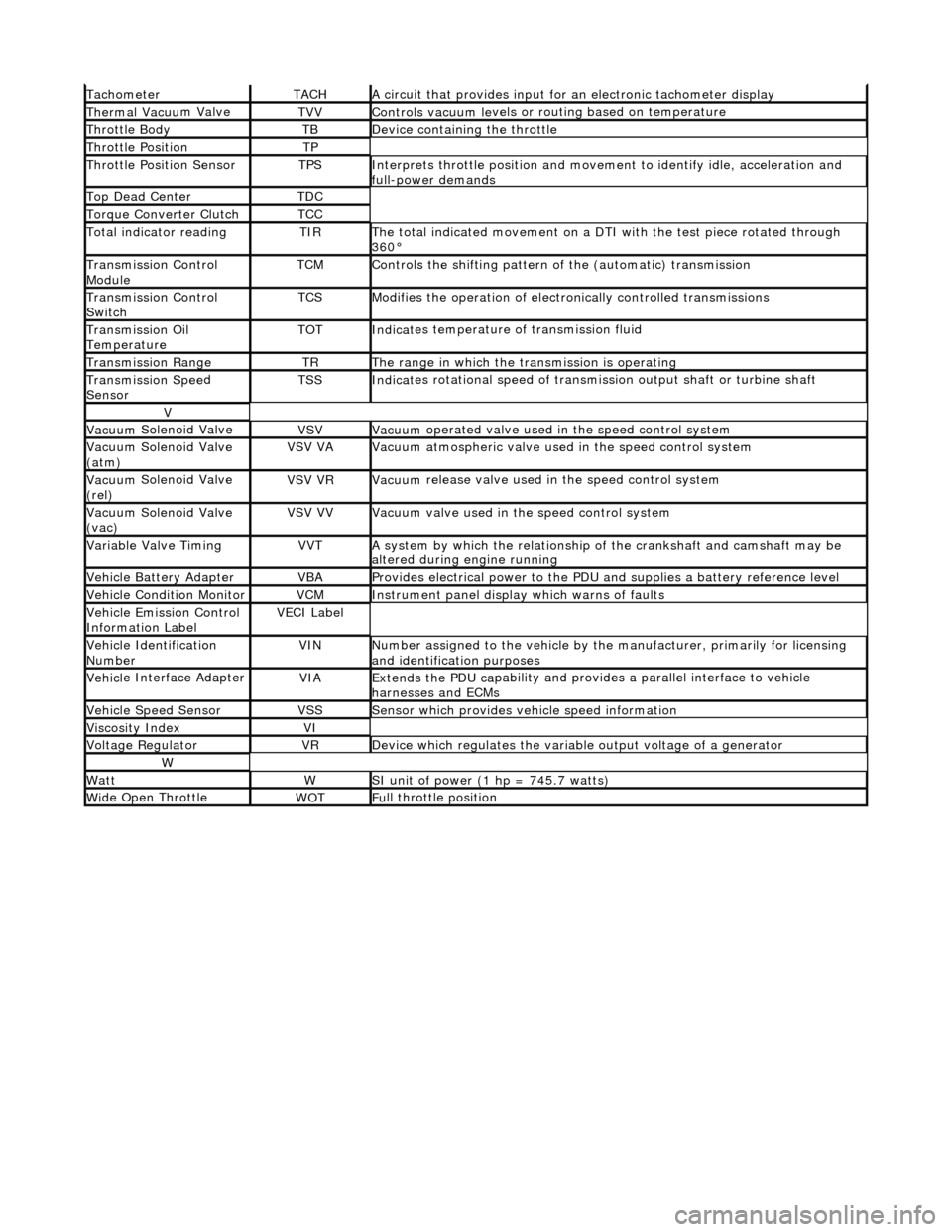
Tacho
meter
TACHA
ci
rcuit that provides input for
an electronic tachometer display
Thermal Vacuu
m Valve
TVVControls vacuum l
e
vels or
routing based on temperature
Throttle
Body
TBDe
vi
ce containing the throttle
Throttl
e
Position
TP
Throttl
e
Position Sensor
TPSInterprets throttl
e
position and movement to iden tify idle, acceleration and
full-power demands
Top Dead CenterTDC
Torque Converter C
lutch
TCC
To
tal
indicator reading
TIRThe t
o
tal indicated movement on a DTI with the test piece rotated through
360В°
Transm
ission Control
Module
TCMControls
the shifting pattern
of the (automatic) transmission
Transm
ission Control
Switch
TCSModifi es
the operation of electronically controlled transmissions
Transmission Oil
TemperatureTOTIndi
cat
es temperature of transmission fluid
Transmission RangeTRThe ran
g
e in which the transmission is operating
Transmission Spe
e
d
Sensor
TSSIndi cat
es rotational speed of transmission output shaft or turbine shaft
V
Vacuu
m
Solenoid Valve
VSVVacuu
m
operated valve used in the speed control system
Vacuu
m
Solenoid Valve
(atm)
VSV VAVacuu m
atmospheric valve used in the speed control system
Vacuu
m
Solenoid Valve
(rel)
VSV VRVacuu m
release valve used in the speed control system
Vacuu
m
Solenoid Valve
(vac)
VSV VVVacuu m
valve used in the speed control system
Variable Valve TimingVVTA
s
ystem by which the relationship of the crankshaft and camshaft may be
altered during engine running
Vehi cl
e Battery Adapter
VBAProvide
s
electrical power to the PDU
and supplies a battery reference level
Vehicl
e Condition Monitor
VCMInst
rum
ent panel display which warns of faults
Ve
hic
le Emission Control
Information Label
VECI Label
Vehi cl
e Identification
Number
VINN u
mber assigned to the vehicle by the manufacturer, primarily for licensing
and identification purposes
Vehi cl
e Interface Adapter
VIAExtends the
PDU ca
pability and provid
es a parallel interface to vehicle
harnesses and ECMs
Vehicle Spe e
d Sensor
VSSSens
or which provides ve
hicle speed information
Viscosity In
dexVI
Voltage RegulatorVRDe
vice which regulates the variable output voltage of a generator
W
Wat
tWSI unit of power (1 hp = 7
45.7 watts)
W
i
de Open Throttle
WO
TFu
ll throttle position
Page 70 of 2490

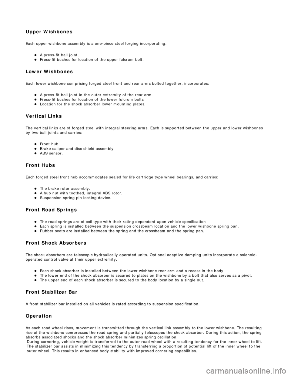
Upper
Wishbones
Each
upper wi
shbone assembly is a on
e-piece steel forging incorporating:
пЃ¬A pres
s-fit ball joint.
пЃ¬Press-fi
t bushes for location of the upper fulcrum bolt.
Lower Wishbones
Each l
o
wer wishbone comprising
forged steel front and rear arms bolted together, incorporates:
пЃ¬A p
ress-fit ball joint in the outer extremity of the rear arm.
пЃ¬Press-f
i
t bushes for location of the lower fulcrum bolts
пЃ¬Locati
on for the shock absor
b
er lower mounting plates.
Vertica l Links
The vertical
links are of forged steel
wi
th integral steering arms. Each is suppo rted between the upper and lower wishbones
by two ball joints and carries:
пЃ¬Front hub
пЃ¬Brake ca
liper and disc shield assembly
пЃ¬ABS se
nsor
.
Front Hub
s
Each f
o
rged steel front hub accommodates sealed for life cartridge
type wheel bearings, and carries:
пЃ¬The brake rotor assembl
y.
пЃ¬A
h
ub nut with toothed, integral ABS rotor.
пЃ¬Su
s
pension spring pi
n locking device.
Front Road
Springs
пЃ¬The road spri
ng
s are of coil type with their
rating dependent upon vehicle specification
пЃ¬Ea
ch spring is installed between the suspension crossbeam location and the lower wishbone spring pan.
пЃ¬Ru
bber seats ar
e installed betw
een the spring and the crossb eam and the spring pan.
Front Shock A
bsorbers
Th
e
shock absorbers are telescopic hydrau
lically operated units. Optional adaptive damping units incorporate a solenoid-
operated control valve at their upper extremity.
пЃ¬Each shoc
k absorber is installed between the lowe
r wishbone rear arm and a recess in the body.
пЃ¬The l
o
wer end of the shock absorber is se
cured to plates on the wishbone by a bolt that also serves as a pivot.
пЃ¬The u
pper en
d of each shock absorber is secured to the body location by a single nut.
Front Sta
b
ilizer Bar
A
front stabil
izer bar installed on all vehicles
is rated according to suspension specification.
Opera
tion
As each road wheel r
i
ses, move
ment is transmitted through the vertical link assembly to the lower wishbone. The resulting
rise of the wishbone compresses the road spring and partially telescopes the shock absorber. During this action, the spring
absorbs associated shocks and the shock absorber minimizes sprin
g os c
illation.
Du
ring cornering, vehicle weight
is transferred to the outer road wheel with a resulting tendency for the inner wheel to lift.
The stabilizer bar assists in minimizing this tendency by transf erring a proportion of potential lift of the inner wheel to the
outer wheel. This result s in enhanced body stability with improved corner ing capabilities.
Page 118 of 2490

6. Re
lease stabilizer bar from link arms.
пЃ¬R
e
move stabilizer bar to link arm ball joint securing nut.
пЃ¬Repeat operation
at opp
osite
end of stabilizer bar.
7. Slacken stabil
izer bar securing bolts.
8. NO
TE: On vehicles fitted with an engine oil cooler, it may be
necessary to release the stabilizer bar from each ball joint in turn
to achieve the required cl earance from cooler pipes.
Remove stabilizer bar from crossbeam.
пЃ¬R e
move stabilizer bar securing bolts.
пЃ¬R
e
move stabilizer bar and mounting brackets from
crossbeam.
9. Remove mounting brackets and rubbers from stabilizer bar.
Page 123 of 2490

I
nstallation
6.
R
elease stabilizer bar from link arms.
пЃ¬R
emove nut securing stabilizer bar to link.
пЃ¬R
elease link arm from stabilizer bar.
пЃ¬Repeat operation
at opposite
end of stabilizer bar.
7. N
OTE: On vehicles fitted with an engine oil cooler, it may be
necessary to release the stabilizer bar from each ball joint in turn
to achieve the required cl earance from cooler pipes.
Remove stabilizer bar from crossbeam.
пЃ¬R
emove stabilizer bar securing bolts.
пЃ¬R
emove stabilizer bar mountin
g brackets and remove bar
from crossbeam.
8. Re
move mounting brackets and
rubbers from stabilizer bar.
1. CAUTION: Make sure the Ca strol NTR grease is only
applied to the inner surface of the mounting bushes. Failure to
follow this instruction may affect the retention of the bushes in
the retaining brackets.
Page 183 of 2490

13
.
Using the special tools 204-179-1, secure the upper mounting
to the spring.
14
.
Using a jack, retract the shock absorber through the
wishbone aperture.
15
.
Position a bolt through the spring coils and shock absorber
lower-bush, to temporarily locate the shock absorber.
16. Partially lower the jack for a ccess to the top of the shock
absorber.
17. On vehicles with adaptive damping:
пЃ¬Di
sconnect the shock absorber electrical connector by
pressing the lugs down and pulling the connector up.
Page 184 of 2490

18. Lower and remove the
jack.
19. Remove the shock absorber an d spring assembly from the
vehicle and place the assembly on a work bench.
20. Clean the upper mounting spring location.
21 . Remove the
pigtail seat and cl
ean the wishbone lower spring
location.
22 . W
ith assistance, manually compress the shock absorber and
withdraw the bolt from the spring coils.
23 . R
emove the shock absorber from the upper mounting.
пЃ¬Posi
ti
on a wrench on the shock absorber shaft flats to
prevent rotation (wrench in socket on vehicles with
adaptive damping).
пЃ¬R e
move the shock absorber
upper retaining nut.
пЃ¬Remove the u
pper washer and isolator.
24. Remove the special tools 204-179-1 and remove the upper
mounting from the spring.
Page 186 of 2490

4. Position the spri ng
upper mounting assembly on to the shock
absorber.
пЃ¬Apply a th in
coat of grease to the upper mounting bush.
пЃ¬E
n
sure that the washer, lo
wer isolator and bush are
correctly positioned on the shock absorber shaft.
пЃ¬Po si
tion the shock absorber shaft in the upper mounting.
5. Sec
ure the top of the shock ab
sorber to the upper mounting.
пЃ¬Install the spri
ng upper isolator.
пЃ¬Inst
al
l the upper washer.
пЃ¬In
s
tall but do not tighten the locknut on to the shock
absorber.
6. Manu ally r
etract the shock abso
rber and place a bolt through
the spring coils and the sh ock absorber lower-bush.
7. Secure the shock absorber to the upper mounting.
пЃ¬Positi
on a wrench on the shock absorber shaft flats to
prevent rotation (wrench in socket on vehicles with
adaptive damping).
пЃ¬Tigh te
n the shock absorber upper lock nut to 30-40 Nm
(16-18 Nm on vehicles with adaptive damping).
Page 193 of 2490

I
nstallation
5.
NOTE
: With assistance make sure the tool is aligned.
Using special tools, slowly push the bush from the shock
absorber.
1. N
OTE: Make sure the bush is cl
ean and free from oil or grease.
• NOTE: Use a suitable lubricant to allow the bush to locate into
the special tool.
Locate the new bush in the special tool.
2. N
OTE: Make sure the damper is clean and free from grease or
oil and is not damaged prior to pushing in the new bush.
• NOTE: Make sure the shock absorb er and bush are placed in the
correct orientation.
Using the special tools, align the bush to the shock absorber.
3. NOTE: Make sure correct alignment is maintained.
Slowly push the bush into the shock absorber until the tool
Page 198 of 2490

13. U
sing the special tools 204-179-1, secure the upper mounting
to the spring.
14 . Using a jack, retract the sho
ck absorber through the
wishbone aperture.
15 . Posi
tion a bolt through the spring coils and shock absorber
lower-bush, to temporarily locate the shock absorber.
16. Partially lower the jack for a ccess to the top of the shock
absorber.
17. On vehicles with adaptive damping:
пЃ¬Disc
onnect the shock absorber electrical connector by
pressing the lugs down and pulling the connector up.