fuel diagram JAGUAR X308 1998 2.G User Guide
[x] Cancel search | Manufacturer: JAGUAR, Model Year: 1998, Model line: X308, Model: JAGUAR X308 1998 2.GPages: 2490, PDF Size: 69.81 MB
Page 1224 of 2490
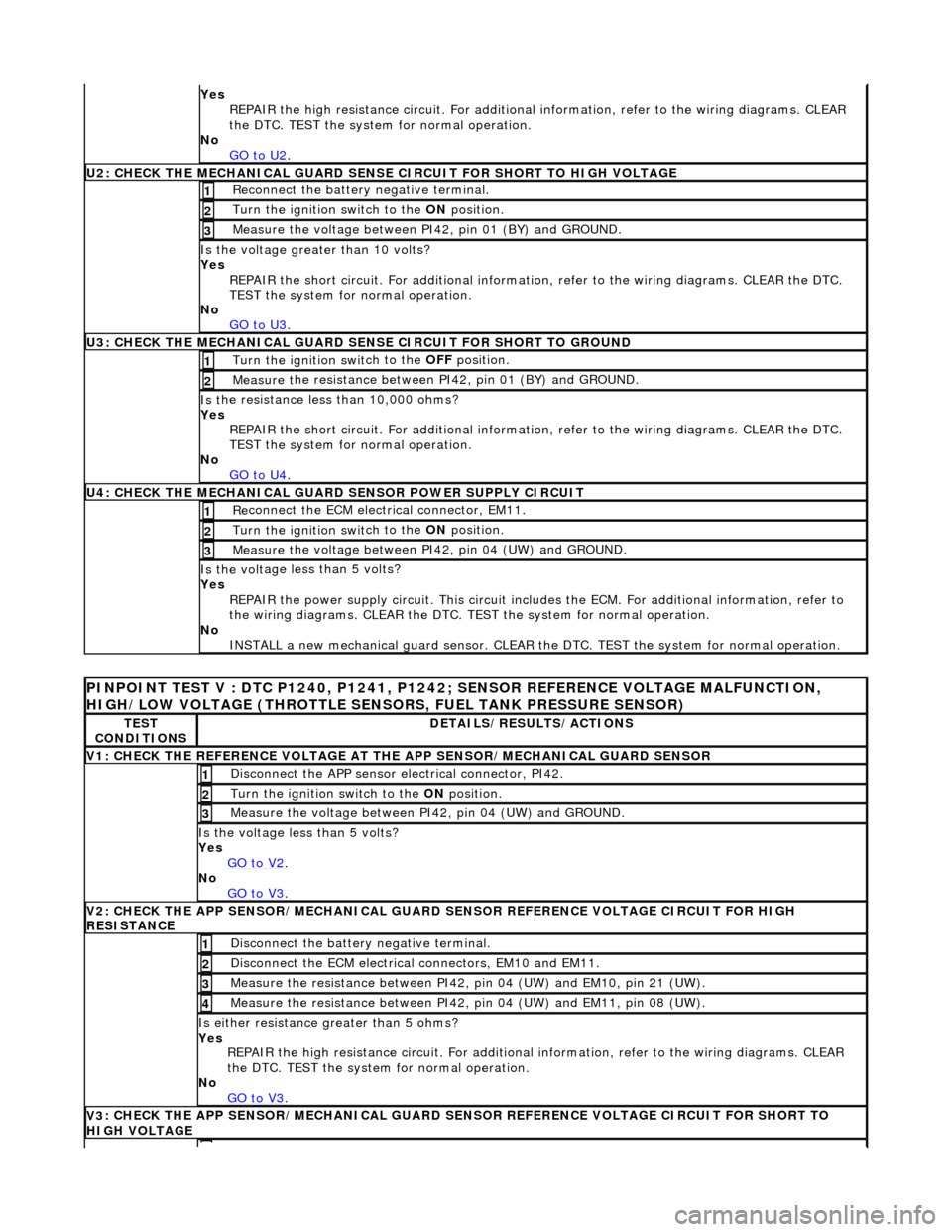
Yes
R
EPAIR the high resistance circui
t. For additional information, refer to the wiring diagrams. CLEAR
the DTC. TEST the system for normal operation.
No GO to U2
.
U2: CHECK T H
E MECHANICAL GUARD SENSE
CIRCUIT FOR SHORT TO HIGH VOLTAGE
Re
connect the battery negative terminal.
1
Turn the ignition swi
t
ch to the ON
position.
2
Measure t
he voltage between PI42, pin 01 (BY) and GROUND.
3
Is the volt
age greater than 10 volts?
Yes REPAIR the short circuit. For addi tional information, refer to the wiring diagrams. CLEAR the DTC.
TEST the system for normal operation.
No GO to U3
.
U3: CHECK T H
E MECHANICAL GUARD SE
NSE CIRCUIT FOR SHORT TO GROUND
Turn the ignition swit
ch to the OFF
position.
1
Measure t
he resistance between PI42, pin 01 (BY) and GROUND.
2
Is
t
he resistance less than 10,000 ohms?
Yes REPAIR the short circuit. For addi tional information, refer to the wiring diagrams. CLEAR the DTC.
TEST the system for normal operation.
No GO to U4
.
U4: CHECK THE MEC H
ANICAL GUARD SENSOR POWER SUPPLY CIRCUIT
Re
conn
ect the ECM electrical connector, EM11.
1
Turn the ignition swi
t
ch to the ON
position.
2
Measure t
he voltage between PI42, pin 04 (UW) and GROUND.
3
Is th
e volt
age less than 5 volts?
Yes
REPAIR the power supply circuit. This circuit includ es the ECM. For additional information, refer to
the wiring diagrams. CLEAR the DTC. TE ST the system for normal operation.
No INSTALL a new mechanical guard sensor. CLEAR the DTC. TEST the system for normal operation.
PINPO
INT TEST V : DTC P1240, P1241, P1242
; SENSOR REFERENCE VOLTAGE MALFUNCTION,
HIGH/LOW VOLTAGE (THROTTLE SENSORS, FUEL TANK PRESSURE SENSOR)
TE S
T
CONDITIONS
D E
TAILS/RESULTS/ACTIONS
V
1
: CHECK THE REFERENCE VOLTAGE AT TH
E APP SENSOR/MECHANICAL GUARD SENSOR
Disc
onnect the APP sensor electrical connector, PI42.
1
Turn the ignition swi
t
ch to the ON
position.
2
Measure the voltage between PI
42,
pin 04 (UW) and GROUND.
3
Is th
e volt
age less than 5 volts?
Yes GO to V2
.
No
GO to V3
.
V2
: CHECK THE APP SENSOR/MECHA
NICAL GUARD SENSOR REFERENCE VOLTAGE CIRCUIT FOR HIGH
RESISTANCE
Di sc
onnect the battery negative terminal.
1
D
i
sconnect the ECM electrical connectors, EM10 and EM11.
2
Me
asure
the resistance between PI42, pin 04 (UW) and EM10, pin 21 (UW).
3
Me
asure
the resistance between PI42, pin 04 (UW) and EM11, pin 08 (UW).
4
Is either resi
stance greater
than 5 ohms?
Yes REPAIR the high resistance circui t. For additional information, refer to the wiring diagrams. CLEAR
the DTC. TEST the system for normal operation.
No GO to V3
.
V3
: CHECK THE APP SENSOR/MECHA
NICAL GUARD SENSOR REFERENCE VOLTAGE CIRCUIT FOR SHORT TO
HIGH VOLTAGE
Page 1225 of 2490
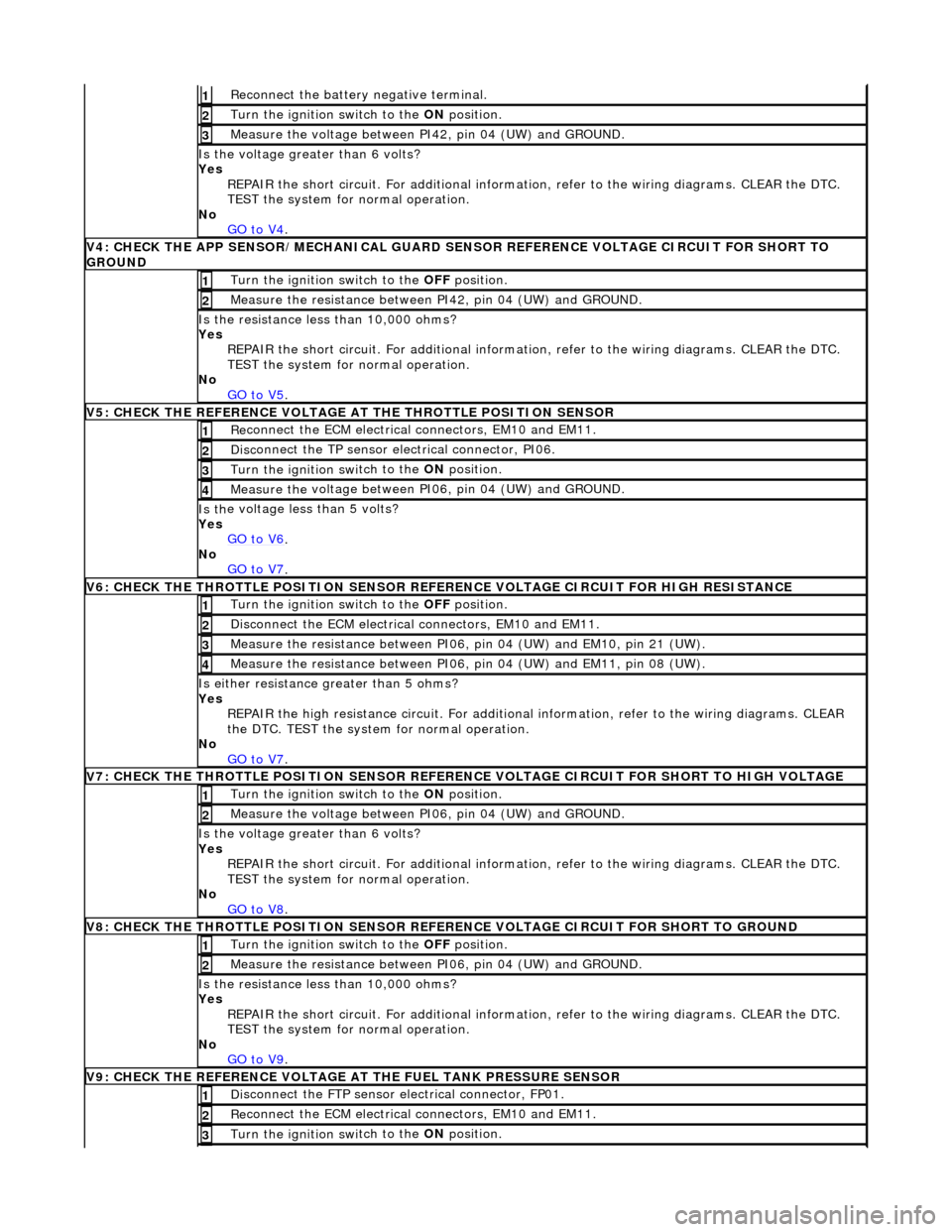
R
econnect the battery negative terminal.
1
Turn the ignition swi
tch to the ON
position.
2
Measure the
voltage between PI
42, pin 04 (UW) and GROUND.
3
Is th
e voltage greater than 6 volts?
Yes REPAIR the short circuit. For addi tional information, refer to the wiring diagrams. CLEAR the DTC.
TEST the system for normal operation.
No GO to V4
.
V
4: CHECK THE APP SENSOR/MECHA
NICAL GUARD SENSOR REFERENCE VOLTAGE CIRCUIT FOR SHORT TO
GROUND
Turn the ignition swi
tch to the
OFF position.
1
Meas
ure the resistance between PI42, pin 04 (UW) and GROUND.
2
Is
the resistance less than 10,000 ohms?
Yes REPAIR the short circuit. For addi tional information, refer to the wiring diagrams. CLEAR the DTC.
TEST the system for normal operation.
No GO to V5
.
V
5: CHECK THE REFERENCE VOLTAGE AT THE THROTTLE POSITION SENSOR
Re
connect the ECM electrical connectors, EM10 and EM11.
1
Disc
onnect the TP sensor electrical connector, PI06.
2
Turn the ignition swi
tch to the ON
position.
3
Measure the
voltage between PI
06, pin 04 (UW) and GROUND.
4
Is th
e voltage less than 5 volts?
Yes GO to V6
.
No
GO to V7
.
V
6: CHECK THE THROTTLE POSITION SENSOR REFE
RENCE VOLTAGE CIRCUIT FOR HIGH RESISTANCE
Turn the ignition swi
tch to the OFF
position.
1
D
isconnect the ECM electrical connectors, EM10 and EM11.
2
Me
asure the resistance between PI06, pin 04 (UW) and EM10, pin 21 (UW).
3
Me
asure the resistance between PI06, pin 04 (UW) and EM11, pin 08 (UW).
4
Is either resi
stance
greater than 5 ohms?
Yes REPAIR the high resistance circui t. For additional information, refer to the wiring diagrams. CLEAR
the DTC. TEST the system for normal operation.
No GO to V7
.
V
7: CHECK THE THROTTLE POSITION SENSOR REFERENCE VOLTAGE CIRCUIT FOR SHORT TO HIGH VOLTAGE
Turn the ignition swi
tch to the ON
position.
1
Measure the
voltage between PI
06, pin 04 (UW) and GROUND.
2
Is th
e voltage greater than 6 volts?
Yes REPAIR the short circuit. For addi tional information, refer to the wiring diagrams. CLEAR the DTC.
TEST the system for normal operation.
No
GO to V8
.
V
8: CHECK THE THROTTLE POSITION SENSOR REFE
RENCE VOLTAGE CIRCUIT FOR SHORT TO GROUND
Turn the ignition swi
tch to the OFF
position.
1
Meas
ure the resistance between PI06, pin 04 (UW) and GROUND.
2
Is
the resistance less than 10,000 ohms?
Yes REPAIR the short circuit. For addi tional information, refer to the wiring diagrams. CLEAR the DTC.
TEST the system for normal operation.
No GO to V9
.
V
9: CHECK THE REFERENCE VOLTAGE AT THE FUEL TANK PRESSURE SENSOR
Di
sconnect the FTP sensor electrical connector, FP01.
1
Re
connect the ECM electrical connectors, EM10 and EM11.
2
Turn the ignition swi
tch to the ON
position.
3
Page 1226 of 2490
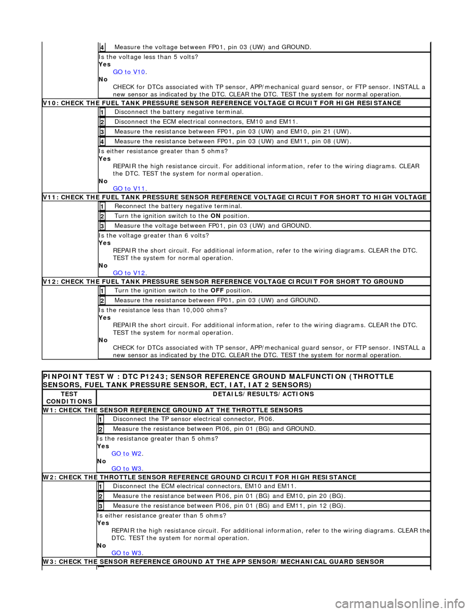
Measure the voltage between FP 01
, pin 03 (UW) and GROUND.
4
Is th
e volt
age less than 5 volts?
Yes GO to V10
.
No
CHECK
for DTCs associated with
TP sensor, APP/mechanical guard sensor, or FTP sensor. INSTALL a
new sensor as indicated by the DTC. CLEAR the DTC. TEST the system for normal operation.
V
10: CHECK
THE FUEL TANK PRESSURE SENSOR
REFERENCE VOLTAGE CIRCUIT FOR HIGH RESISTANCE
Disc
onnect the battery negative terminal.
1
D
i
sconnect the ECM electrical connectors, EM10 and EM11.
2
Measure t
he resistance between FP01,
pin 03 (UW) and EM10, pin 21 (UW).
3
Measure t
he resistance between FP01,
pin 03 (UW) and EM11, pin 08 (UW).
4
Is either resistance greater
than 5 ohms?
Yes REPAIR the high resistance circui t. For additional information, refer to the wiring diagrams. CLEAR
the DTC. TEST the system for normal operation.
No GO to V11
.
V11: CHECK
THE FUEL TANK PRESSURE SENSOR REFE
RENCE VOLTAGE CIRCUIT FOR SHORT TO HIGH VOLTAGE
Re
connect the battery negative terminal.
1
Turn the ignition swi
t
ch to the ON
position.
2
Measure the voltage between FP 01
, pin 03 (UW) and GROUND.
3
Is th
e volt
age greater than 6 volts?
Yes REPAIR the short circuit. For addi tional information, refer to the wiring diagrams. CLEAR the DTC.
TEST the system for normal operation.
No GO to V12
.
V12: CHECK
THE FUEL TANK PRESSURE SENSOR
REFERENCE VOLTAGE CIRCUIT FOR SHORT TO GROUND
Turn the ignition swit
ch to the OFF
position.
1
Measure t
he resistance between
FP01, pin 03 (UW) and GROUND.
2
Is t
he resistance less than 10,000 ohms?
Yes REPAIR the short circuit. For addi tional information, refer to the wiring diagrams. CLEAR the DTC.
TEST the system for normal operation.
No CHECK for DTCs associated with TP sensor, APP/mechanical guard sensor, or FTP sensor. INSTALL a
new sensor as indicated by the DTC. CLEAR the DTC. TEST the system for normal operation.
PI
NPOINT TEST W : DTC P1243; SENSOR RE
FERENCE GROUND MALFUNCTION (THROTTLE
SENSORS, FUEL TANK PRESSURE SENSOR, ECT, IAT, IAT 2 SENSORS)
TE S
T
CONDITIONS
D E
TAILS/RESULTS/ACTIONS
W1: CHECK THE SENSO
R
REFERENCE
GROUND AT THE THROTTLE SENSORS
Disc
onne
ct the TP sensor electrical connector, PI06.
1
Meas
ure t
he resistance between PI06, pin 01 (BG) and GROUND.
2
Is th
e res
istance greater than 5 ohms?
Yes GO to W2
.
No
GO to W3
.
W2: CHECK TH
E THROTTLE SENSOR REFERENCE GROUND CIRCUIT FOR HIGH RESISTANCE
D
i
sconnect the ECM electrical connectors, EM10 and EM11.
1
Meas
ure t
he resistance between PI06,
pin 01 (BG) and EM10, pin 20 (BG).
2
Measure t
he resistance between PI06,
pin 01 (BG) and EM11, pin 12 (BG).
3
Is either resistance greater
than 5 ohms?
Yes REPAIR the high resistance circuit. For additional information, refer to the wiring diagrams. CLEAR the
DTC. TEST the system for normal operation.
No GO to W3
.
W3: CHECK THE SENSO R
REFERENCE GROUND AT
THE APP SENSOR/MECHANICAL GUARD SENSOR
Page 1227 of 2490

Di
sconnect the APP sensor/mechanical guard sensor electrical connector, PI42.
1
Re
connect the ECM electrical connectors, EM10 and EM11.
2
Meas
ure the resistance between PI42, pin 02 (BG) and GROUND.
3
Is th
e resistance greater than 5 ohms?
Yes GO to W4
.
No
GO to W5
.
W4: CHECK THE APP
SENSOR/MECHANICAL GUARD SE
NSOR REFERENCE GROUND CIRCUIT FOR HIGH
RESISTANCE
D
isconnect the ECM electrical connectors, EM10 and EM11.
1
Meas
ure the resistance between PI42,
pin 02 (BG) and EM10, pin 20 (BG).
2
Meas
ure the resistance between PI42,
pin 02 (BG) and EM11, pin 12 (BG).
3
Is either resi
stance
greater than 5 ohms?
Yes REPAIR the high resistance circuit. For additional information, refer to the wiring diagrams. CLEAR the
DTC. TEST the system for normal operation.
No GO to W5
.
W5: CHECK THE SENSO
R REFERENCE GROUND AT THE FUEL TANK PRESSURE SENSOR
Di
sconnect the FTP sensor electrical connector, FP01.
1
Re
connect the ECM electrical connectors, EM10 and EM11.
2
Meas
ure the resistance between
FP01, pin 01 (BG) and GROUND.
3
Is th
e resistance greater than 5 ohms?
Yes GO to W6
.
No
GO to W7
.
W6: CHECK THE FUEL
TANK PRESSURE SENSOR RE
FERENCE GROUND CIRCUIT FOR HIGH RESISTANCE
D
isconnect the ECM electrical connectors, EM10 and EM11.
1
Meas
ure the resistance between FP01,
pin 01 (BG) and EM10, pin 20 (BG).
2
Meas
ure the resistance between FP01,
pin 01 (BG) and EM11, pin 12 (BG).
3
Is either resi
stance
greater than 5 ohms?
Yes REPAIR the high resistance circuit. For additional information, refer to the wiring diagrams. CLEAR the
DTC. TEST the system for normal operation.
No GO to W7
.
W7: CHECK THE SENSO
R REFERENCE GROUND AT THE ECT SENSOR
Re
connect the ECM electrical connectors, EM10 and EM11.
1
D
isconnect the ECT sensor electrical connector, PI04.
2
Meas
ure the resistance between PI04, pin 01 (BG) and GROUND.
3
Is th
e resistance greater than 5 ohms?
Yes GO to W8
.
No
GO to W9
.
W8: CHECK THE ECT SEN
SOR REFERENCE
GROUND CIRCUIT FOR HIGH RESISTANCE
D
isconnect the ECM electrical connectors, EM10 and EM11.
1
Meas
ure the resistance between PI04,
pin 01 (BG) and EM10, pin 20 (BG).
2
Meas
ure the resistance between PI04,
pin 01 (BG) and EM11, pin 12 (BG).
3
Is either resi
stance
greater than 5 ohms?
Yes REPAIR the high resistance circuit. For additional information, refer to the wiring diagrams. CLEAR the
DTC. TEST the system for normal operation.
No GO to W9
.
W9: CHECK THE SENSO
R REFERENCE GR
OUND AT THE IAT SENSOR (MAF)
Re
connect the ECM electrical connectors, EM10 and EM11.
1
Di
sconnect the IAT sensor (MAF) electrical connector, PI35.
2
Meas
ure the resistance between PI35, pin 04 (BG) and GROUND.
3
Page 1530 of 2490
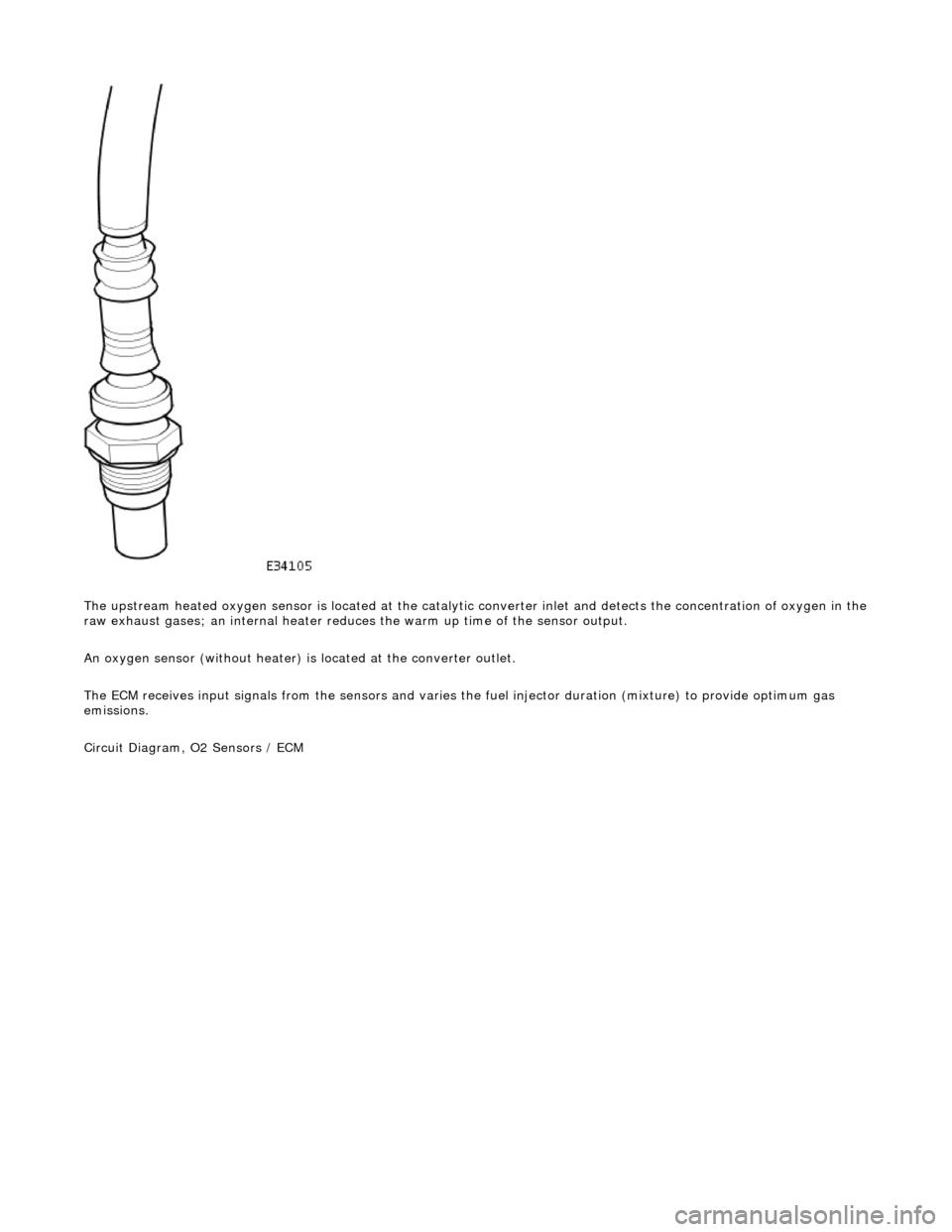
The upstream heated oxygen sensor is located at the catalytic converter inlet and detects the concentration of oxygen in the
raw exhaust gases; an internal heater reduces the warm up time of the sensor output.
An oxygen sensor (without heater) is located at the converter outlet.
The ECM receives input signals from the se nsors and varies the fuel injector duration (mixture) to provide optimum gas
emissions.
Circuit Diagram, O2 Sensors / ECM
Page 1696 of 2490
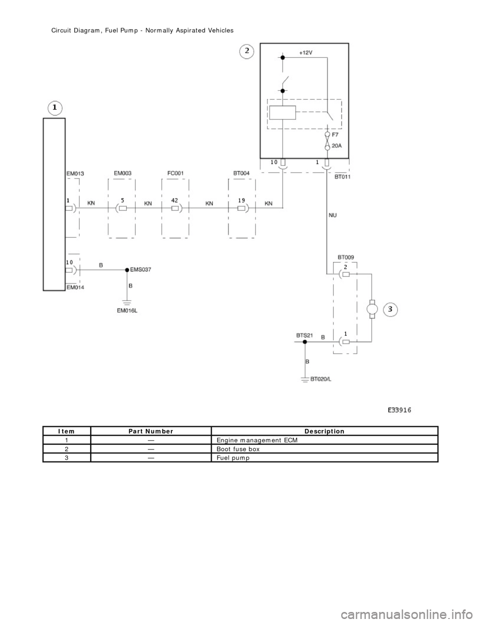
Ite
m
Par
t
Number
De
scr
iption
1—Engine
m
anagement ECM
2—Boot fuse box
3—Fue
l
pump
Ci
rcui
t Diagram, Fuel Pump -
Normally Aspirated Vehicles
Page 1697 of 2490
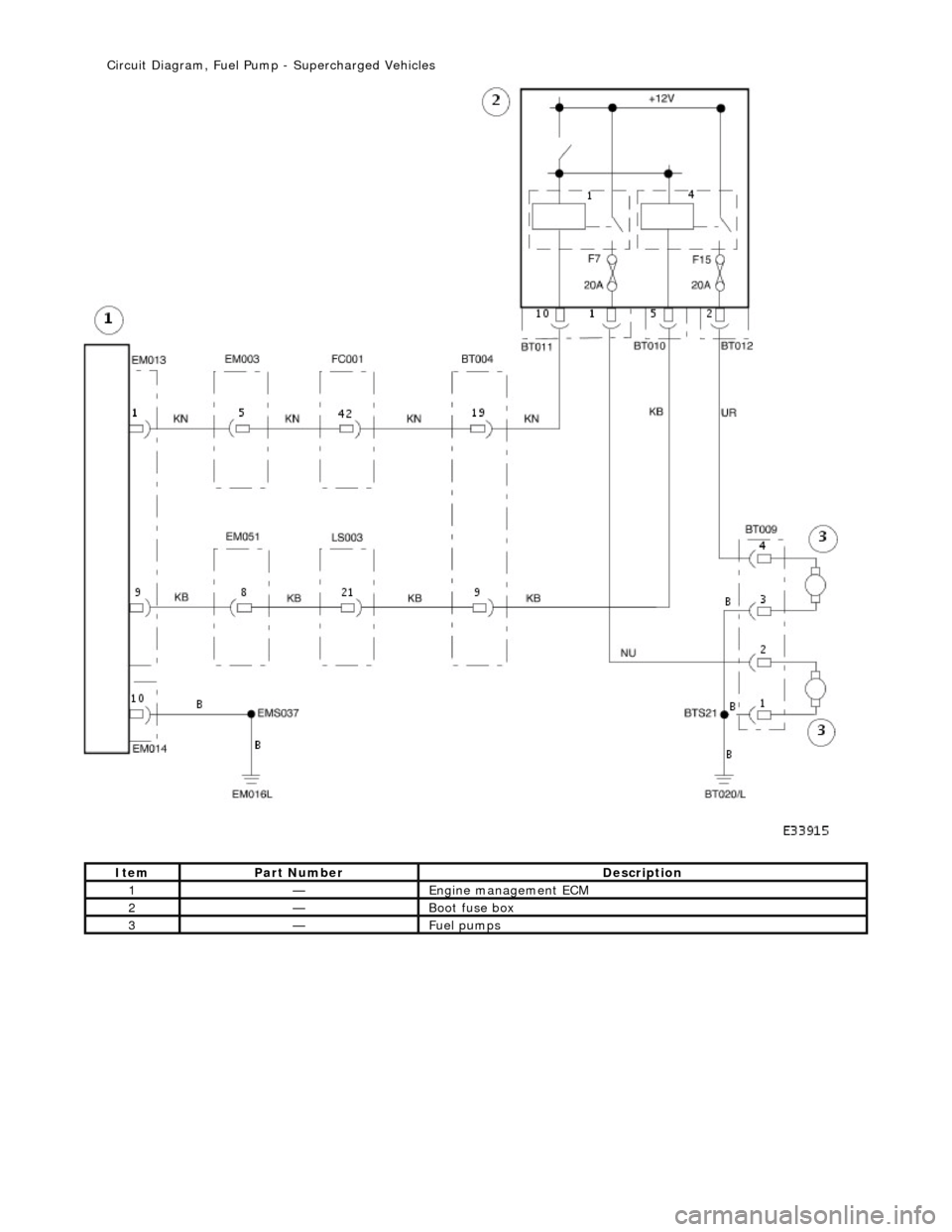
It
em
Par
t Number
De
scription
1—Engine
management ECM
2—Boot fuse box
3—Fue
l pumps
Ci
rcuit Diagram, Fuel Pump
- Supercharged Vehicles