torque JAGUAR X308 1998 2.G Workshop Manual
[x] Cancel search | Manufacturer: JAGUAR, Model Year: 1998, Model line: X308, Model: JAGUAR X308 1998 2.GPages: 2490, PDF Size: 69.81 MB
Page 16 of 2490

В В В В В В В В В В В В В В В В В В В В KnockВ Sensor В (KS) В RH В (18.30.93) В
В В В В В В В В В В В В В В В В В В В В
VariableВ Camshaft В Timing В (VCT) В Oil В Co ntrol
В
Solenoid В (18.30.90) В
В
В В В В В В В В
307: В Automatic В Transmission/Transaxle В
В
В В В В В В В В В В В В 307‐01A :В Automatic В Transmission/Transaxle  ‐ 3.2L В NA В V8  ‐ AJ26/4.0LВ NAВ V8  ‐ AJ27 В
В В В В В В В В В В В В В В В В Specification В
В В В В В В В В В В В В В В В В Description В and В Operation В
В В В В В В В В В В В В В В В В В В В В TransmissionВ DescriptionВ
В В В В В В В В В В В В В В В В Diagnosis В and В Testing В
В В В В В В В В В В В В В В В В В В В В DiagnosticВ Strategy В
В В В В В В В В В В В В В В В В GeneralВ Procedures В
В В В В В В В В В В В В В В В В В В В В TransmissionВ FluidВ Drain В and В Refill В (44.24.02) В
                In‐Ve
hicle В Repair В
В В В В В В В В В В В В В В В В В В В В ElectronicВ PressureВ ControlВ (EPC)В Solenoid В (44.15.51) В
В В В В В В В В В В В В В В В В В В В В ExtensionВ Housing В Seal В (44.20.18) В
В В В В В В В В В В В В В В В В В В В В ExtensionВ Housing В O ‐Ring В Seal В (44.20.19) В
В В В В В В В В В В В В В В В В В В В В MainВ ControlВ ValveВ BodyВ (44.40.01) В
В В В В В В В В В В В В В В В В В В В В OutputВ Shaft В Speed В (OSS) В Sensor В (44.15.41) В
В В В В В В В В В В В В В В В В В В В В ShiftВ Solenoids В (SS) В (44.15.50) В
В В В В В В В В В В В В В В В В В В В В TransmissionВ ControlВ Module В (TCM) В (44.15.32) В
В В В В В В В В В В В В В В В В В В В В TransmissionВ FluidВ Filter В (44.24.07) В
В В В В В В В В В В В В В В В В В В В В TransmissionВ Fl
uid В Pan В (44.24.04) В
В В В В В В В В В В В В В В В В В В В В TransmissionВ FluidВ Pan В Gasket В (44.24.05) В
В В В В В В В В В В В В В В В В В В В В TransmissionВ InternalВ Wiring В Harness В (44.15.35) В
В В В В В В В В В В В В В В В В В В В В TransmissionВ InternalВ Wiring В Harness В Electrical В ConnectorВ O‐Ring В SealsВ В
В В В В В В В В В В (44.24.20)В
В В В В В В В В В В В В В В В В В В В В TransmissionВ RangeВ (TR)В Sensor В
В В В В В В В В В В В В В В В В В В В В TransmissionВ SupportВ InsulatorВ (12.45.04) В
В В В В В В В В В В В В В В В В В В В В TurbineВ Shaft В Speed В (TSS) В Sensor В (44.15.40) В
В В В В В В В В В В В В В В В В RemovalВ
В В В В В В В В В В В В В В В В В В В В TransmissionВ (44.20.01)В
В В В В В В В В В В В В В В В В Disassembly В and В AssemblyВ ofВ Subassemblies В
В В В В В В В В В В В В В В В В В В В В InputВ Sh
aft В Seal В (44.32.07) В
В В В В В В В В В В В В В В В В В В В В TorqueВ Converter В (44.17.07) В
В В В В В В В В В В В В В В В В Installation В
В В В В В В В В В В В В В В В В В В В В TransmissionВ (44.20.01)В
Mass
В
Airflow
В
Sen s
or
В
Knock
В Sensor
В (KS)
В LH
В (18.30.92)
В
Page 17 of 2490

В
            307‐01B : A u
tomatic
В Transmission/Transaxle  ‐ 4.0L В SCВ V8 ‐ AJ26 В
В В В В В В В В В В В В В В В В Specification В
В В В В В В В В В В В В В В В В Description В and В Operation В
В В В В В В В В В В В В В В В В В В В В TransmissionВ DescriptionВ
В В В В В В В В В В В В В В В В Diagnosis В and В Testing В
В В В В В В В В В В В В В В В В В В В В DiagnosticВ Strategy В
В В В В В В В В В В В В В В В В GeneralВ Procedures В
В В В В В В В В В В В В В В В В В В В В TransmissionВ FluidВ Drain В and В Refill В (44.24.02) В
В В В В В В В В В В В В В В В В In‐Vehicle В Repair В
В В В В В В В В В В В В В В В В В В В В ExtensionВ Housing В Seal В (44.20.18) В
В В В В В В В В В В В В В В В В В В В В MainВ ControlВ ValveВ BodyВ (44.40.01) В
В В В В В В В В В В В В В В В В В В В В TransmissionВ FluidВ Filter В (44.24.07) В
В В В В В В В В В В В В В В В В В В В В TransmissionВ Fl
uid В Pan В Gasket В (44.24.05) В
В В В В В В В В В В В В В В В В В В В В TransmissionВ InternalВ Wiring В Harness В Electrical В ConnectorВ O‐Ring В SealsВ В
В В В В В В В В В В (44.24.20)В
В В В В В В В В В В В В В В В В В В В В TransmissionВ SupportВ InsulatorВ (12.45.04) В
В В В В В В В В В В В В В В В В RemovalВ
В В В В В В В В В В В В В В В В В В В В TransmissionВ (44.20.01)В
В В В В В В В В В В В В В В В В Disassembly В and В AssemblyВ ofВ Subassemblies В
В В В В В В В В В В В В В В В В В В В В InputВ Shaft В Seal В (44.32.07) В
В В В В В В В В В В В В В В В В В В В В TorqueВ Converter В (44.17.07) В
В В В В В В В В В В В В В В В В Installation В
В В В В В В В В В В В В В В В В В В В В TransmissionВ (44.20.01)В
В
            307‐02A : Transmission/Transaxle  Cooling  ‐ 3.2L  NA  V8  ‐ AJ26/4.0L  NA  V8  ‐ AJ
27 В
В В В В В В В В В В В В В В В В Description В and В Operation В
В В В В В В В В В В В В В В В В В В В В TransmissionВ CoolingВ
В
В В В В В В В В В В В В 307‐02B :В Transmission/Transaxle В Cooling  ‐ 4.0L В SCВ V8 ‐ AJ26 В
В В В В В В В В В В В В В В В В Description В and В Operation В
В В В В В В В В В В В В В В В В В В В В TransmissionВ CoolingВ
В
В В В В В В В В В В В В 307‐05A :В Automatic В Transmission/Transaxle В External В Controls  ‐ 3.2L В NA В V8  – В
В В В В В В В В В В AJ26/4.0LВ NA В V8  ‐ AJ27 В
В В В В В В В В В В В В В В В В Description В and В Operation В
В В В В В В В В В В В В В В В В В В В В ExternalВ Controls В
Page 36 of 2490
пЃ¬Gener
al specifications (including setting-up information, capacities, lubricants, fluids, sealants and adhesives).
пЃ¬To
r
que specifications.
Description and Operation
пЃ¬A g
eneral illustration and part
s list to identify the components which comp rise a particular system or assembly.
пЃ¬A b
rief description of the system operating characteristics or description of the assembly.
пЃ¬A d
escription of each component and its function.
Diagnosis and Testing
пЃ¬D e
scriptions of how to iden
tify system problems.
пЃ¬Inspection and verifi
cation information.
пЃ¬S
y
mptom charts comprising fault conditions, possible sources and actions.
General Procedures
пЃ¬G e
neral maintenance procedures, including adjustment, alig
nment, bleeding and filling, with illustrated steps and
supporting text.
пЃ¬Tigh te
ning torque specifications, shown in the illustrations.
Removal and Installation
пЃ¬Com p
onent removal and installation maintenance proced
ures, with illustrated steps and supporting text.
пЃ¬Tighte
ning torque specifications, shown in the illustrations.
пЃ¬An i
llustrated tool
chart for each proced
ure requiring the use of special tools.
Disassembly and Assembly
пЃ¬Compon ent disassembly and
assembly
maintenance procedures, with illust rated steps and supporting text.
пЃ¬Tighte
ning torque specifications, shown in the illustrations.
пЃ¬An i
llustrated tool
chart for each proced
ure requiring the use of special tools.
Repairs and Replacem
ents
Wh
en s
ervice parts are required, it is essential that only genuine Jaguar/Daimler replacements are used.
Attention is drawn to the following points concerning repa irs and the fitting of replacement parts and accessories:
пЃ¬Safety feat
ures embodied in the vehicle
may be impaired if other than genuine parts are fitted. In certain territories,
legislation prohibits the fitting of pa rts which are not produced to the vehi cle manufacturer's specification.
пЃ¬Torque wrench setting figures given i
n this manual must be strictly adhered to. Locking devices, where specified,
must be fitted. If the efficiency of a locking device is impaired during removal it must be renewed.
пЃ¬O w
ners purchasing accessories
while travelling abroad should ensure that the accessory and its fitted location on the
vehicle conform to mandatory requirements existing in their country of origin.
пЃ¬The vehicle warranty may be invali
dated by the fitting
of other than genuine Ja guar/Daimler parts. All
Jaguar/Daimler replacements have the fu ll backing of the factory warranty.
пЃ¬Jaguar/Daimler dealers are obliged to
supply only genuine service parts.
Thread Locking Devices
P a
tched Fasteners
Two types
of
patched fastener are essentially used on certai
n suspension, steering and other critical components, where
operational movement of the component necessitates positive thread locking. Standard patched fasteners have part
numbers bearing the suffix le tter M. For identification of special patched fa steners, refer to the list of patched fasteners
below, or the relevant component drawings.
Jaguar Specification JFS 02.01.02 patched fasteners incorporate a micro-encapsulated adhesive which is released into the
mating threads during tightening. Following final tightening, the adhesive in this type of patched fastener must be allowed a
period to cure before the component/vehicle is used. On removal, this type of fastener must be discarded and a new
Page 37 of 2490
patc
hed fastener of the same specification fitted. All mating th
reads must be thoroughly cleaned prior to fitting of the new
fastener.
Jaguar Specification JFS 02.01.04 patched fasteners incorporat e a plastic/polyester on the thread. Acting as a wedge
between the mating threads, this compound imposes a prevaili ng torque during tightening. Whilst this type of patched
fastener can be re-used, the imposed torq ue diminishes. It is therefore recommended that following third removal, this type
of patched fastener is discarded and a new fast ener of the same specification is fitted.
Special fasteners bearing the following pa rt numbers are of the micro-encapsulated adhesive type and following removal,
must be discarded and replaced by ne w items of the same specification:
CAC 8223
JZB 10060; JZB 10061; JZB 10078.
JZH 100027.
JZS 100082; JZS100087; JZS 100088; JZS 100089; JZS 100090; JZS 100118; JZS 100157; JZS 100164; JZS 100166.
NCA 1451 AA.
Vehicle Specifications
Purchasers are advised th
at th
e specification details set out in this manual apply to a range of vehicles and not to any
specific one. For the specificatio n of a particular vehicle, purchasers should consult their dealer.
The Manufacturer reserves the right to vary the specifications, with or without notice, and at such times and in such manner
as the Manufacturer thinks fit. Major as well as minor changes may be involved , in accordance with the Manufacturer's
policy of continuous improvement.
Whilst every effort is made to ensure the accuracy of the pa rticulars contained in this manual, neither the Manufacturer nor
the Dealer, by whom the manual is supplied, shall in any circumstances be held liable for any inaccuracy or the
consequences thereof.
Serv
ice Repair Operation Numbering
A
master index of numbered operations has been compiled for
universal application to all vehicles manufactured by Jaguar
Cars Ltd.
Each operation is allocated a number from the master index and cross-refers with an identical number in the Repair
Operation Times schedule. The number consists of six digits arranged in three pairs.
Each maintenance procedure in this manual is described in the sequence necessary to complete the operation in the
minimum time, as specified in the Repair Operation Times schedule for this range of vehicles.
Re
ferences to Left- and Right-Hand
R
eferences to the left- or
right-hand side of the vehicle are made as if viewing from the driver's seat.
Ref
erences to Engine Banks
Wi
th the engine installed in the vehicle, the right-hand cylinder
bank is designated Bank A, and the left-hand cylinder bank
is designated Bank B.
Specia
l Tools
Any special too
ls and equipment required
to perform a maintenance procedure, are shown at the beginning of each
maintenance procedure.
Page 38 of 2490
Torque Specifications
Torque sp
ecifications are shown in maintenance procedure illustra
tions and also in the torque specifications chart located at
the front of the relevant section.
Disconnecting/Connecting the Battery
Ow ing t
o the electronic components used on the vehicle, it is important that the battery is disconnected when specified in a
maintenance procedure.
When the battery is connected, the specified procedure must be followed, to ensure the correct operation of all vehicle
systems; refer to Section 414-01.
Use of Control Modules
Control modu les may
only be used on the ve
hicle to which they were originally fitted. Do not attempt to use or test a control
module on any other vehicle.
Function
al Test
On
completion of a maintenance procedure, a thorough test should be carried out, to ensu
re that the relevant vehicle
systems are working correctly.
Protecting the Vehicle
Al ways
fit covers to protect
the fenders before commencing work in the engi ne compartment. Cover the seats and carpets,
wear clean overalls and wash hands or wear gloves before working inside the vehicle. Avoid spilling hydraulic fluid,
antifreeze or battery acid on the paintwork. In the event of spillage, wash off with water imme diately. Use polythene sheets
in the trunk to protect carpets. Always use the recommended service tool, or a satisfactory equivalent, where specified.
Protect temporarily exposed screw thread s by replacing nuts or fitting caps.
Preparation
Before disassembly, clean the surrounding ar ea
as thoroughly as possible. When co
mponents have been removed, blank off
any exposed openings using grease-proof paper and masking tape. Immediately seal fuel, oil and hydraulic lines when
separated, using plastic caps or plugs, to prevent loss of fluid and the entry of dirt. Close the open ends of oilways, exposed
by component removal, with tapered hardw ood plugs or readily visible plastic plugs. Immediately a component is removed,
place it in a suitable container; use a se parate container for each component and its associated pa rts. Before dismantling a
component, clean it thoroughly with a recommended cleaning agent; check that the agent will not damage any of the
materials within the component. Clean the bench and obtain ma rking materials, labels, containers and locking wire before
dismantling a component.
Dismantling
O b
serve scrupulous cleanliness when dismantling components,
particularly when parts of the brake, fuel or hydraulic
systems are being worked on. A particle of dirt or a fragment of cloth could caus e a dangerous malfunction if trapped in
these systems. Clean all tapped holes, crev ices, oilways and fluid passages with compressed air. Do not permit compressed
air to enter an open wound. Always use ey e protection when using compressed air.
Ensure that any O-rings used for sealing are correctly refitted or renewed if disturbed. Mark mating parts to ensure that
they are replaced as dismantled. Whenever possible use markin g materials which avoid the possibilities of causing distortion
or the initiation of cracks, which could occur if a center pu nch or scriber were used. Wire together mating parts where
necessary to prevent accidental interchange (e.g roller bearing components). Tie labels on to all parts to be renewed and to
parts requiring further inspection before being passed fo r reassembly. Place labelled parts and other parts for rebuild in
separate containers. Do not disc ard a part which is due for renewal until it ha s been compared with the new part, to ensure
that the correct part has been obtained.
Page 41 of 2490
•
NOTE: For convenience, pinpoint test il
lustrations indicating voltage measurements do not always accurately reflect the
conventional method of connecting a multimeter. More explicitly, if the multimeter probes are connected as shown in some
illustrations (positive probe to ground), the voltage reading would be preceded by the negative sign '-', indicating that the
probes have been connected in the reverse manner to the norm al convention. The accuracy of the reading is not affected
and the '-' sign can be ignored when comparing the reading with the results indicated in the text of the pinpoint test.
Removal and Installation
пЃ¬Re
moval procedure(s), formatted
in the recommended sequence
пЃ¬Il
lustrated guide to the use of special tools
пЃ¬Il
lustrations to support the relevant text
пЃ¬Installation
procedure as above and including special re
commendations for processes, lubricants and tightening
torques.
Cir
cuit Diagrams
To
understand the relationship between the vehicle electric
al system and the system circuit diagrams, refer to the
appropriate Electrical Guide.
Fault Identificatio
n (DTC)
The diagnostic trouble codes (DTCs) are
li
sted in Section 303-00 under Diagno
stic Trouble Codes and include, where
applicable, the corresponding manual section reference.
Page 42 of 2490
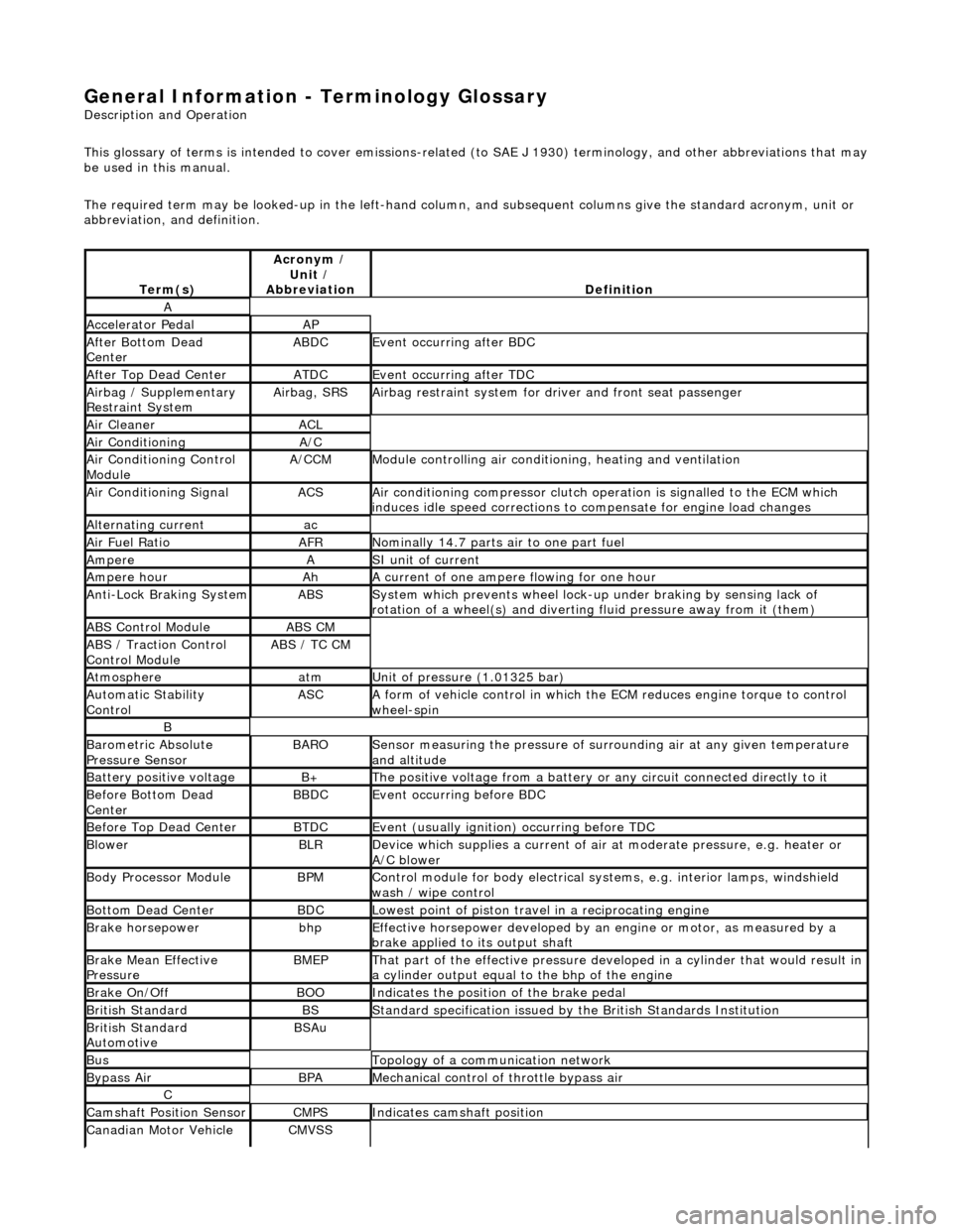
General Information - Terminology Glossary
Description an
d Operation
This glossary of terms is intended to cover emissions-related (to SAE J 1930) term inology, and other abbreviations that may
be used in this manual.
The required term may be looked-up in th e left-hand column, and subsequent columns give the standard acronym, unit or
abbreviation, and definition.
Te rm
(s)
Acr
ony
m /
Unit /
Abbreviation
De fi
nition
A
Accel
e
rator Pedal
AP
Af
ter Botto
m Dead
Center
ABDCEvent occurri ng after
BDC
Af
ter Top Dead CenterATDCEvent occurri ng after
TDC
Ai
rbag /
Supplementary
Restraint System
Airbag, SRSAi rbag restraint system for
dr
iver and front seat passenger
Air Cleane rACL
Air ConditioningA/C
Air Conditioning Con t
rol
Module
A/CCMModule c
ontrolling air conditioning, heating and ventilation
Air Conditioning SignalACSA
i
r conditioning compressor clutch operation is signalled to the ECM which
induces idle speed corrections to co mpensate for engine load changes
Alternating cu
rrent
ac
Ai
r Fuel R
atio
AFRN
omi
nally 14.7 parts air to one part fuel
Ampe
reASI unit of current
Ampere hourAhA current of one ampere
fl
owing for one hour
Anti-Lock Braking SystemABSS
y
stem which prevents wheel lock-up
under braking by sensing lack of
rotation of a wheel(s) and divertin g fluid pressure away from it (them)
ABS Control Mo
dule
ABS CM
ABS /
T
raction Control
Control Module
ABS / T
C CM
Atmosph
e
re
atmU
n
it of pressure (1.01325 bar)
Au
to
matic Stability
Control
ASCA form of vehicle
control
in which the ECM reduces en gine torque to control
wheel-spin
B
Baro me
tric Absolute
Pressure Sensor
BAR OSensor measuring the pressure of surr ou
nding air at any given temperature
and altitude
Bat t
ery positive voltage
B+The posi
ti
ve voltage from a battery or
any circuit connected directly to it
Before Bottom Dead
CenterBBDCEvent occurri ng before BD
C
Before Top Dead
Center
BTD
CEvent (usual ly
ignition) occurring before TDC
Blowe
rBLRDe
vice which supplies a current of air at
moderate pressure, e.g. heater or
A/C blower
Body Processor M
odule
BPMControl modu
le
for body electrical systems, e.g. interior lamps, windshield
wash / wipe control
Bott om D
ead Center
BD
CLowest poin t of piston
travel in a reciprocating engine
Brake hors
epowe
r
bhpEffecti
ve horsepower devel
oped by an
engine or motor, as measured by a
brake applied to its output shaft
Brake Mean Effective
Pres sureBME PThat p
art of the effective
pressure developed in a cyli nder that would result in
a cylinder output equal to the bhp of the engine
Brake On/ O
ff
BOOIn
dic
ates the position of the brake pedal
Br
it
ish Standard
BSStan
dar
d specification issued by the British Standards Institution
Br
it
ish Standard
Automotive
BSAu
BusTopology of a commu n
ication network
Bypass
AirBPAMechanica l
control of throttle bypass air
C
Camshaft Posit
i
on Sensor
CMPSIndi
cat
es camshaft position
Canadian Motor
V
ehicle
CMVSS
Page 46 of 2490
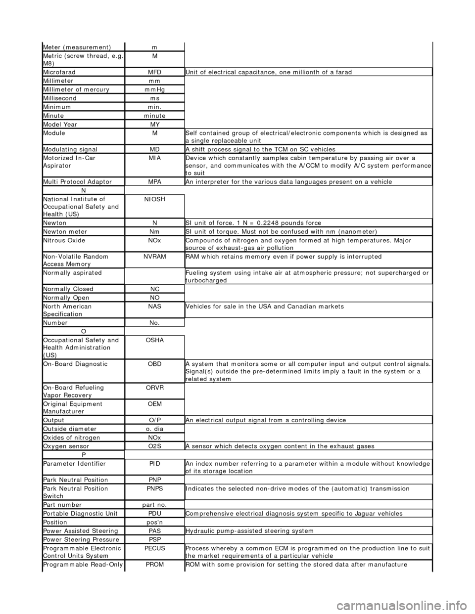
Meter (measurement)m
Me
tric (screw thread, e.g.
M8)
M
MicrofaradMFDUni t
of electrical capacitance, one millionth of a farad
Mi
ll
imeter
mm
Mi
ll
imeter of mercury
mm
Hg
Mill
isecond
ms
Min
i
mum
mi
n.
Min u
te
minut
e
Model YearMY
ModuleMSelf
contained group of electrical/electronic components which is designed as
a single replaceable unit
Modulating signalMDA sh
ift process signal to the TCM on SC vehicles
Motorized In
-Car
AspiratorMIAD e
vice which constantly samples cabi
n temperature by passing air over a
sensor, and communicates with the A/ CCM to modify A/C system performance
to suit
Mult i Prot
ocol Adaptor
MPAAn i
n
terpreter for the various data
languages present on a vehicle
N
Nati
onal Institute of
Occupational Safety and
Health (US)
NIO S
H
Ne
wto
n
NSI unit of force. 1
N = 0.224
8 pounds force
Ne
wto
n meter
NmSI unit of torque. Must not be
co
nfused with nm (nanometer)
Ni
tr
ous Oxide
NO
xCompounds of nit rogen and oxygen fo rmed at high temperatures. Major
sourc
e of exhaust-gas air pollution
No
n
-Volatile Random
Access Memory
NVR A
M
R
A
M which retains memory even
if power supply is interrupted
Normal
ly aspirated
F
u
eling system using intake air at atmo
spheric pressure; not supercharged or
turbocharged
N ormal
ly Closed
NC
N
o
rmally Open
NO
No
r
th American
Specification
NASVehicles f or sal
e in the USA and Canadian markets
Nu
mbe
r
No
.
O
Oc
cupational Safety and
Health Administration
(US)
OS H
A
O
n
-Board Diagnostic
OB
DA system that moni
tors some or all co
mputer input and output control signals.
Signal(s) outside the pre-de termined limits imply a fault in the system or a
related system
O n
-Board Refueling
Vapor Recovery
OR V
R
O
riginal
Equipment
Manufacturer
OE M
Outp
ut
O/
PAn electrical o u
tput signal from a controlling device
Ou
ts
ide diameter
o.
d
ia
O
xides of
nitrogen
NO
x
Oxygen senso
r
O2
SA s
ensor which detects oxygen content in the exhaust gases
P
Parameter Identifi
erPIDAn in
dex number referring to a parame
ter within a module without knowledge
of its storage location
Park N e
utral Position
PN
P
Park N e
utral Position
Switch
PN PSIndic
ates the selected non-drive modes of the (automatic) transmission
Part numberpart no.
Portable Diag
nostic Un
it
PD
UCompre hen
sive electrical diagnosis system specific to Jaguar vehicles
Posi
ti
on
po
s'n
Power As si
sted Steering
PASHydraul
i
c pump-assisted steering system
Power Steer
i
ng Pressure
PSP
Programmable Elect
r
onic
Control Units System
PECU SProcess whereb y
a common ECM is progra
mmed on the production line to suit
the market requirements of a particular vehicle
Programmable Read-O
nly
PROMRO
M with some provision for setting
the stored data after manufacture
Page 48 of 2490
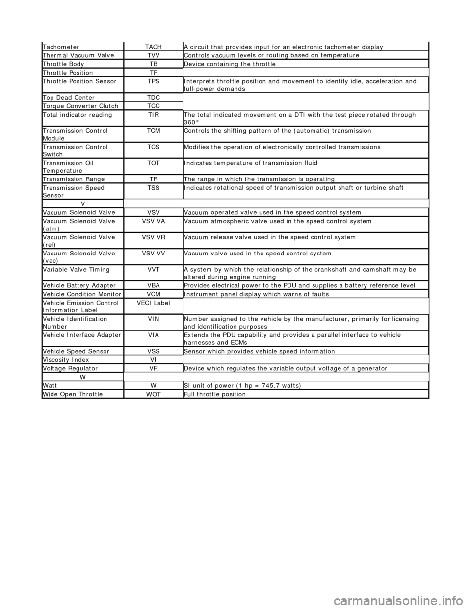
Tacho
meter
TACHA
ci
rcuit that provides input for
an electronic tachometer display
Thermal Vacuu
m Valve
TVVControls vacuum l
e
vels or
routing based on temperature
Throttle
Body
TBDe
vi
ce containing the throttle
Throttl
e
Position
TP
Throttl
e
Position Sensor
TPSInterprets throttl
e
position and movement to iden tify idle, acceleration and
full-power demands
Top Dead CenterTDC
Torque Converter C
lutch
TCC
To
tal
indicator reading
TIRThe t
o
tal indicated movement on a DTI with the test piece rotated through
360В°
Transm
ission Control
Module
TCMControls
the shifting pattern
of the (automatic) transmission
Transm
ission Control
Switch
TCSModifi es
the operation of electronically controlled transmissions
Transmission Oil
TemperatureTOTIndi
cat
es temperature of transmission fluid
Transmission RangeTRThe ran
g
e in which the transmission is operating
Transmission Spe
e
d
Sensor
TSSIndi cat
es rotational speed of transmission output shaft or turbine shaft
V
Vacuu
m
Solenoid Valve
VSVVacuu
m
operated valve used in the speed control system
Vacuu
m
Solenoid Valve
(atm)
VSV VAVacuu m
atmospheric valve used in the speed control system
Vacuu
m
Solenoid Valve
(rel)
VSV VRVacuu m
release valve used in the speed control system
Vacuu
m
Solenoid Valve
(vac)
VSV VVVacuu m
valve used in the speed control system
Variable Valve TimingVVTA
s
ystem by which the relationship of the crankshaft and camshaft may be
altered during engine running
Vehi cl
e Battery Adapter
VBAProvide
s
electrical power to the PDU
and supplies a battery reference level
Vehicl
e Condition Monitor
VCMInst
rum
ent panel display which warns of faults
Ve
hic
le Emission Control
Information Label
VECI Label
Vehi cl
e Identification
Number
VINN u
mber assigned to the vehicle by the manufacturer, primarily for licensing
and identification purposes
Vehi cl
e Interface Adapter
VIAExtends the
PDU ca
pability and provid
es a parallel interface to vehicle
harnesses and ECMs
Vehicle Spe e
d Sensor
VSSSens
or which provides ve
hicle speed information
Viscosity In
dexVI
Voltage RegulatorVRDe
vice which regulates the variable output voltage of a generator
W
Wat
tWSI unit of power (1 hp = 7
45.7 watts)
W
i
de Open Throttle
WO
TFu
ll throttle position
Page 67 of 2490
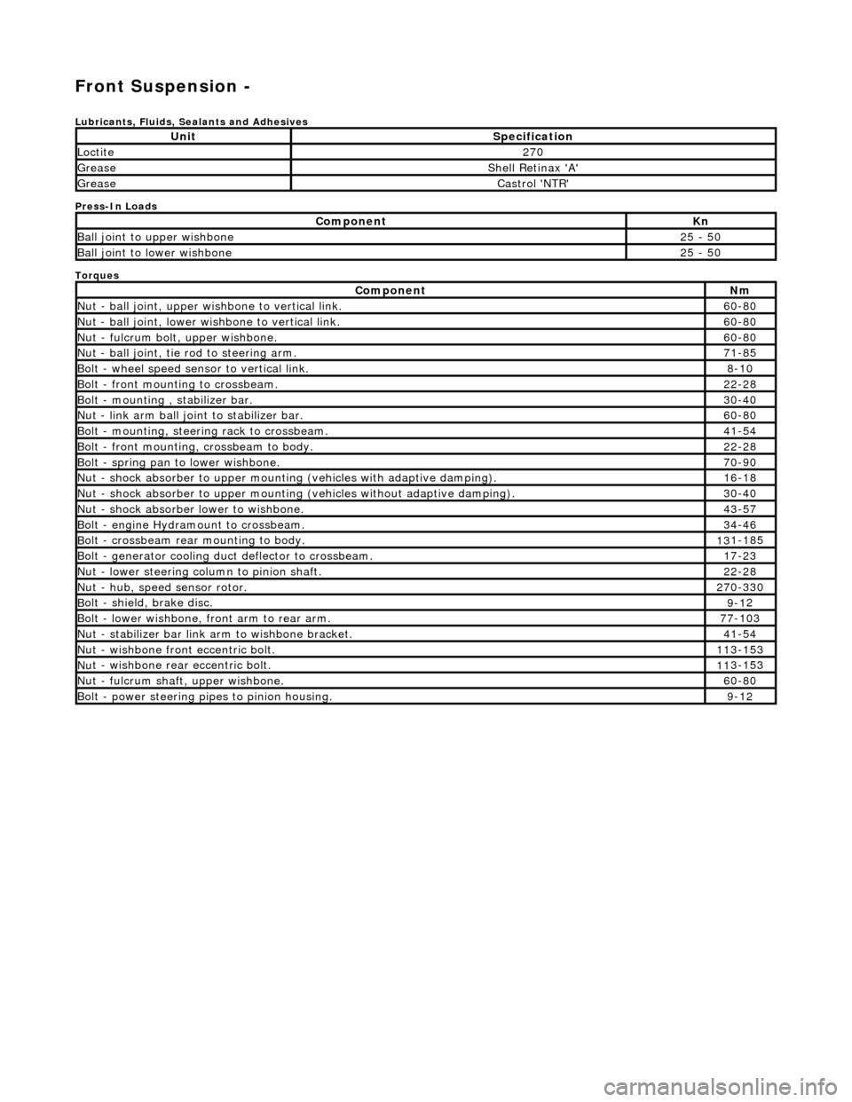
Front Suspension -
Lubri
cants, Fluids, Sealants and Adhesives
Press-In Loads
Torques
UnitS
pecification
Loctite27
0
Greas
e
Shell Retin
ax 'A'
Greas
e
Castro
l 'NTR'
Com
ponent
Kn
Ball join
t to upper wishbone
25
- 50
B
all joint to lower wishbone
25
- 50
Com
ponent
Nm
N
ut - ball joint, upper wishbone to vertical link.
60
-80
N
ut - ball joint, lower wishbone to vertical link.
60
-80
Nu
t - fulcrum bolt, upper wishbone.
60
-80
N
ut - ball joint, tie rod to steering arm.
71
-85
Bol
t - wheel speed sensor to vertical link.
8-1
0
Bol
t - front mounting to crossbeam.
22
-28
Bolt
- mounting , stabilizer bar.
30
-40
N
ut - link arm ball joint to stabilizer bar.
60
-80
Bolt
- mounting, steering rack to crossbeam.
41
-54
B
olt - front mounting, crossbeam to body.
22
-28
Bol
t - spring pan to lower wishbone.
70
-90
N
ut - shock absorber to upper mounting
(vehicles with adaptive damping).
16
-18
Nu
t - shock absorber to upper mounting (vehicles without adaptive damping).
30
-40
N
ut - shock absorber lower to wishbone.
43
-57
B
olt - engine Hydramount to crossbeam.
34
-46
B
olt - crossbeam rear mounting to body.
13
1-185
Bol
t - generator cooling du
ct deflector to crossbeam.
17
-23
N
ut - lower steering column to pinion shaft.
22
-28
N
ut - hub, speed sensor rotor.
27
0-330
B
olt - shield, brake disc.
9-1
2
Bol
t - lower wishbone, front arm to rear arm.
77
-103
Nu
t - stabilizer bar link arm to wishbone bracket.
41
-54
N
ut - wishbone front
eccentric bolt.
11
3-153
Nu
t - wishbone rear
eccentric bolt.
11
3-153
N
ut - fulcrum shaft, upper wishbone.
60
-80
Bolt -
power steering pi
pes to pinion housing.
9-1
2