length JAGUAR X308 1998 2.G User Guide
[x] Cancel search | Manufacturer: JAGUAR, Model Year: 1998, Model line: X308, Model: JAGUAR X308 1998 2.GPages: 2490, PDF Size: 69.81 MB
Page 669 of 2490

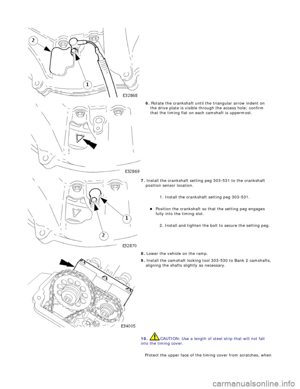
6. Rotate the crankshaft until the triangular arrow indent on
the drive plate is visible thro ugh the access hole; confirm
that the timing flat on ea ch camshaft is uppermost.
7. Install the crankshaft setting peg 303-531 to the crankshaft
position sensor location.
1. Install the crankshaft setting peg 303-531.
Position the crankshaft so that the setting peg engages
fully into the timing slot.
2. Install and tighten the bolt to secure the setting peg.
8. Lower the vehicle on the ramp.
9. Install the camshaft locking tool 303-530 to Bank 2 camshafts,
aligning the shafts sl ightly as necessary.
10. CAUTION: Use a length of steel strip that will not fall
into the timing cover.
Protect the upper face of the ti ming cover from scratches, when
Page 673 of 2490

6. Rotate the crankshaft until the triangular arrow indent on
the drive plate is visible thro ugh the access hole; confirm
that the timing flat on ea ch camshaft is uppermost.
7. Install the crankshaft setting peg 303-531 to the crankshaft
position sensor location.
1. Install the crankshaft setting peg 303-531.
Position the crankshaft so that the setting peg engages
fully into the timing slot.
2. Install and tighten the bolt to secure the setting peg.
8. Lower the vehicle on the ramp.
9. Install the camshaft locking tool 303-530 to Bank 1 camshafts,
aligning the shafts sl ightly as necessary.
10. CAUTION: Use a length of steel strip that will not fall
into the timing cover.
Protect the upper face of the ti ming cover from scratches, when
removing the bolt which secures the sprocket.
1. Place a flat piece of stee l strip along the timing cover
horizontal jointing face, adjacent to the exhaust
camshaft sprocket.
2. Secure the steel strip in place with adhesive tape.
11. A ball-ended hexagon drive bit is required to remove the
sprocket securing bolt. A suitable tool is available from Snap On as (FABLM10E) Long Series 10mm AF.
Page 678 of 2490

6. Rotate the crankshaft until the triangular arrow indent on
the drive plate is visible thro ugh the access hole; confirm
that the timing flat on ea ch camshaft is uppermost.
7. Install the crankshaft setting peg 303-531 to the crankshaft
position sensor location.
1. Install the crankshaft setting peg 303-531.
Position the crankshaft so that the setting peg engages
fully into the timing slot.
2. Install and tighten the bolt to secure the setting peg.
8. Lower the vehicle on the ramp.
9. Install the camshaft locking tool 303-530 to Bank 1 camshafts,
aligning the shafts sl ightly as necessary.
10. CAUTION: Use a length of steel strip that will not fall
into the timing cover.
Protect the upper face of the ti ming cover from scratches, when
Page 811 of 2490

6. Rotate the crankshaft until the triangular arrow indent on
the drive plate is visible thro ugh the access hole; confirm
that the timing flat on ea ch camshaft is uppermost.
7. Install the crankshaft setting peg 303-531 to the crankshaft
position sensor location.
1. Install the crankshaft setting peg 303-531.
Position the crankshaft so that the setting peg engages
fully into the timing slot.
2. Install and tighten the bolt to secure the setting peg.
8. Lower the vehicle on the ramp.
9. Install the camshaft locking tool 303-530 to Bank 2 camshafts,
aligning the shafts sl ightly as necessary.
10. CAUTION: Use a length of steel strip that will not fall
into the timing cover.
Protect the upper face of the ti ming cover from scratches, when
removing the bolt which secures the sprocket.
1. Place a flat piece of stee l strip along the timing cover
horizontal jointing face, adjacent to the exhaust
camshaft sprocket.
2. Secure the steel strip in place with adhesive tape.
11. A ball-ended hexagon drive bit is required to remove the
sprocket securing bolt. A suitable tool is available from Snap On as (FABLM10E) Long Series 10mm AF.
Page 816 of 2490

6. Rotate the crankshaft until the triangular arrow indent on
the drive plate is visible thro ugh the access hole; confirm
that the timing flat on ea ch camshaft is uppermost.
7. Install the crankshaft setting peg 303-531 to the crankshaft
position sensor location.
1. Install the crankshaft setting peg 303-531.
Position the crankshaft so that the setting peg engages
fully into the timing slot.
2. Install and tighten the bolt to secure the setting peg.
8. Lower the vehicle on the ramp.
9. Install the camshaft locking tool 303-530 to Bank 2 camshafts,
aligning the shafts sl ightly as necessary.
10. CAUTION: Use a length of steel strip that will not fall
into the timing cover.
Protect the upper face of the ti ming cover from scratches, when
Page 821 of 2490

6. Rotate the crankshaft until the triangular arrow indent on
the drive plate is visible thro ugh the access hole; confirm
that the timing flat on ea ch camshaft is uppermost.
7. Install the crankshaft setting peg 303-531 to the crankshaft
position sensor location.
1. Install the crankshaft setting peg 303-531.
Position the crankshaft so that the setting peg engages
fully into the timing slot.
2. Install and tighten the bolt to secure the setting peg.
8. Lower the vehicle on the ramp.
9. Install the camshaft locking tool 303-530 to Bank 1 camshafts,
aligning the shafts sl ightly as necessary.
10. CAUTION: Use a length of steel strip that will not fall
into the timing cover.
Protect the upper face of the ti ming cover from scratches, when
removing the bolt which secures the sprocket.
1. Place a flat piece of stee l strip along the timing cover
horizontal jointing face, adjacent to the exhaust
camshaft sprocket.
2. Secure the steel strip in place with adhesive tape.
11. A ball-ended hexagon drive bit is required to remove the
sprocket securing bolt. A suitable tool is available from Snap On as (FABLM10E) Long Series 10mm AF.
Page 826 of 2490

6. Rotate the crankshaft until the triangular arrow indent on
the drive plate is visible thro ugh the access hole; confirm
that the timing flat on ea ch camshaft is uppermost.
7. Install the crankshaft setting peg 303-531 to the crankshaft
position sensor location.
1. Install the crankshaft setting peg 303-531.
Position the crankshaft so that the setting peg engages
fully into the timing slot.
2. Install and tighten the bolt to secure the setting peg.
8. Lower the vehicle on the ramp.
9. Install the camshaft locking tool 303-530 to Bank 1 camshafts,
aligning the shafts sl ightly as necessary.
10. CAUTION: Use a length of steel strip that will not fall
into the timing cover.
Protect the upper face of the ti ming cover from scratches, when
Page 1015 of 2490

Fuel D
istribution
Fuel is supplied to th
e engine
via eight fuel injectors (one pe r cylinder). The injectors are located in two fuel rails which r un
the length of each cylinder bank and ar e integral with the air intake manifold.
Fuel pumped from the tank enters a feed pipe at the rear of bank 2. Fuel flow is along bank 2 fuel rail, across the top front
of the engine (cross-over pipe) and through bank 1 fuel rail, the unused fuel re turning to the tank via a pressure regulator.
The fuel injectors are each controlled electrically from the engine control module (ECM).
A test valve is fitted to the cross-over pipe connecting the fu el rails at the front of the intake manifold. This valve allows the
fuel system to be depr essurized during servicin g and troubleshooting.
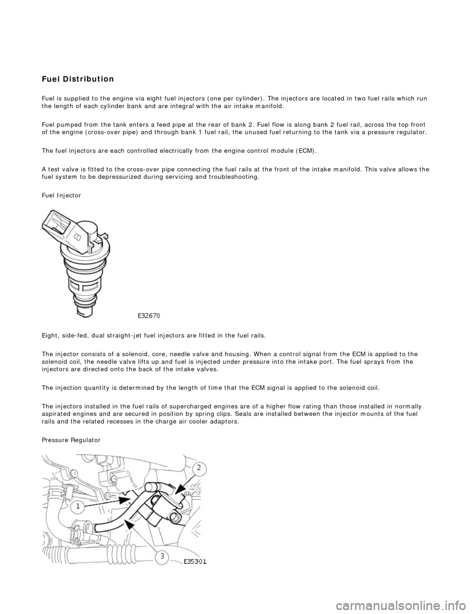
Fuel Injector
Eight, side-fed, dual straight-jet fuel injectors are fi tted in the fuel rails.
The injector consists of a solenoid, core, needle valve and ho using. When a control signal from the ECM is applied to the
solenoid coil, the needle valve lifts up and fuel is injected under pressure into the intake port. The fuel sprays from the
injectors are directed onto the back of the intake valves.
The injection quantity is determined by the length of time that the ECM signal is applied to the solenoid coil.
The injectors installed in the fuel rails of supercharged engines are of a higher flow rating than those installed in normally
aspirated engines and are secured in position by spring clips. Seals are instal led between the injector mounts of the fuel
rails and the related re cesses in the charge air cooler adaptors.
Pressure Regulator
Page 1051 of 2490

The
automatic belt tensioner consists of an idler pulley which is
free to rotate on a bearing, located at the end of a spring-
loaded pivot arm.
The pivot arm can be turned counter-clockwise (viewed from th e front of the engine) for belt removal and installation.
A belt-wear indicator is incorporated on th e rear horizontal face of the pivot arm.
It
em
De
scription
1Bel
t Wear Indicator
2Re
new Belt Indicator
3N
ew Belt Maximum Length
4N
ew Belt Minimum Length
Au
tomatic Belt Tensioner
Page 1059 of 2490

Ac
cessory Drive - Supercharger Belt
Re
moval and Installation
Remov
al
Installation
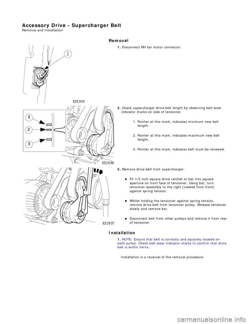
1.
Di
sconnect RH fa
n motor connector.
2. Check superch
arger dr
ive belt length by observing belt wear
indicator marks on side of tensioner.
1. Pointer at this mark, indicates minimum new belt length.
2. Pointer at this mark, indicates maximum new belt length.
3. Pointer at this mark, indi cates belt must be renewed.
3. R
emove drive belt from supercharger.
F
it 1/2 inch square drive ratchet or bar into square
aperture on front face of tensioner. Using bar, turn
tensioner assembly to the right (viewed from front)
against spring tension.
Wh
ilst holding the tensione
r against spring tension,
remove drive belt fr om tensioner pulley. Release tensioner
slowly and remove bar.
D
isconnect belt from
other pulleys and remove it from rear
of tensioner.
1. NOTE: Ensure that belt is correctly and squarely located on
each pulley. Check belt wear indicator marks to confirm that drive
belt is within limits.
Installation is a reversal of the removal procedure.