length JAGUAR X308 1998 2.G Owner's Guide
[x] Cancel search | Manufacturer: JAGUAR, Model Year: 1998, Model line: X308, Model: JAGUAR X308 1998 2.GPages: 2490, PDF Size: 69.81 MB
Page 2206 of 2490

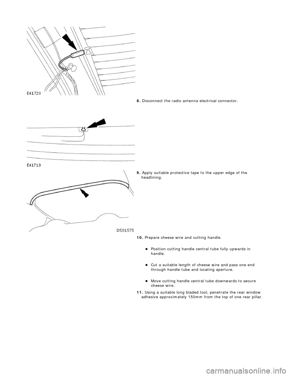
8. Disconnect the radio antenn a electrical connector.
9. Apply suitable protec tive tape to the upper edge of the
headlining.
10. Prepare cheese wire and cutting handle.
Position cutting handle cent ral tube fully upwards in
handle.
Cut a suitable length of ch eese wire and pass one end
through handle tube and locating aperture.
Move cutting handle central tube downwards to secure
cheese wire.
11. Using a suitable long bladed tool, penetrate the rear window
adhesive approximately 150mm fro m the top of one rear pillar.
Page 2214 of 2490

Cut a suitable length of cheese wire and pass one end
through handle tube and locating aperture.
Move cutting handle central tube downwards to secure
cheese wire.
12. Using a suitable long bladed tool, penetrate Betaseal
approximately 150mm from the top of one A pillar.
13. Pass free end of cheese wire through penetration and install
second cutting handle.
14. WARNING: When removing the windshield glass,
personal protection must be worn. Failure to follow this
instruction may result in personal injury.
• CAUTIONS:
Make sure the ch eese wire cannot contact the paintwork
while the the windshield adhesive is being cut. Failure to follow
this instruction may result in damage to the vehicle.
Make sure the cheese wire cannot contact the instrument
panel while the the windshield adhesive is being cut. Failure to
follow this instruction may result in damage to the vehicle.
Make sure the cheese wire passes the Vehicle Identification
Number (VIN) plate on the correct side. Failure to follow this
instruction may result in damage to the component.
When cutting, do not allow ch eese wire to contact edge of
windshield glass as this will crack the windshield glass.
• NOTE: Apply cutting lubricant to the cheese wire frequently
through out the cutting process.
With assistance and exercising care at the corners to avoid
damaging paintwork, cut around the windshield glass
Page 2342 of 2490

Roof Opening Panel - Roof Opening Panel Weatherstrip
Removal and Installation
Removal
Installation
1.
Remove sliding roof trim panel for access. Refer to 76.82.19.
2. Remove sliding roof panel fo r access. Refer to 76.82.05.
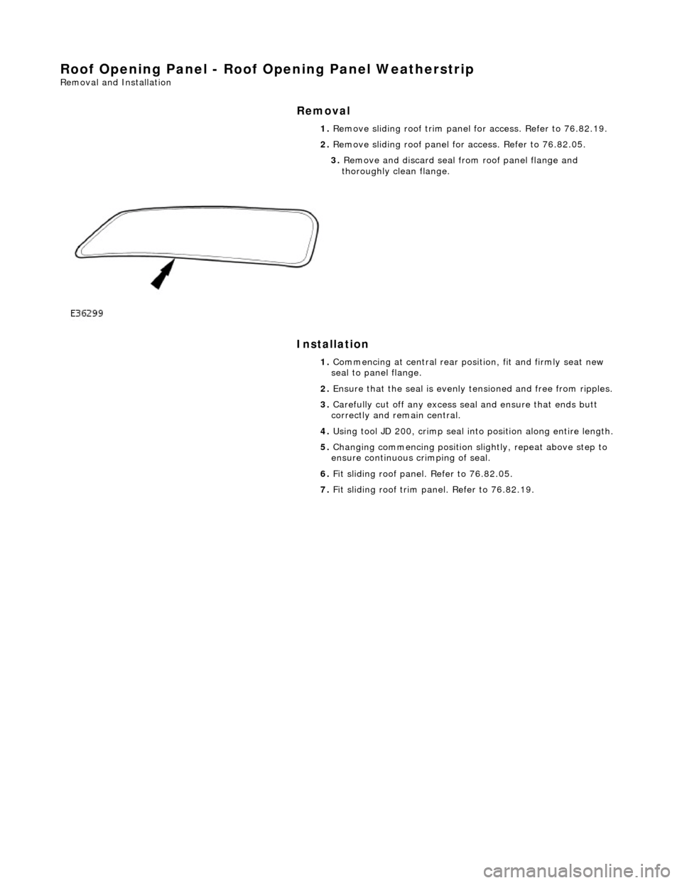
3. Remove and discard seal fro m roof panel flange and
thoroughly clean flange.
1. Commencing at central rear posi tion, fit and firmly seat new
seal to panel flange.
2. Ensure that the seal is evenly tensioned and free from ripples.
3. Carefully cut off any excess seal and ensure that ends butt
correctly and re main central.
4. Using tool JD 200, crimp seal into position along entire length.
5. Changing commencing position sl ightly, repeat above step to
ensure continuous crimping of seal.
6. Fit sliding roof panel. Refer to 76.82.05.
7. Fit sliding roof trim panel. Refer to 76.82.19.
Page 2407 of 2490

For coachline specifications, see page? .
Tape Application
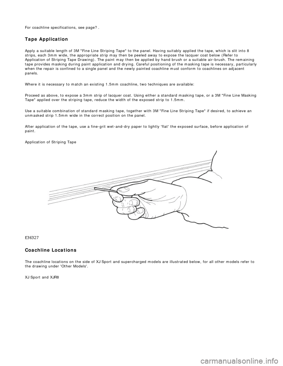
Apply a suitable length of 3M "Fine Line Striping Tape" to the panel. Having suitably applied the tape, which is slit into 8
strips, each 3mm wide, the appr opriate strip may then be peeled away to expose the lacquer coat below (Refer to
Application of Striping Tape Drawing). The paint may then be applied by hand brush or a suitable air-brush. The remaining
tape provides masking during paint applicat ion and drying. Careful positioning of the masking tape is necessary, particularly
when the repair is confined to a single panel and the newly painted coachline mu st conform to coachlines on adjacent
panels.
Where it is necessary to match an existing 1.5mm coachline, two tec hniques are available:
Proceed as above, to expose a 3mm strip of lacquer coat. Using either a standard masking tape, or a 3M "Fine Line Masking
Tape" applied over the striping tape, reduce the width of the exposed strip to 1.5mm.
Use a suitable combination of standard mask ing tape, together with 3M "Fine Line Striping Tape" if desired, to achieve an
unmasked strip 1.5mm wide in the correct position on the panel.
After application of the tape, use a fine-g rit wet-and-dry paper to lightly 'flat' the exposed surface, before application of
paint.
Application of Striping Tape
Coachline Locations
The coachline locations on the side of XJ Sport and supercharged models are illustrated below, for all other models refer to
the drawing under 'Other Models'.
XJ Sport and XJR8
Page 2488 of 2490

Installation
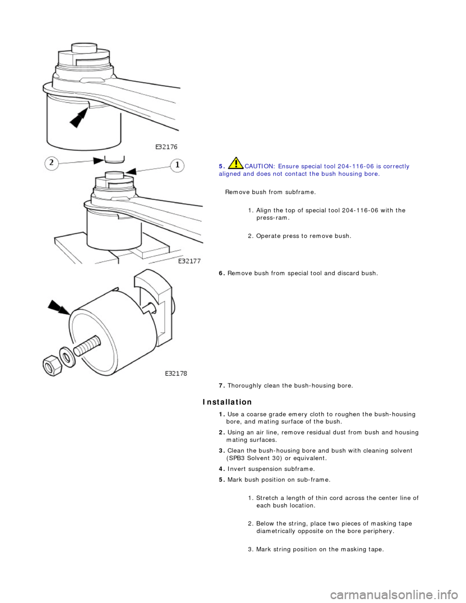
5. CAUTION: Ensure special tool 204-116-06 is correctly
aligned and does not contact the bush housing bore.
Remove bush from subframe.
1. Align the top of special tool 204-116-06 with the press-ram.
2. Operate press to remove bush.
6. Remove bush from special tool and discard bush.
7. Thoroughly clean the bush-housing bore.
1. Use a coarse grade emery cloth to roughen the bush-housing
bore, and mating surface of the bush.
2. Using an air line, remove residu al dust from bush and housing
mating surfaces.
3. Clean the bush-housing bore and bush with cleaning solvent
(SPB3 Solvent 30) or equivalent.
4. Invert suspension subframe.
5. Mark bush position on sub-frame.
1. Stretch a length of thin co rd across the center line of
each bush location.
2. Below the string, place two pieces of masking tape diametrically opposite on the bore periphery.
3. Mark string position on the masking tape.