lamp JAGUAR X308 1998 2.G Workshop Manual
[x] Cancel search | Manufacturer: JAGUAR, Model Year: 1998, Model line: X308, Model: JAGUAR X308 1998 2.GPages: 2490, PDF Size: 69.81 MB
Page 2294 of 2490

Handles, Locks, Latches and Entry Systems - Luggage Compartment Lid
Warning Indicator Switch
Removal and Installation
Removal
1. Remove trunk lamp assemblies. Refer to 86.45.16.
2. Remove covers from the two tr unk latch finisher securing
bolts and slacken and remove securing bolts.
3. Remove latch finisher from trunk.
4. Release and discard the four trunk lid liner rear fasteners
and position liner for access.
5. Release trunk open switch multiplug from retaining clip and
disconnect multiplug.
6. Remove the latch assembly securing bolt.
Page 2307 of 2490
cooling duct.
The windshield washer is operated by pressing the button at the end of the wiper control stalk switch. Pressing and
releasing the button operates the washer for 1 to 1.4 seconds and the wiper completes three sweeps. An optional drip wipe
function adds a further sweep of the wiper after a 4 second delay, to clear residual fluid from the windshield. If the button is
held depressed, the washer and wiper will operate continuous ly for up to 20 seconds. When the button is released, the
wiper will again complete three further sweeps.
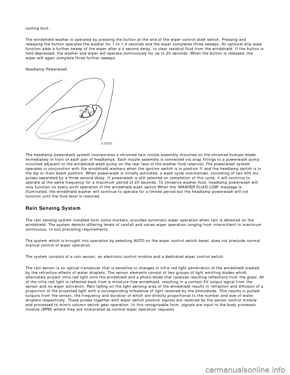
Headlamp Powerwash
The headlamp powerwash system incorporates a chromed twin nozzle assembly mounted on the chromed bumper blade
immediately in front of each pair of he adlamps. Each nozzle assembly is connected via snap fittings to a powerwash pump
mounted adjacent to the windshield wash pump on the rear face of the washer fluid reservoir.The powerwash system
operates in conjunction with the windshield washers when the ignition switch is in position II and the headlamp switch is in
the dip or main beam position. When powerwash is initially activated, a wash cycle commences, consisting of two 400 ms
pulses separated by a three second delay. If powerwash is still selected on completion of this cycle, it will continue to
operate at the same frequency for a maximum period of 20 se conds. To conserve washer fluid, headlamp powerwash will
only function on every sixth operation of the windshie ld wash switch.When the 'WASHER FLUID LOW' message is
illuminated, the windshield washer will continue to operat e for a limited period but the headlamp powerwash will not
function until the fluid level is restored.
Rain Sensing System
The rain sensing system installed form so me markets, provides automatic wiper operation when rain is detected on the
windshield. The system detects differing le vels of rainfall and varies wiper operation ranging from intermittent to maximum
continuous, to suit prevailing requirements.
The system which is brought into operation by selecting AUTO on the wiper control switch bezel, does not preclude normal
manual control of wiper operation.
The system consists of a rain sensor, an electronic control module and a dedicated wiper control switch.
The rain sensor is an optical transducer that is sensitive to changes in infra-red light penetration of the windshield created
by the refractive effects of water drople ts. The sensor elements consist of two groups of light emitting diodes which
alternately project infra-red light onto th e windshield and a photo-diode that receiv es resulting reflections from the glass. A ll
of the infra-red light is reflected back from a moisture-free windshield, resulting in a contact 5V output signal from the
sensor and no wiper activation. Rain falling on the light sensing area of the wi ndshield results in refraction and diffusion of a
proportion of the projected light with a corresponding imbalance of light received by the photodiode. This results in pulsed
outputs from the sensor, the frequency and duration of which are directly proportional to the number and size of water
droplets respectively. These pulses together with wiper switch position signals are received by the sensor control module
and processed to mimic column switch gear operation. In this recognisable form, signals are input to the body processor
module (BPM) where they are interprete d as normal wiper operation requests.
Page 2310 of 2490
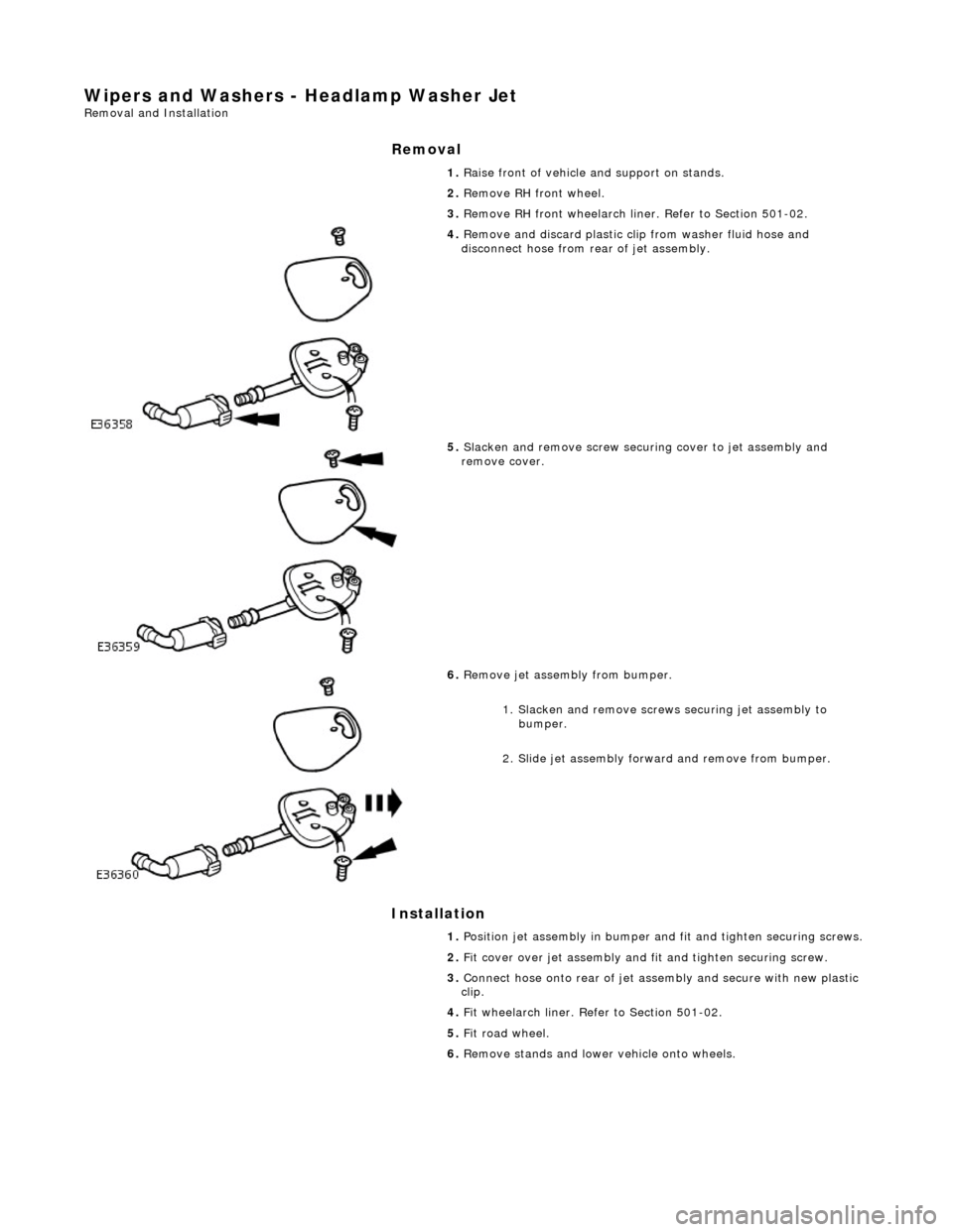
Wipers and Washers - Headlamp Washer Jet Removal and Installation
Removal
Installation
1.
Raise front of vehicle and support on stands.
2. Remove RH front wheel.
3. Remove RH front wheelarch liner. Refer to Section 501-02.
4. Remove and discard plastic clip from washer fluid hose and
disconnect hose from rear of jet assembly.
5. Slacken and remove screw securing cover to jet assembly and
remove cover.
6. Remove jet assembly from bumper.
1. Slacken and remove screws securing jet assembly to bumper.
2. Slide jet assembly forward and remove from bumper.
1. Position jet assembly in bumper an d fit and tighten securing screws.
2. Fit cover over jet assembly and fit and tighten securing screw.
3. Connect hose onto rear of jet asse mbly and secure with new plastic
clip.
4. Fit wheelarch liner. Refer to Section 501-02.
5. Fit road wheel.
6. Remove stands and lower vehicle onto wheels.
Page 2311 of 2490
Wipers and Washers - Headlamp Washer Pump
Removal and Installation
Removal
Installation
1.
Remove battery cover and disc onnect ground cable from
battery terminal. Refer to 86.15.19.
2. Raise front of vehicle and support on stands.
3. Remove RH front wheel.
4. Remove RH wheelarch liner. Refer to Section 501-02.
5. Position a suitable drain recept acle under washer reservoir.
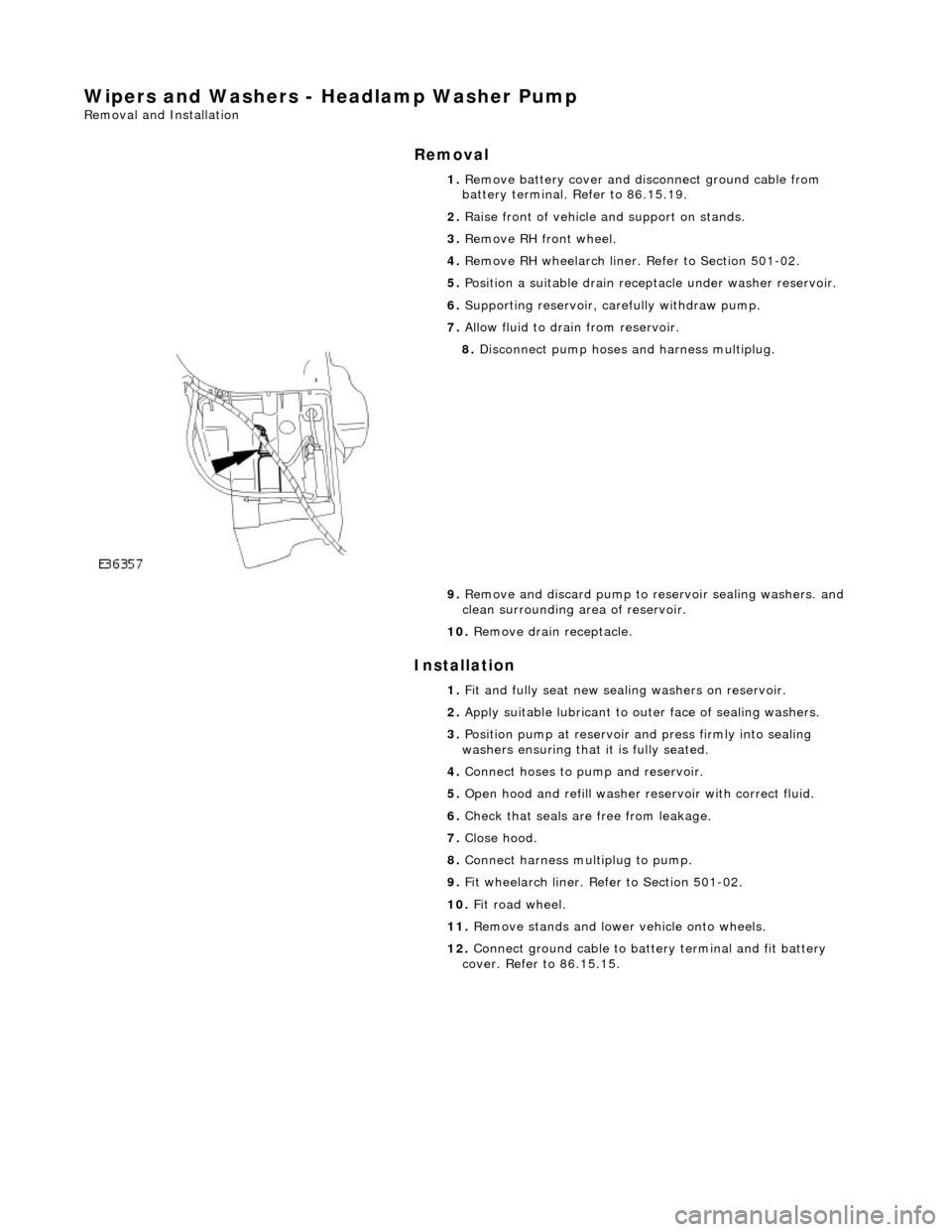
6. Supporting reservoir, ca refully withdraw pump.
7. Allow fluid to drain from reservoir.
8. Disconnect pump hoses and harness multiplug.
9. Remove and discard pump to re servoir sealing washers. and
clean surrounding area of reservoir.
10. Remove drain receptacle.
1. Fit and fully seat new sealing washers on reservoir.
2. Apply suitable lubricant to outer face of sealing washers.
3. Position pump at reservoir and press firmly into sealing
washers ensuring that it is fully seated.
4. Connect hoses to pump and reservoir.
5. Open hood and refill washer re servoir with correct fluid.
6. Check that seals are free from leakage.
7. Close hood.
8. Connect harness multiplug to pump.
9. Fit wheelarch liner. Refe r to Section 501-02.
10. Fit road wheel.
11. Remove stands and lowe r vehicle onto wheels.
12. Connect ground cable to batt ery terminal and fit battery
cover. Refer to 86.15.15.
Page 2315 of 2490
Wipers and Washers - Windshield Washer Reservoir
Removal and Installation
Removal
Installation
1.
Open hood and fit fender cover.
2. Raise front of vehicle and support on stands.
3. Remove RH front wheel.
4. Remove RH front wheel arch li ner. Refer to Section 501-02.
5. Remove front undertray. Refer to Section 501-02.
6. Remove windshield washer and headlamp powerwash pumps
from reservoir. Refer to op erations in this section.
7. Disconnect Low Level indicator mu ltiplug. Refer to operations
in this section.
8. Carefully remove filler cap from reservoir filler neck.
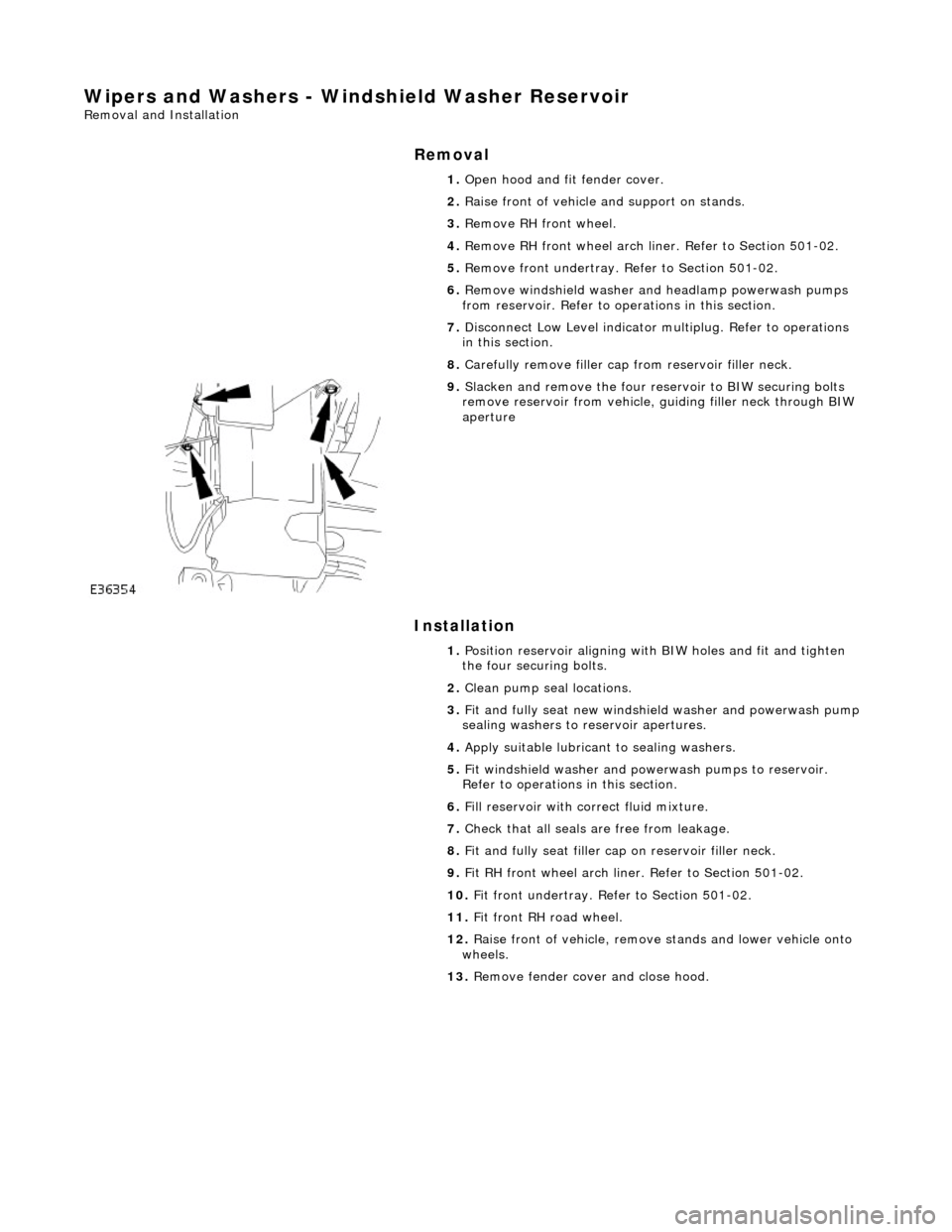
9. Slacken and remove the four re servoir to BIW securing bolts
remove reservoir from vehicle, guiding filler neck through BIW
aperture
1. Position reservoir aligning with BIW holes and fit and tighten
the four securing bolts.
2. Clean pump seal locations.
3. Fit and fully seat new windshie ld washer and powerwash pump
sealing washers to reservoir apertures.
4. Apply suitable lubricant to sealing washers.
5. Fit windshield washer and powerwash pumps to reservoir.
Refer to operations in this section.
6. Fill reservoir with correct fluid mixture.
7. Check that all seals are free from leakage.
8. Fit and fully seat filler cap on reservoir filler neck.
9. Fit RH front wheel arch liner. Refer to Section 501-02.
10. Fit front undertray. Refer to Section 501-02.
11. Fit front RH road wheel.
12. Raise front of vehicle, remove stands and lower vehicle onto
wheels.
13. Remove fender cover and close hood.
Page 2323 of 2490

10. Disconnect key interlock solenoid harness multiplug.
11. Release flasher/lamp/trip swit ch harness multiplugs from
retaining bracket and di sconnect multiplugs.
12. Disconnect cancellation module harness multiplugs.
13. Slacken and remove bolts securing switch
assemblies/cancellation module to column.
Page 2324 of 2490

14. Remove steering column swit chgear assembly for access.
15. Remove flasher/lamp/trip switch assembly from switchgear
bracket.
16. NOTE: Due to soldered connections, it is not possible to
remove wiper/washer sw itch at this stage.
Release windshield wiper/washer switch from switchgear
bracket and position for access.
17. Remove cancellation module from mounting bracket.
Page 2325 of 2490

Installation
18. Remove windshield wiper/ washer switch/mounting
bracket/audible warning speaker assembly from vehicle.
1. Position windshield wipe r/washer switch/mounting
bracket/audible warning speaker assembly for access in
vehicle.
2. Fit cancellation module to mounting bracket.
3. Fit wiper/washer switch to cancellation module/mounting
bracket.
4. Fit flasher/lamp/trip switch to cancellation module/mounting
bracket.
5. Position switchgear assembly on steering column and fit and
tighten securing bolts.
6. Connect cancellation module harness multiplugs and fit
multiplugs to retaining bracket.
7. Connect flasher/lamp/trip switch harness multiplugs and fit
multiplugs to retaining bracket.
Page 2344 of 2490
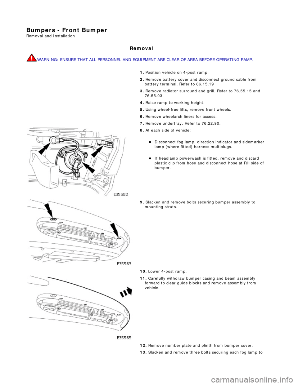
Bumpers - Front Bumper
Removal and Installation
Removal
WARNING: ENSURE THAT ALL PERSONNEL AND EQUIPMENT ARE CLEAR OF AREA BEFORE OPERATING RAMP.
1. Position vehicle on 4-post ramp.
2. Remove battery cover and disc onnect ground cable from
battery terminal. Refer to 86.15.19
3. Remove radiator surround and grill. Refer to 76.55.15 and
76.55.03.
4. Raise ramp to working height.
5. Using wheel-free lifts, remove front wheels.
6. Remove wheelarch liners for access.
7. Remove undertray. Refer to 76.22.90.
8. At each side of vehicle:
Disconnect fog lamp, directio n indicator and sidemarker
lamp (where fitted) harness multiplugs.
If headlamp powerwash is fitted, remove and discard
plastic clip from hose and disconnect hose at RH side of
bumper.
9. Slacken and remove bolts securing bumper assembly to
mounting struts.
10. Lower 4-post ramp.
11. Carefully withdraw bumper casing and beam assembly
forward to clear guide blocks and remove assembly from
vehicle.
12. Remove number plate and plinth from bumper cover.
13. Slacken and remove three bolts securing each fog lamp to
Page 2345 of 2490

bumper cover and remove both lamps from cover.
14. Release sidemarker lamp/refle ctor clips and remove both
lamps/reflectors from bumper cover.
15. Remove direction indicators fr om bumper assembly. Refer to
Section 417.01.
16. Remove powerwash jet assemb lies and hoses from top of
bumper assembly. Refer to Section 501-16.
17. Remove bumper blades.
1. Slacken and remove three screws securing each blade
to bumper cover.
2. Slide each blade forward to release two side tangs from cover and remove blade from bumper.
18. Rotate three splitter vane fasteners 1/4 turn counter-
clockwise and remove splitter vane from air intake.
19. Release tangs securing brake cooling ducts to cover and
remove ducts from bumper.