lamp JAGUAR X308 1998 2.G Workshop Manual
[x] Cancel search | Manufacturer: JAGUAR, Model Year: 1998, Model line: X308, Model: JAGUAR X308 1998 2.GPages: 2490, PDF Size: 69.81 MB
Page 2392 of 2490
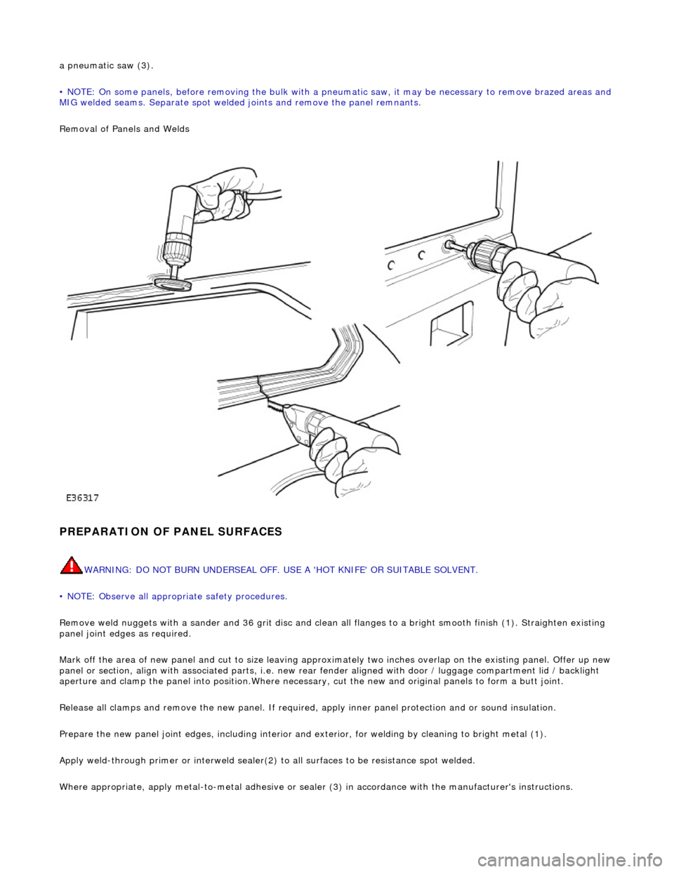
a pneumatic saw (3).
• NOTE: On some panels, before removing the bulk with a pneumatic saw, it may be necessary to remove brazed areas and
MIG welded seams. Separate spot welded joints and remove the panel remnants.
Removal of Panels and Welds
PREPARATION OF PANEL SURFACES
WARNING: DO NOT BURN UNDERSEAL OFF. USE A 'HOT KNIFE' OR SUITABLE SOLVENT.
• NOTE: Observe all appropriate safety procedures.
Remove weld nuggets with a sander and 36 gr it disc and clean all flanges to a bright smooth finish (1). Straighten existing
panel joint edges as required.
Mark off the area of new panel and cut to size leaving approxim ately two inches overlap on the existing panel. Offer up new
panel or section, align with associated pa rts, i.e. new rear fender aligned with door / luggage compartment lid / backlight
aperture and clamp the panel into positi on.Where necessary, cut the new and orig inal panels to form a butt joint.
Release all clamps and remove the new panel. If required, apply inner panel protection and or sound insulation.
Prepare the new panel joint edges, including interior and exterior, for welding by cleaning to bright metal (1).
Apply weld-through primer or in terweld sealer(2) to all surfaces to be resistance spot welded.
Where appropriate, apply metal- to-metal adhesive or sealer (3) in accordance with the manufacturer's instructions.
Page 2393 of 2490
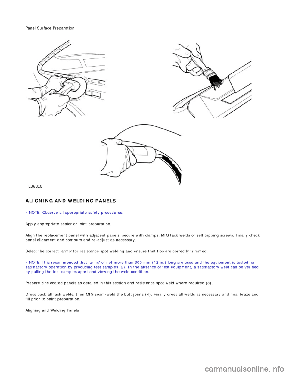
Panel Surface Preparation
ALIGNING AND WELDING PANELS
• NOTE: Observe all appropriate safety procedures.
Apply appropriate sealer or joint preparation.
Align the replacement panel with adjacent panels, secure with clamps, MIG tack welds or self tapping screws. Finally check
panel alignment and contours and re-adjust as necessary.
Select the correct 'arms' for resistance spot welding and ensure that tips are correctly trimmed.
• NOTE: It is recommended that 'arms' of not more than 300 mm (12 in.) long ar e used and the equipment is tested for
satisfactory operation by producing test samples (2). In the ab sence of test equipment, a satisfactory weld can be verified
by pulling the test sa mples apart and viewing the weld condition.
Prepare zinc coated panels as detailed in this section and resistance spot weld where required (3).
Dress back all tack welds, then MIG seam-weld the butt joints (4). Finally dress all welds as necessary and final braze and
fill prior to paint preparation.
Ali
gning and Welding Panels
Page 2408 of 2490
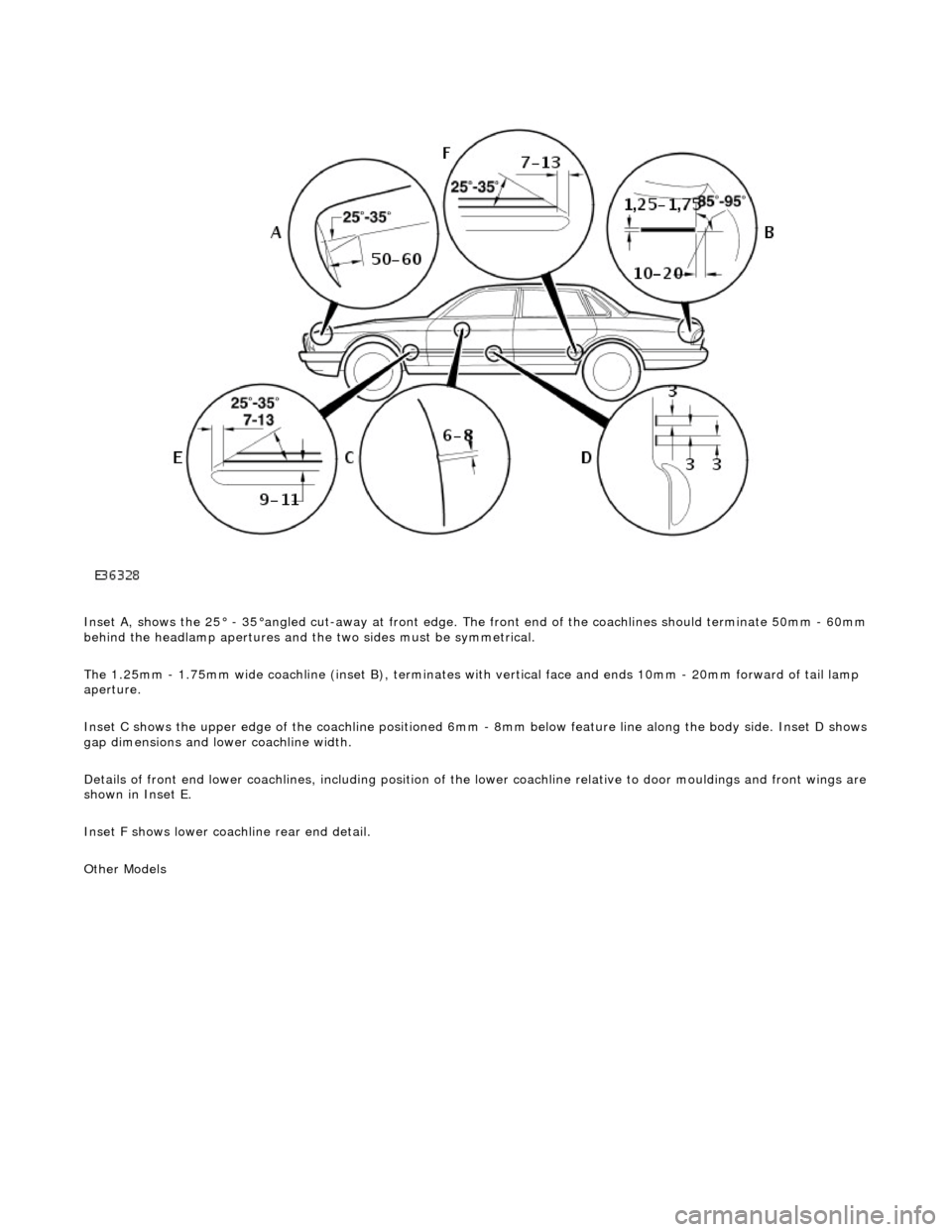
Inset A, shows the 25° - 35°angled cut-away at front edge. The front end of the coachlines should terminate 50mm - 60mm behind the headlamp apertures and the two sides must be symmetrical.
The 1.25mm - 1.75mm wide coachline (inset B), terminates with vertical face and ends 10mm - 20mm forward of tail lamp
aperture.
Inset C shows the upper edge of the coac hline positioned 6mm - 8mm below feature line along the body side. Inset D shows
gap dimensions and lower coachline width.
Details of front end lower coachlines, including position of the lower coachline relative to door mouldings and front wings are
shown in Inset E.
Inset F shows lower coachline rear end detail.
Other Models
Page 2409 of 2490
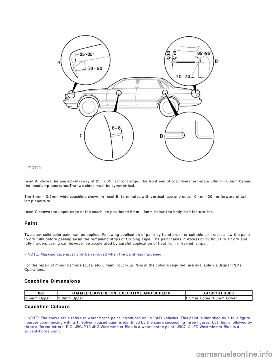
Inset A, shows the angled cut-away at 25° - 35° at front edge. The front end of coachlines terminate 50mm - 60mm behind
the headlamp apertures.The two sides must be symmetrical.
The 3mm - 3.5mm wide coachline shown in Inset B, terminates with vertical face and ends 10mm - 20mm forward of tail
lamp aperture.
Inset C shows the upper edge of th e coachline positioned 6mm - 8mm be low the body side feature line.
Paint
Two-pack solid color paint can be applied. Following application of paint by hand brus h or suitable air brush, allow the paint
to dry fully before peeling away the remain ing strips of Striping Tape. The paint takes in excess of 12 hours to air dry and
fully harden, curing can however be accelerated by careful application of heat from infra-red lamps..
• NOTE: Masking tape must only be removed when the paint has hardened.
For the repair of minor damage (cuts, et c.), Paint Touch-up Pens in the colours required, are available via Jaguar Parts
Operations.
Coachline Dimensions
Coachline Colours
• NOTE: The above table refers to water borne paint introduced on 1998MY vehicles. This paint is identified by a four figure
number commencing with a 1. Solvent-based paint is identified by the same succeeding three figures, but this is followed by three different letters. E.G. JBC1712 JHG Westminster Blue is a water-borne paint. JBC712 JFG Westminster Blue is a
solvent-borne paint.
XJ8DAIMLER,SOVEREIGN, EXECUTIVE AND SUPER 8XJ SPORT XJR8
1.5mm Upper3.0mm Upper1.5mm Upper 3.0mm Lower
Page 2411 of 2490
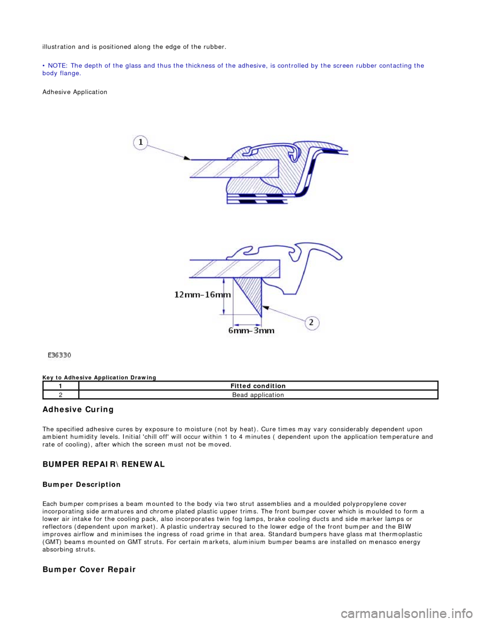
illustration and is positioned along the edge of the rubber.
• NOTE: The depth of the glass and thus the thickness of the ad hesive, is controlled by the screen rubber contacting the
body flange.
Adhesive Application
Key to Adhesive Application Drawing
Adhesive Curing
The specified adhesive cures by exposure to moisture (not by heat). Cure times may vary considerably dependent upon
ambient humidity levels. Initial 'chill off' will occur within 1 to 4 minutes ( dependent upon the application temperature and
rate of cooling), after which the screen must not be moved.
BUMPER REPAIR\RENEWAL
Bumper Description
Each bumper comprises a beam mounte d to the body via two strut assemblies and a moulded polypropylene cover
incorporating side armatures and chrome plated plastic upper trims. The front bumper cover which is moulded to form a
lower air intake for the cooling pack, also incorporates twin fog lamps, brake cooling ducts and side marker lamps or
reflectors (dependent upon market). A plastic undertray secured to the lower edge of the front bumper and the BIW
improves airflow and minimises the ingres s of road grime in that area. Standard bumpers have glass mat thermoplastic
(GMT) beams mounted on GMT struts. For certain markets, aluminium bumper beams are installed on menasco energy
absorbing struts.
Bumper Cover Repair
1Fitted condition
2Bead application
Page 2417 of 2490
Panels centered between two adjacent panels must have equal gaps on either side. For exceptions to this, refer to the
appropriate specification. Gaps between ad jacent panels or components must not expose harnesses, labels, brackets or
visually poor joint or assembly conditions.
• NOTE: Sliding roof panel clearances are specified without the edge seal installed.
Areas of particular concern are, fuel filler flap, trunk lid to fenders and saddle panels, hood to fenders, grill and headlamps,
sliding roof to main roof panel, door gaps at fenders, B\C posts, roof drip rail an d rocker panel, and bumper cover to fenders
and cross car assemblies
Alignment
Panels must be correctly profiled to maintain cosmetic appearance, and ensure co rrect seating of seals with minimal wind
noise. Areas of particular concern are hood to fenders, trunk lid to fenders and saddle panels, doors to apertures, doors to
fenders and adjacent doors and relationship of the sliding roof panel leading and trailing edges to the main roof panel.
Exterior Fitments
Bezels, trims and lamps must be concentric with apertu res and have equal clearances with adjacent panels.
Areas of particular concern are headlamp to hood, fender and trim panel, exhaust tailpipe trim to bumper cover cut-out,
rear lamp assembly to trunk lid, fender and bumper cover trim, and side feature lines including body side mouldings, fender
to door and door to door.
Exterior Clearances and Alignments-Front