lamp JAGUAR X308 1998 2.G Workshop Manual
[x] Cancel search | Manufacturer: JAGUAR, Model Year: 1998, Model line: X308, Model: JAGUAR X308 1998 2.GPages: 2490, PDF Size: 69.81 MB
Page 2205 of 2490

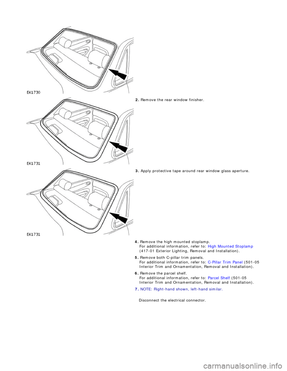
2. Remove the rear window finisher.
3. Apply protective tape around rear window glass aperture.
4. Remove the high mounted stoplamp.
For additional information, refer to: High Mounted Stoplamp
(417-01 Exterior Lighting, Removal and Installation).
5. Remove both C-pill ar trim panels.
For additional information, refer to: C
-Pillar Trim Panel (501-05
Interior Trim and Ornamentatio n, Removal and Installation).
6. Remove the parcel shelf.
For additional information, refer to: Parcel Shelf
(501-05
Interior Trim and Ornamentatio n, Removal and Installation).
7. NOTE: Right-hand shown, left-hand similar.
Disconnect the electrical connector.
Page 2211 of 2490

For additional information, refer to: C
-Pillar Trim Panel (501-05
Interior Trim and Ornamentatio n, Removal and Installation).
15. Install the high mounted stoplamp.
For additional information, refer to: High Mounted Stoplamp
(417-01 Exterior Lighting, Removal and Installation).
Page 2240 of 2490

Instrument Panel and Console - Instrument Cluster Finish Panel Bezel
Removal and Installation
Removal
1. Adjust steering column to full y extended and lowered position.
2. Remove battery cover and disc onnect ground cable from
battery terminal. Refer to 86.15.19.
3. Remove veneer from instrument panel. Refer to 76.47.24.
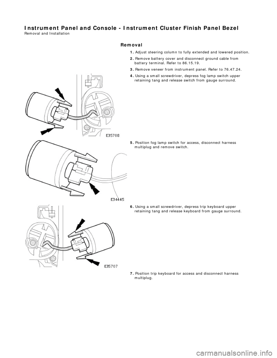
4. Using a small screwdriver, de press fog lamp switch upper
retaining tang and release sw itch from gauge surround.
5. Position fog lamp switch fo r access, disconnect harness
multiplug and remove switch.
6. Using a small screwdriver, depress trip keyboard upper
retaining tang and release ke yboard from gauge surround.
7. Position trip keyboard for ac cess and disconnect harness
multiplug.
Page 2241 of 2490

Installation
8. Slacken and remove four screws securing major gauge
module/surround to fascia and withdraw surround.
1. Position major gauge surround on panel, routing harness
multiplugs through apertures.
2. Fit and tighten screws securing major gauge module/surround
to fascia.
3. Connect harness multiplug to tr ip keyboard and fit and fully
seat keyboard in gauge surround, ensuring correct location of
retaining tangs
4. Connect harness multiplug to fog lamp switch and fit and fully
seat switch in gaug e surround, ensuring correct location of
tangs.
5. Fit veneer panel. Refer to 76.47.24.
6. Connect ground cable to battery terminal and fit battery cover.
Refer to 86.15.15.
7. Return steering column to original position.
Page 2274 of 2490

Remote Central Locking Transmitter Unit
A four-button transmitter unit provides for remote controlled central locking of the vehicle.
The button bearing a red closed padlock sy mbol locks the vehicle and arms the security system. To remote 'single action'
lock, the transmitter is pointed towards the vehicle and this bu tton is pressed and released. To deadlock the vehicle, the
above operation is repeated with in three seconds. This function can also be used to remote close any windows. Completion
of deadlocking is indicated by an audible 'chirp' from the security system and a single flash from the direction indicators.
The vehicle is unlocked and the security system disarmed by pressing the button with the open padlock symbol.
The trunk lock can also be remotely released by op erating the button bearing the trunk lid open symbol.
The button with dipped headlamp symbol is for emergency us e. When depressed three times within three seconds, it
switches the headlamps on for 25 seconds and operates the vehicle alarm 5 times.
Page 2278 of 2490

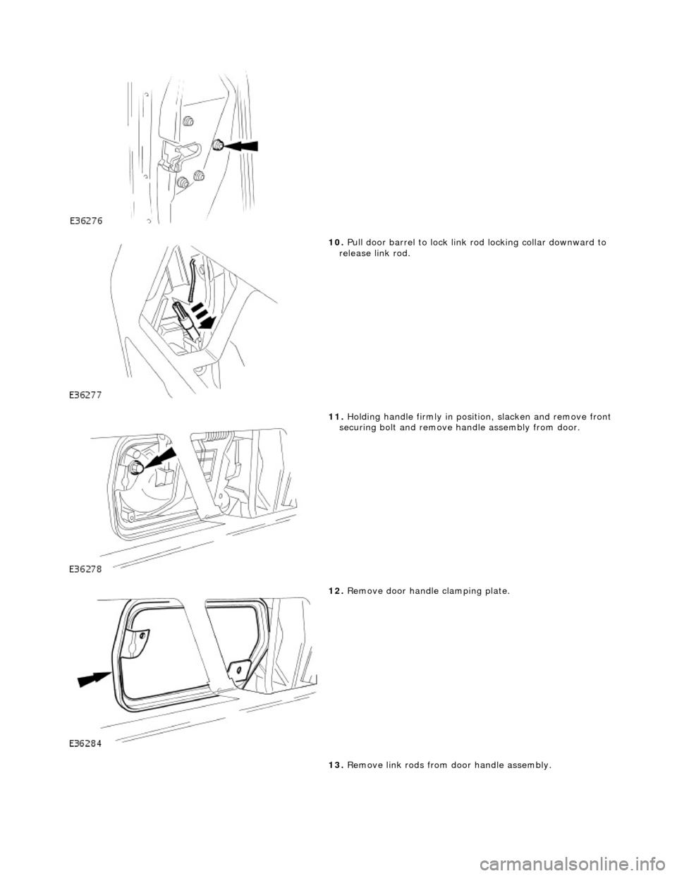
10. Pull door barrel to lock link rod locking collar downward to
release link rod.
11. Holding handle firmly in posi tion, slacken and remove front
securing bolt and remove ha ndle assembly from door.
12. Remove door handle clamping plate.
13. Remove link rods from door handle assembly.
Page 2279 of 2490

Installation
14. Slacken and remove lock barre l securing screw and remove
lock barrel from handle.
1. Align and fit lock barrel to door handle and fit and tighten
securing screw.
2. Fit link rods to door handle assembly.
3. Align and fit handle assembly to door
4. Position clamping plate inside door, and holding handle in
position, fit and tighten securing bolts.
5. Position barrel link rod on lock assembly and secure with
locking collar.
6. Check for satisfactory door handle operation.
7. Slacken and remove door handle rear securing bolt.
8. Position door lock security guard and fit and hand tighten lower
securing bolt.
9. Fit and tighten door handle rear /security guard upper securing
bolt.
10. Fully tighten security guard lower securing bolt.
11. Connect lock link rod to door handle.
12. Reposition PVC inner sheet.
13. Connect ground cable to battery terminal. Refer to 86.15.15.
14. Check for satisfactory operation of locking system
15. Disconnect ground cable from battery terminal. Refer to
86.15.15.
16. Ensure that shedder contact area of door is clean and dry.
17. Position water shedder at door and carefully pass harness
through.
18. Fit and firmly seat water shedder on door ensuring
satisfactory adhesion.
Page 2287 of 2490

Handles, Locks, Latches and Entry Systems - Luggage Compartment Lid
Latch
Removal and Installation
Removal
1. Remove trunk lamp assemblies. Refer to 86.45.16.
2. Remove covers from the two tr unk latch finisher securing
bolts and slacken and remove securing bolts.
3. Remove latch finisher from trunk.
4. Release and discard the four trunk lid liner rear fasteners
and position liner for access.
5. Release trunk open switch multiplug from retaining clip and
disconnect multiplug.
6. Slacken and remove the latch assembly securing bolt.
Page 2290 of 2490

Handles, Locks, Latches and Entry Systems - Luggage Compartment Lid
Latch Actuator
Removal and Installation
Removal
1. Remove battery cover and disconnect ground cable from
battery terminal. Refer to 86.15.19.
2. Remove trunk lamp assemblies. Refer to 86.45.16.
3. Remove covers from trunk latch finisher securing bolts and
slacken and remove bolts.
4. Remove trunk latch finisher.
5. Remove and discard sufficient trunk lid liner fasteners to
permit access to motor.
6. Positioning the trunk lid liner for access, slacken and remove
the lock motor mounting bracket securing bolts.
7. Position and support lock moto r for access and disconnect
harness multiplug and lock link rod.
Page 2292 of 2490

Handles, Locks, Latches and Entry Systems - Luggage Compartment Lid
Release Switch
Removal and Installation
Removal
1. Remove trunk lamp assemblies. Refer to 86.45.16.
2. Remove covers from the two tr unk latch finisher securing
bolts and slacken and remove bolts.
3. Remove latch finisher from trunk.
4. Remove and discard the four fast eners securing rear of trunk lid liner and position liner for access.
5. Release trunk release button harness connector from retaining
clip and disconnect connector.
6. Slacken and remove the trunk u pper trim finisher securing
nuts.