lock JAGUAR X308 1998 2.G Workshop Manual
[x] Cancel search | Manufacturer: JAGUAR, Model Year: 1998, Model line: X308, Model: JAGUAR X308 1998 2.GPages: 2490, PDF Size: 69.81 MB
Page 893 of 2490

V
ariable Camshaft Timing Oil Control Unit Housing RH
12.65.51
Removal
1. Open the engine compartment and fit paintwork protection sheets.
2. Set the engine compartment cover to the service access position.
3
. Disconnect the battery ground cable.
Remove the battery cover.
4. Remove the Timing Cover. Refer to Operation <<12.65.01>>
in this Section.
5
. Remove the VVT bush carrier.
1. Remove the three bolts which secure the carrier to the cylinder block.
Page 895 of 2490

2
. Fit the bush carrier to the cylinder block.
Lubricate the seal (scarf jointed) and the bush.
1. Fit the bush carrier assembly.
Check that the seals are in place and that the ring dowels are engaged squarely. Fully locate the
assembly as much as possible by hand pressure. 2. Fit the three securing bolts. Tighten to 19-23 Nm.
3. Refit the Timing Cover. Refer to Operation <<12.65.01>> in this Section.
4. Move the engine compartment cover from the service position and connect the gas struts.
5. Remove the paint protection sheets and close the cover.
6. Connect the battery and fit the battery cover. Refer to the Battery Reconnection Procedure <<86.15.15>>.
Page 907 of 2490

56. Disconnect the fuel feed and return hoses.
1. Disconnect the fuel hoses at the Quick Fit connectors,
using special tool 310 - 044 for the feed hose and
310 - 54 for the return hose.
Disconnect the return hose from the feed hose clip.
Fit blanking plugs to the pipes.
57. Disconnect the pipes from the purge valve.
1. Remove the clip which secu res the part load breather
hose to the purge valve.
2. Disconnect the part load breather hose.
3. Disconnect the vacuum hose from the purge valve and reposition the hose.
58. Disconnect the throttle cable.
1. Secure the cable abutment to the bracket with tape or a ratchet strap, if nece ssary (to save subsequent
adjustment procedure). Remove the bolts which
secure the abutment bracke t to the throttle body.
2. Rotate the butterfly actuator cam and disconnect the cable. Reposition the cable.
59. Disconnect the heater and brake servo hoses.
1. Disconnect the he ater return hose.
2. Release the heater feed hose locking lever and
disconnect the hose.
Page 908 of 2490

3. Disconnect the brake servo hose.
60. Fit engine rear lifting eyes (303 - 536).
61. Traverse the hoist to the engine compartment and lower it to
working height.
62. Fit lifting chains to the hoist and connect to each engine
lifting eye. Use longer chains to the rear lifting eyes to allow
the engine to tilt rearwards wh en removing from the vehicle.
63. Remove the engine front mounting nuts.
64. Raise the ramp.
65. Disconnect the transmission connector.
1. Release the lever lock on the transmission harness
multi-plug.
2. Disconnect the connector.
66. Disconnect the transmission selector cable.
Page 913 of 2490

R
emove the engine re
ar lifting eyes.
10. Move the crane away from the vehicle.
11. Raise the vehicle on the ramp.
12
.
Connect the transmission selector cable.
1. Fit the selector lever to the cross shaft.
2. Fit the nut which secures the selector lever to the transmission cross shaft.
3. Reposition the selector cable abutment bracket to the transmission and fit the securing bolts.
13
.
Connect the transmission harness connector.
1. Connect the transmission harness connector.
2. Secure the leve r lock mechanism.
14
.
Reposition the ground lead to the transmission casing and fit
the securing bolt.
15. Fit the brackets which suppo rt the downpipe catalytic
converters to the bell housing.
Po
sition the mounting bracket and fit the two bolts which
secure it to the bell housing.
Page 915 of 2490

Connect
the front muffler to
the intermediate muffler,
noting the alignment of the indicator rings.
W
ith the front muffler positioned correctly, tighten the
clamps (left-hand and right-hand sides) to the catalytic
converter.
21
.
Tighten the clamps (left-hand and right-hand sides),
intermediate mufflers to front muffler.
22
.
Tighten the downpipe bracket se curing bolts to the correct
torque
23
.
Connect the oil cooler pipes (w here fitted) to the engine.
1. Remove the blanking plugs from the pipes and from the mating unions on the engine.
2. Fit new O-ring seals to the pipes and lubricate with new engine oil.
3. Connect the pipes to the engine and fit the clamping
plate and bolt.
24. Lower the vehicle on the ramp.
25. Connect the heater and brake servo hoses.
1. Connect the heat er return hose.
2. Connect the heater feed hose and secure the locking
lever.
Page 923 of 2490

be 'hun
g up' within the engine because it is not up to operating
temperature.
Should the oil level subsequently be topped-up, the level could
become too high, causing oil burning.
Typically, 0.875L is hung up.
Refill the engine with the correct specification engine oil.
58. Refill the automatic transmission. Refer to Section 307-01A,
Operation 44.24. 02.
59. Refill and bleed the power stee ring system. Refer to Section
211-02 General Procedures.
60. Repressurise the air conditioni ng system. Refer to Operation
82.30.30 and note all Wa rnings and Cautions.
61
.
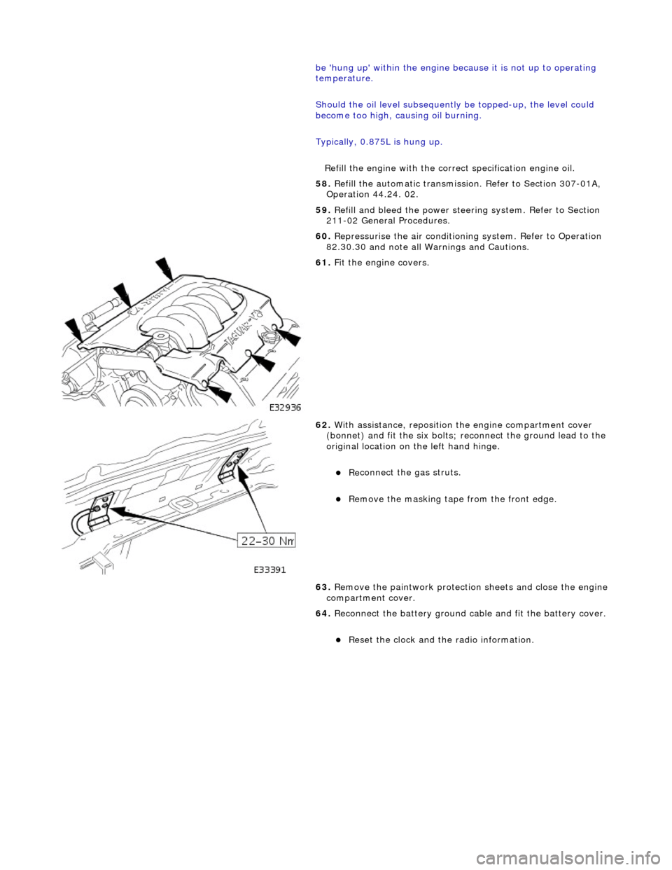
Fit the engine covers.
62
.
With assistance, reposition the engine compartment cover
(bonnet) and fit the si x bolts; reconnect the ground lead to the
original location on the left hand hinge.
Re
connect the gas struts.
R
emove the masking tape from the front edge.
63. Remove the paintwork protection sheets and close the engine
compartment cover.
64. Reconnect the battery ground cable and fit the battery cover.
Re
set the clock and the radio information.
Page 925 of 2490

T
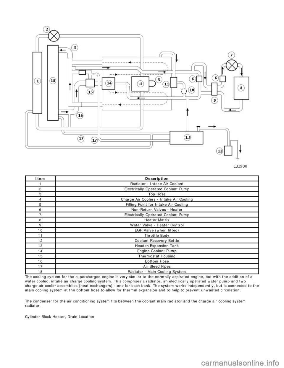
he cooling system for the supercharged engine is very similar
to the normally aspirated engine, but with the addition of a
water cooled, intake air charge cooling system. This comprises a radiator, an electrically operated water pump and two
charge air cooler assemblies (heat exchangers) - one for each bank. The system works independently, but is connected to the
main cooling system at the bottom hose to allow for therma l expansion and to help to prevent unwanted circulation.
The condenser for the air conditioning system fits between th e coolant main radiator and the charge air cooling system
radiator.
Cylinder Block Heater, Drain Location
ItemDe
scription
1Rad
iator - Intake Air Coolant
2Ele
ctrically Operated Coolant Pump
3Top Hose
4Charge Air Coo
lers -
Intake Air Cooling
5Fi
lling Point for Intake Air Cooling
6N
on-Return Valves - Heater
7Ele
ctrically Operated Coolant Pump
8Hea
ter Matrix
9Wate
r Valve - Heater Control
10EGR V
alve (when fitted)
11Thr
ottle Body
12Coolan
t Recovery Bottle
13H
eader/Expansion Tank
14Eng
ine Coolant Pump
15The
rmostat Housing
16Bottom
Hose
17Air Bleed
Pipes
18Rad
iator - Main Cooling System
Page 926 of 2490

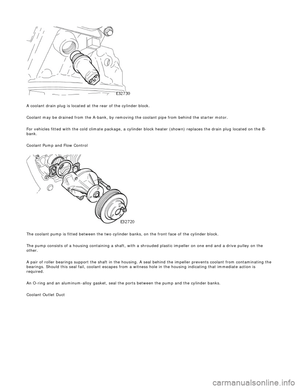
A coola n
t drain plug is located at the rear of the cylinder block.
Coolant may be drained from the A-bank, by removing the coolant pipe from behind the starter motor.
For vehicles fitted with the cold climate package, a cylinder block heater (shown) replaces the drain plug located on the B-
bank.
Coolant Pump and Flow Control
The coolant pump is fitted between the two cylinder banks, on the front face of the cylinder block.
The pump consists of a housing containing a shaft, with a sh rouded plastic impeller on one end and a drive pulley on the
other.
A pair of roller bearings support the shaft in the housing. A seal behind the impeller prevents coolant from contaminating the
bearings. Should this seal fail, coolant escapes from a witness hole in the housin g indicating that immediate action is
required.
An O-ring and an aluminum-alloy gasket, seal the ports between the pump and the cylinder banks.
Coolant Outlet Duct
Page 928 of 2490

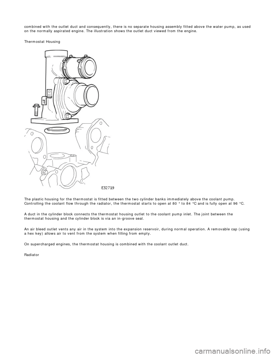
combin
ed with the outlet duct and consequently, there is no separate housin
g assembly fitted above the water pump, as used
on the normally aspirated engine. The illustration shows the outlet duct viewed from the engine.
Thermostat Housing
The plastic housing for the thermostat is fitted between th e two cylinder banks immediately above the coolant pump.
Controlling the coolant flow through the radiator, the thermostat starts to open at 80 ° to 84 °C and is fully open at 96 °C.
A duct in the cylinder block connects the thermostat housing outlet to the coolant pump inlet. The joint between the
thermostat housing and the cylinder block is via an in-groove seal.
An air bleed outlet vents an y air in the system into the expansion reservoir, durin
g normal operation. A removable cap (usin g
a hex key) allows air to vent from the system when filling from empty.
On supercharged engines, the thermostat housin g is combined with the coolant outlet duct.
Radiator