Cruise control JAGUAR X308 1998 2.G Owner's Manual
[x] Cancel search | Manufacturer: JAGUAR, Model Year: 1998, Model line: X308, Model: JAGUAR X308 1998 2.GPages: 2490, PDF Size: 69.81 MB
Page 1751 of 2490

R
EPAIR the high resistance circui
t. For additional information, refer to the wiring diagrams. CLEAR
the DTC. TEST the system for normal operation.
No GO to F10
.
F10: CHECK
THE BRAKE CANCEL SWITCH TO CRUISE CO
NTROL SWITCH TO ECM CIRCUIT FOR SHORT TO HIGH
VOLTAGE
R
econnect the battery negative terminal.
1
Turn the ignition swi
tch to the ON
position.
2
M
easure the voltage between AC24, pin 03 (WU) and GROUND.
3
Is th
e voltage greater than 3 volts?
Yes REPAIR the short circuit. For addi tional information, refer to the wiring diagrams. CLEAR the DTC.
TEST the system for normal operation.
No GO to F11
.
F11: CHECK
THE BRAKE CANCEL SWITCH TO CRUISE
CONTROL SWITCH TO ECM CIRCUIT FOR SHORT TO
GROUND
Turn the ignition swi
tch to the
OFF position.
1
Meas
ure the resistance between AC24, pin 03 (WU) and GROUND.
2
Is
the resistance less than 10,000 ohms?
Yes REPAIR the short circuit. For addi tional information, refer to the wiring diagrams. CLEAR the DTC.
TEST the system for normal operation.
No GO to F12
.
F12: CHECK
THE BRAKE CANCEL SWITCH
IGNITION SWITCHED POWER SUPPLY
Turn the ignition swi
tch to the ON
position.
1
M
easure the voltage between AC24, pin 03 (WU) and GROUND.
2
Is th
e voltage less than 10 volts?
Yes REPAIR the circuit between the brake cancel sw itch and the ignition switch. For additional
information, refer to the wiring diagrams. CLEAR the DTC. TEST the system for normal operation.
No GO to F13
.
F13: CHECK
THE BRAKE CA
NCEL SWITCH OPERATION
Me
asure the resistance between AC24, pins 02 and 03.
1
O
perate the brake pedal up and down.
2
Doe
s the resistance switch between open circuit and continuity as the pedal is operated?
Yes Recheck the DTCs. Failure of other cruise contro l circuits will set other DTCs, indicating the
component at fault.
No INSTALL a new brake cancel switch. CLEAR the DT C. TEST the system for normal operation.
Page 1976 of 2490

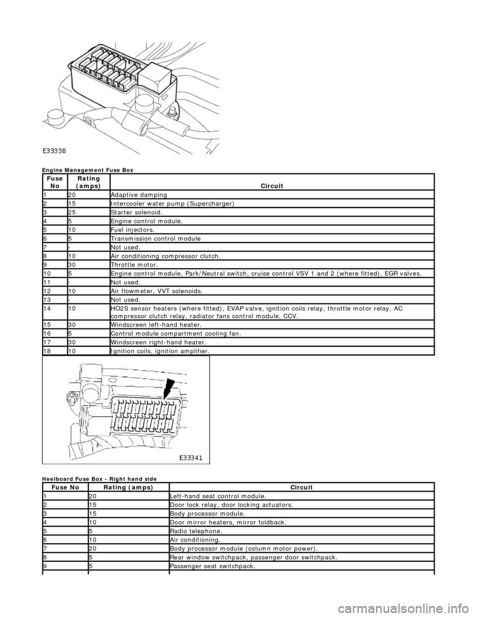
Engine Management Fuse Box
Heelboard Fuse Box - Right hand side
Fuse NoRating
(amps)Circuit
120Adaptive damping
215Intercooler water pump (Supercharger)
325Starter solenoid.
45Engine control module.
510Fuel injectors.
65Transmission control module
7-Not used.
810Air conditioning compressor clutch.
930Throttle motor.
105Engine control module, Park/Neutr al switch, cruise control VSV 1 and 2 (where fitted), EGR valves.
11-Not used.
1210Air flowmeter, VVT solenoids.
13-Not used.
1410HO2S sensor heaters (where fitted ), EVAP valve, ignition coils relay, throttle motor relay, AC
compressor clutch relay, radi ator fans control module, CCV.
1530Windscreen left-hand heater.
165Control module compartment cooling fan.
1730Windscreen right-hand heater.
1810Ignition coils, ignition amplifier.
Fuse NoRating (amps)Circuit
120Left-hand seat control module.
215Door lock relay, door locking actuators.
315Body processor module.
410Door mirror heaters, mirror foldback.
55Radio telephone.
610Air conditioning.
720Body processor module (column motor power).
85Rear window switchpack, passenger door switchpack.
95Passenger seat switchpack.
Page 1977 of 2490

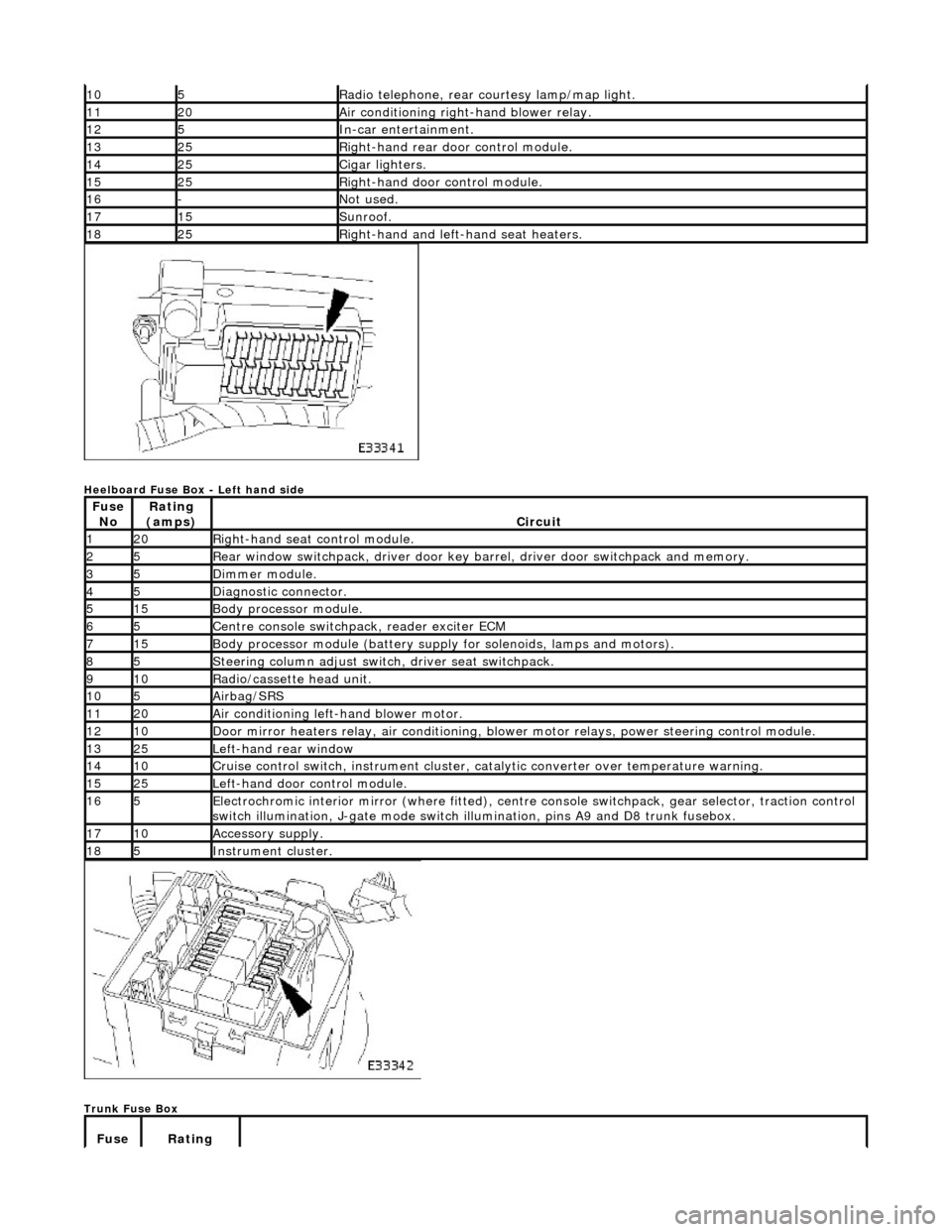
Heelboard Fuse Box - Left hand side
Trunk Fuse Box
105Radio telephone, rear courtesy lamp/map light.
1120Air conditioning right-hand blower relay.
125In-car entertainment.
1325Right-hand rear door control module.
1425Cigar lighters.
1525Right-hand door control module.
16-Not used.
1715Sunroof.
1825Right-hand and left-hand seat heaters.
Fuse NoRating
(amps)Circuit
120Right-hand seat control module.
25Rear window switchpack, driver door key ba rrel, driver door switchpack and memory.
35Dimmer module.
45Diagnostic connector.
515Body processor module.
65Centre console switchpack, reader exciter ECM
715Body processor module (battery supply for solenoids, lamps and motors).
85Steering column adjust switch, driver seat switchpack.
910Radio/cassette head unit.
105Airbag/SRS
1120Air conditioning left-hand blower motor.
1210Door mirror heaters relay, air conditioning, blow er motor relays, power steering control module.
1325Left-hand rear window
1410Cruise control switch, instrument cluster, catalytic converter over temperature warning.
1525Left-hand door control module.
165Electrochromic interior mirror (where fitted), centre console switchpack, gear selector, traction control
switch illumination, J-gate mode switch illumination, pins A9 and D8 trunk fusebox.
1710Accessory supply.
185Instrument cluster.
Fuse Rating
Page 2219 of 2490

Instrument Panel and Console - Instrument Panel and Instrument Panel
Console
Description and Operation
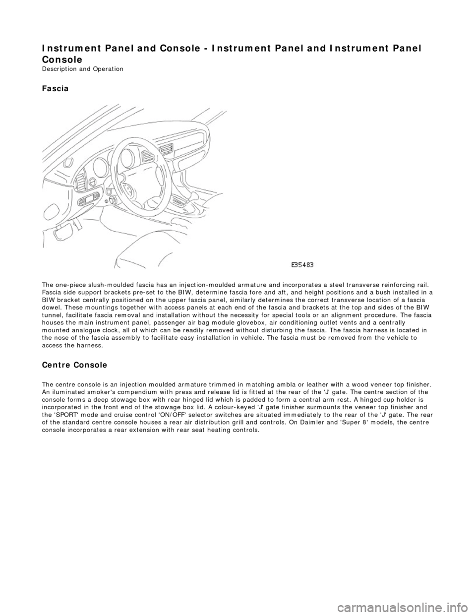
Fascia
The one-piece slush-moulded fascia has an injection-moulded ar mature and incorporates a steel transverse reinforcing rail.
Fascia side support brackets pre-set to th e BIW, determine fascia fore and aft, and height position s and a bush installed in a
BIW bracket centrally positioned on the upper fascia panel, similarly determines the correct transverse location of a fascia
dowel. These mountings together with access panels at each en d of the fascia and brackets at the top and sides of the BIW
tunnel, facilitate fascia removal and instal lation without the necessity for special tools or an alignment procedure. The fasci a
houses the main instrument panel, pass enger air bag module glovebox, air conditioning outlet vents and a centrally
mounted analogue clock, all of which can be readily removed wi thout disturbing the fascia. The fascia harness is located in
the nose of the fascia assembly to facilitate easy installati on in vehicle. The fascia must be removed from the vehicle to
access the harness.
Centre Console
The centre console is an injection moulded armature trimmed in matching ambla or leather with a wood veneer top finisher.
An iluminated smoker's compendium with pr ess and release lid is fitted at the rear of the 'J' gate. The centre section of the
console forms a deep stowage box with rear hinged lid which is padded to form a central arm rest. A hinged cup holder is
incorporated in the front end of the stowage box lid. A colour-keyed 'J' gate finisher surmounts the veneer top finisher and
the 'SPORT' mode and cruise control 'ON/OFF' selector switches are situated immediately to the rear of the 'J' gate. The rear
of the standard centre console houses a re ar air distribution grill and controls. On Daimler and 'Super 8' models, the centre
console incorporates a rear extensio n with rear seat heating controls.
Page 2229 of 2490

Instrument Panel and Console - Floor Console Finish Panel
Removal and Installation
Removal
1. Apply handbrake and turn ignition key to II.
2. Depress brake pedal, move gear selector to position N and turn
ignition key to O.
3. Remove battery cover and di sconnect cable from earth
terminal. Refer to Section 86.15.19.
4. Remove 'J 'gate finisher. Refer to 76.25.24.
5. Slacken and remove the two nuts and two screws securing
the retaining panel.
6. Position retaining panel for access, disconnect SPORT mode
and cruise control ON/OFF swit ch multiplugs and remove
retaining panel complete with switches.
7. Remove and discard bushes from retaining plate.
8. Carefully withdraw veneer pane l, releasing front locating
tongue from upper slot in comsole.
Page 2230 of 2490

Installation
1. Position veneer panel on consol e, ensuring that front tongue
locates correctly in console upper slot.
2. Fit and fully seat new bush es in retaining panel.
3. Position retaining panel complete with SPORT mode and cruise
control ON/OFF switches for ac cess and connect multiplugs.
4. fully seat retaining panel and fi t and tighten securing nuts and
screws.
5. Fit 'J' gate surround finisher. Refer to 76.25.24.
6. Move gear selector to position P.
7. Connect cable to battery earth te rminal and fit battery cover.
Refer to Section 86.15.15.
Page 2231 of 2490

In
strument Panel and Console - Floor Console Finish Panel Bracket
Rem
oval and Installation
Remov
al
Installation
1.
Remove 'J' gate finisher. Refer to 76.25.24.
2.
Slacken and remove the two front nuts and two rear screws
securing the retaining panel.
3.
Position retaining panel for access, disconnect SPORT mode and
cruise control ON/OFF switch multiplugs and remove retaining
panel complete with switches.
4. Remove switches from retaining panel.
5.
Remove and discard bushes from retaining panel.
1. Fit and fully seat new bushes in retaining panel.
2. Fit and fully seat SPORT mode and cruise control ON/OFF
switches in retaining panel.
3. Position retaining panel for access and connect SPORT mode and
cruise control ON/OFF switch multiplugs.
4. Fully seat retaining panel and fit and tighten securing nuts and
screws.
5. Fit 'J' gate surround finisher. Refer to 76.25.24.