height JAGUAR X308 1998 2.G Workshop Manual
[x] Cancel search | Manufacturer: JAGUAR, Model Year: 1998, Model line: X308, Model: JAGUAR X308 1998 2.GPages: 2490, PDF Size: 69.81 MB
Page 33 of 2490

501‐17: Roof Open
ing
Panel
Description and Operation
Roof Opening Panel
General Procedures
Motor Synchronization (76.82.48)
Roof Opening Panel Alignment
Removal and Installation
Roof Opening Panel (76.82.05)
Roof Opening Panel Frame (76.82.01)
Roof Opening Panel Module (86.76.07)
Roof Opening Panel Motor (86.76.01)
Roof Opening Panel Shie
ld (76.82.06)
Roof Opening Panel Trim
Roof Opening Panel Weatherstrip (76.82.15)
501‐19: Bumpers
Specification
Description and Operation
Bumpers
Removal and Installation
Front Bumper (76.22.08)
Front Bumper and Bumper Cover (76.22.08)
Front Bumper Cover (76.22.78)
Front Bumper Isolator (76.22.31)
Rear Bumper (76.22.27) (76.22.52)
Rear Bumper Co
ver (76.22.74) (76.22.77)
Rear Bumper Isolator (76.22.70)
501‐20A : Safety Belt System
Specification
Description and Operation
Safety Belt System
Removal and Installation
Front Safety Belt Retractor (76.73.10)
Rear Safety Belt Retractor (76.73.18)
Safety Belt Shoulder Height Adjuster (76.73.12)
Page 58 of 2490
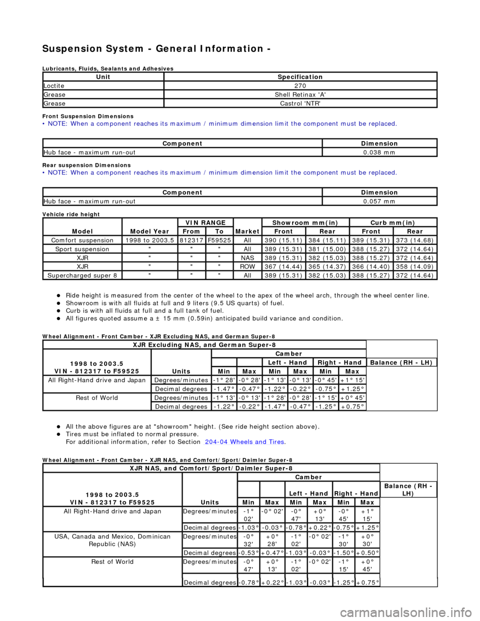
Suspension System - General Informatio
n -
Lubric
ants, Fluids, Sealants and Adhesives
Front Suspension Dimensions
• NO
TE: When a component reaches its maximum / minimum dimension limit the component must be replaced.
Rear sus
p
ension Dimensions
•
NO
TE: When a component reaches its maximum / minimum dimension limit the component must be replaced.
Vehicle ride
height
R i
de height is measured from
the center of the wheel to the apex of the wheel arch, through the wheel center line.
Showroom is with a
ll fluids at full an
d 9 liters (9.5 US quarts) of fuel.
Curb is
with all fluids at full and a full tank of fuel.
All f
i
gures quoted assume a ±
15 mm (0.59in) anticipated bu ild variance and condition.
Whee
l Alignment - Front Camber - XJR Excluding NAS, and German Super-8
Al l the above fi
gures
are at "showroom" height. (See ride height section above).
Tires must be infl
ated
to normal pressure.
For additional informat ion, refer to Section 204
-04
Wheels and Tires
.
Whe
e
l Alignment - Front Camber - XJR NAS, and Comfort/Sport/Daimler Super-8
UnitSp
ecification
Loctite27
0
Greas eShell Retin a
x 'A'
Greas
eCastro l 'NT
R'
Com
p
onent
Di
mensi
on
Hub face
-
maximum run-out
0.
03
8 mm
Com
p
onent
Di
mensi
on
Hub face
-
maximum run-out
0.
05
7 mm
Mod
e
l
Mod
e
l Year
V
I
N RANGE
Mark
et
Sh
owroom mm(in)
Curb mm(i
n)
FromToFron
t
RearFr
on
t
Rear
Com
f
ort suspension
1
998
to 2003.5
8
123
17
F
595
25
All3
90 (
15.11)
3
84 (
15.11)
3
89 (
15.31)
3
73 (
14.68)
Sport su
spe
nsion
"""All3
89 (
15.31)
3
81 (
15.00)
3
88 (
15.27)
3
72 (
14.64)
XJR"""NAS3
89 (
15.31)
3
82 (
15.03)
3
88 (
15.27)
3
72 (
14.64)
XJR"""RO
W367 (
14.44)
3
65 (
14.37)
3
66 (
14.40)
3
58 (
14.09)
Supercharged super 8"""All3
89 (
15.31)
3
82 (
15.03)
3
88 (
15.27)
3
72 (
14.64)
XJR
Excluding NAS, and German Super-8
1998 to
2003.5
VIN - 812317 to F59525
Units
Cambe r
Left
- Hand
Rig
h
t - Hand
Bal
a
nce (RH - LH)
MinMaxMinMaxMinMax
All Right-Hand driv
e and JapanDegrees
/minutes
-
1
° 28'
-0
°
28'
-
1
° 13'
-
0
° 13'
-0
° 45'+1 °
15'
Decimal degrees-1.
4
7°
-0
.4
7°
-1
.2
2°
-0.
2
2°
-0
.7
5°
+1
.25
°
R
e
st of World
De
grees
/minutes
-
1
° 13'
-0
°
13'
-
1
° 28'
-
0
° 28'
-1
° 15'+0 °
45'
Decimal degrees-1.
2
2°
-0
.2
2°
-1
.4
7°
-0.
4
7°
-1
.2
5°
+0
.75
°
XJR
NAS, and Comfort/Sport/Daimler Super-8
1
998 to
2003.5
VIN - 812317 to F59525
Units
Cambe r
Left
- Hand
Rig
h
t - Hand
Bal
a
nce (RH -
LH)
MinMaxMinMaxMinMax
All Right-Hand drive and JapanDegrees
/minutes
-1°
02'-0
° 02'
-0°
47'
+0°
13'
-0° 45'+1°
15'
Decimal degrees-1.0
3°
-0.0
3°
-0.7
8°
+0.22
°
-0.7
5°
+1.25
°
USA, Canada an
d Mexico,
Dominican
Republic (NAS)
De grees
/minutes
-0°
32 '+0 °
28'
-1 °
02'
-0 °
02'
-1°
30 '+0 °
30'
Decimal degrees-0. 5
3°
+0
.47
°
-1
.0
3°
-0
.0
3°
-1.
5
0°
+0
.50
°
R
e
st of World
De
grees
/minutes
-0°
47 '+0 °
13'
-1 °
02'
-0 °
02'
-1°
15 '+0 °
45'
Decimal degrees-0. 7
8°
+0
.22
°
-1
.0
3°
-0
.0
3°
-1.
2
5°
+0
.75
°
Page 59 of 2490
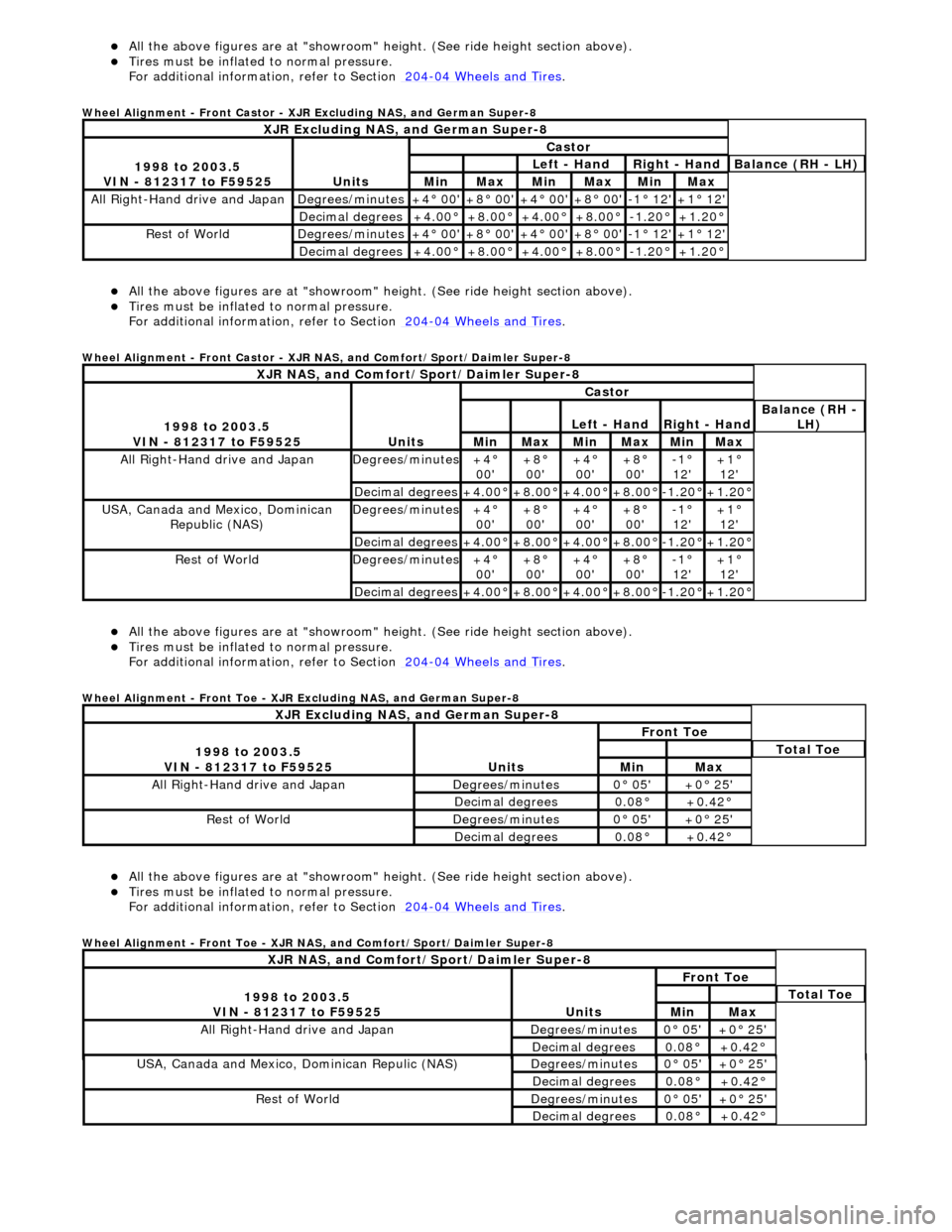
Al
l the above figures
are at "showroom" height. (See ride height section above).
Ti
res must be inflated
to normal pressure.
For additional informat ion, refer to Section 204
-0
4 Wheels and Tires
.
Whe
el Alignment - Front Castor - XJR Excluding NAS, and German Super-8
Al
l the above figures
are at "showroom" height. (See ride height section above).
Ti
res must be inflated
to normal pressure.
For additional informat ion, refer to Section 204
-0
4 Wheels and Tires
.
Whe
el Alignment - Front Castor - XJR NAS, and Comfort/Sport/Daimler Super-8
Al
l the above figures
are at "showroom" height. (See ride height section above).
Ti
res must be inflated
to normal pressure.
For additional informat ion, refer to Section 204
-0
4 Wheels and Tires
.
Whe
el Alignment - Front Toe - XJR Excluding NAS, and German Super-8
Al
l the above figures
are at "showroom" height. (See ride height section above).
Ti
res must be inflated
to normal pressure.
For additional informat ion, refer to Section 204
-0
4 Wheels and Tires
.
Whe
el Alignment - Front Toe - XJR NAS, and Comfort/Sport/Daimler Super-8
XJR
Excluding NAS, and German Super-8
1
998 to 2003.5
VIN - 812317 to F59525
Units
Castor
Le
ft - Hand
Rig
ht - Hand
Bal
ance (RH - LH)
MinMaxMinMaxMinMax
All Right
-Hand drive and Japan
De
grees/minutes
+4
° 00'
+8
° 00'
+4
° 00'
+8
° 00'
-1
° 12'
+1
° 12'
Decimal degrees+4
.00°
+8
.00°
+4
.00°
+8
.00°
-1.
20°
+1
.20°
R
est of World
De
grees/minutes
+4
° 00'
+8
° 00'
+4
° 00'
+8
° 00'
-1
° 12'
+1
° 12'
Decimal degrees+4
.00°
+8
.00°
+4
.00°
+8
.00°
-1.
20°
+1
.20°
XJR
NAS, and Comfort/Sport/Daimler Super-8
1
998 to 2003.5
VIN - 812317 to F59525
Units
Castor
Le
ft - Hand
Rig
ht - Hand
Bal
ance (RH -
LH)
MinMaxMinMaxMinMax
All Right
-Hand drive and Japan
De
grees/minutes
+4
°
00'
+8
°
00'
+4
°
00'
+8
°
00'
-1
°
12'
+1
°
12'
Decimal degrees+4
.00°
+8
.00°
+4
.00°
+8
.00°
-1.
20°
+1
.20°
USA, Canada an
d Mexico, Dominican
Republic (NAS)
De
grees/minutes
+4
°
00'
+8
°
00'
+4
°
00'
+8
°
00'
-1
°
12'
+1
°
12'
Decimal degrees+4
.00°
+8
.00°
+4
.00°
+8
.00°
-1.
20°
+1
.20°
R
est of World
De
grees/minutes
+4
°
00'
+8
°
00'
+4
°
00'
+8
°
00'
-1
°
12'
+1
°
12'
Decimal degrees+4
.00°
+8
.00°
+4
.00°
+8
.00°
-1.
20°
+1
.20°
XJR
Excluding NAS, and German Super-8
1
998 to 2003.5
VIN - 812317 to F59525
Units
Fr
ont Toe
To
tal Toe
MinMax
All Right-Hand driv
e and Japan
De
grees/minutes
0
° 05'
+0
° 25'
Decimal degrees0.
08°
+0
.42°
R
est of World
De
grees/minutes
0
° 05'
+0
° 25'
Decimal degrees0.
08°
+0
.42°
XJR
NAS, and Comfort/Sport/Daimler Super-8
1
998 to 2003.5
VIN - 812317 to F59525
Units
Fr
ont Toe
To
tal Toe
MinMax
All Right-Hand driv
e and Japan
De
grees/minutes
0
° 05'
+0
° 25'
Decimal degrees0.
08°
+0
.42°
USA, Canada an
d Mexico
, Dominican Repulic (NAS)
De
grees/minutes
0
° 05'
+0
° 25'
Decimal degrees0.
08°
+0
.42°
R
est of World
De
grees/minutes
0
° 05'
+0
° 25'
Decimal degrees0.
08°
+0
.42°
Page 60 of 2490
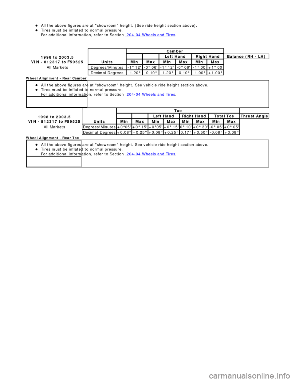
All the above fi
gures
are at "showroom" height. (See ride height section above).
Tires must be infl
ated
to normal pressure.
For additional informat ion, refer to Section 204
-04
Wheels and Tires
.
Wh
eel Alignment - Rear Camber
All the above figu res
are at "s
howroom" height. See vehicle ride height section above.
Tires must be infl
ated
to normal pressure.
For additional informat ion, refer to Section 204
-04
Wheels and Tires
.
W
h
eel Alignment - Rear Toe
All the above figu res
are at "s
howroom" height. See vehicle ride height section above.
Tires must be infl
ated
to normal pressure.
For additional informat ion, refer to Section 204
-04
Wheels and Tires
.
1 998 to
2003.5
VIN - 812317 to F59525
Units
Cambe r
Left
Hand
Rig
h
t Hand
Bal
a
nce (RH - LH)
Min MaxMin MaxMinMax
All MarketsDe
grees
/Minutes
-
1
° 12'
-0
° 06'-1° 12'-0
° 06'
-1
°
00
+1
°
00
De
ci
mal Degrees
-1.
2
0°
-0
.1
0°
-1.
2
0°
-0.
1
0°
-1.
0
0°
+1
.00
°
1
998 to
2003.5
VIN - 812317 to F59525
Units
To e
Left
Hand
Rig
h
t Hand
To
t
al Toe
Thr
u
st Angle
MinMaxMinMaxMin MaxMin Max
All MarketsDe
grees
/Minutes
+0
°
05'
+0
° 15'+0°
05'
+0
° 15'0°
10'
+0
° 30'-0° 05'+0 °
05'
De
ci
mal Degrees
+0
.08
°
+0
.25
°
+0
.08
°
+0
.25
°
0.
17
°
+0
.50
°
-0.
0
8°
+0
.08
°
Page 222 of 2490
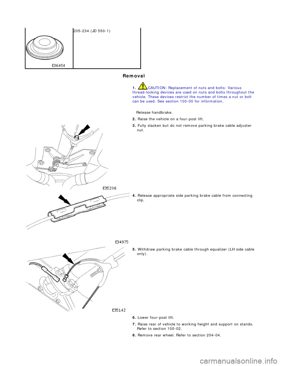
Remova
l
2
05-2
34 (JD 550-1)
1. CAUTION: Replacement of nuts and bolts: Various
thread-locking devices are used on nuts and bolts throughout the
vehicle. These devices restrict the number of times a nut or bolt
can be used. See section 100-00 for information.
Release handbrake.
2. Ra
ise the vehicle on a four-post lift.
3. Fully slacken bu
t do not remove parking brake cable adjuster
nut.
4. Relea s
e appropriate side parkin
g brake cable from connecting
clip.
5. With draw parkin
g brake cable th
rough equalizer (LH side cable
only).
6. Lower four-post lift.
7. Raise rear of vehicle to workin g height and support on stands.
Refer to section 100-02.
8. Remove rear wheel. Refer to section 204-04.
Page 238 of 2490

clip
.
5. With draw parkin
g brake cable th
rough equalizer (LH side cable
only).
6. Lower four-post lift.
7. Raise rear of vehicle to workin g height and support on stands.
Refer to section 100-02.
8. Remove rear wheel. Refer to section 204-04.
9. Posit i
on special tool (204-1
95) on hub studs and install
securing nuts.
10 . Slac
ken but do not remove hub to axle shaft securing nut.
11. Remove nuts and withdraw special tool (204-195) from hub.
12. Remove rear brake disc. Refer to 70.10.13.
13. Remove parking brake shoe s. Refer to 70.40.05.
14. Remove wheel speed sensor.
Page 249 of 2490

cli
p.
5. With
draw parking brake cable th
rough equalizer (LH side cable
only).
6. Lower four-post lift.
7. Raise rear of vehicle to workin g height and support on stands.
Refer to section 100-02.
8. Remove rear wheel. Refer to section 204-04.
9. Posit
ion special tool (204-1
95) on hub studs and install
securing nuts.
10
.
Slacken but do not remove hub to axle shaft securing nut.
11. Remove securing nuts from stud s and withdraw special tool
(204-195) from hub.
12. Remove rear brake disc. Refer to 70.10.13.
13. Remove parking brake shoe s. Refer to 70.40.05.
14. Remove wheel speed sensor.
Page 273 of 2490
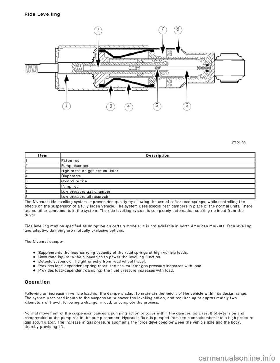
The
Nivomat ride levelling system improves ride quality by al
lowing the use of softer road springs, while controlling the
effects on the suspension of a fully laden vehicle. The system uses special rear dampers in place of the normal units. There
are no other components in th e system. The ride levelling system is comple tely automatic, requiring no input from the
driver.
Ride levelling may be specified as an opti on on certain models; it is not available in north American markets. Ride levelling
and adaptive damping are mu tually exclusive options.
The Nivomat damper:
Su
pplements the load-carrying capacity of th
e road springs at high vehicle loads.
Uses road inputs to the
suspension to power the levelling function.
De
tects suspension height dire
ctly from road wheel travel.
Provi
des load-dependent spring rates; the ac
cumulator gas pressure increases with load.
Pr
ovides load-dependent damping; the fluid pressure increases with load.
Op
eration
F
ollowing an increase in vehicle loading,
the dampers adapt to maintain the height of the vehicle within its design range.
The system uses road inputs to the suspension to power the levelling action, and requires up to approximately two
kilometers of travel, following a change in load, to complete the process.
Normal movement of the suspension caus es a pumping action to occur within the damper, as a result of extension and
compression of the pump rod in the pump chamber. Hydraulic fluid is pumped from the pump cham ber into a high pressure
gas accumulator. The increase in gas pressure augments the force developed between th e vehicle axle and the body,
thereby providing lift.
It
em
De
scription
1Pi
ston rod
2Pum
p chamber
3High
pressure
gas accumulator
4Diaphragm
5Co
ntrol orifice
6Pump rod
7Low pressure gas ch
amber
8Low pressure oil
reservoir
Ride Levelling
Page 274 of 2490
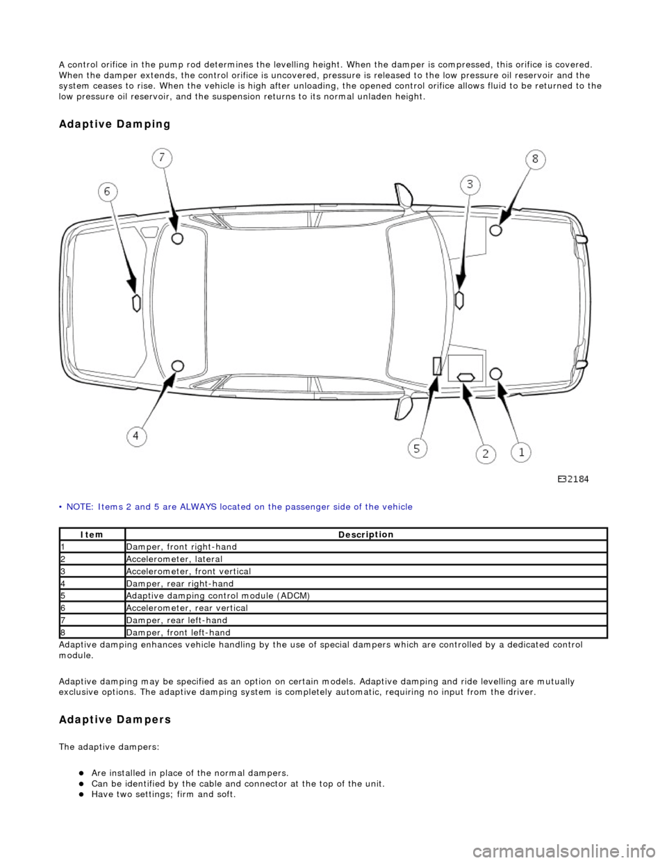
A c
ontrol orifice in the pump rod determines the levelling height. When the damper is compressed, this orifice is covered.
When the damper extends, the control orif ice is uncovered, pressure is released to the low pressure oil reservoir and the
system ceases to rise. When the vehicle is high after unloading, the opened control or ifice allows fluid to be returned to the
low pressure oil reservoir, and the suspensi on returns to its normal unladen height.
Ad
aptive Damping
•
NOTE: Items 2 and 5 are ALWAYS located
on the passenger side of the vehicle
Adaptive damping enhances vehicle handli ng by the use of special dampers which are controlled by a dedicated control
module.
Adaptive damping may be specified as an option on certai n models. Adaptive damping and ride levelling are mutually
exclusive options. The adaptive damping system is completely automatic, requiring no input from the driver.
A d
aptive Dampers
The adaptiv
e dampers:
Are inst
alled in place of the normal dampers.
Can be identified
by the cable and connector at the top of the unit.
Have two settings; fi
rm and so
ft.
It
e
m
De
scr
iption
1Dam
p
er, front right-hand
2Accel
e
rometer, lateral
3Accel
e
rometer,
front vertical
4D
a
mper, rear right-hand
5Adaptive dampin
g control module (A
DCM)
6Accel
e
rometer, rear vertical
7D
amper, rear l
eft-hand
8Dam
p
er, front left-hand
Page 908 of 2490

3. Disconnect the brake servo hose.
60. Fit engine rear lifting eyes (303 - 536).
61. Traverse the hoist to the engine compartment and lower it to
working height.
62. Fit lifting chains to the hoist and connect to each engine
lifting eye. Use longer chains to the rear lifting eyes to allow
the engine to tilt rearwards wh en removing from the vehicle.
63. Remove the engine front mounting nuts.
64. Raise the ramp.
65. Disconnect the transmission connector.
1. Release the lever lock on the transmission harness
multi-plug.
2. Disconnect the connector.
66. Disconnect the transmission selector cable.