boot JAGUAR X308 1998 2.G Owner's Manual
[x] Cancel search | Manufacturer: JAGUAR, Model Year: 1998, Model line: X308, Model: JAGUAR X308 1998 2.GPages: 2490, PDF Size: 69.81 MB
Page 1199 of 2490
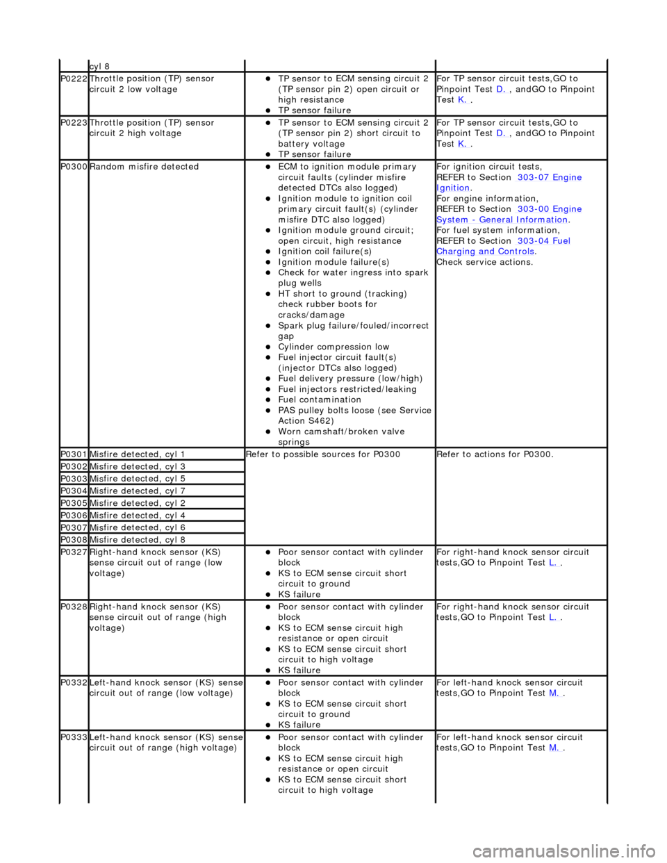
cyl 8
P0222Thro
ttle position (TP) sensor
circuit 2 low voltage
TP se
nsor to ECM sensing circuit 2
(TP sensor pin 2) open circuit or
high resistance
TP sensor
failure
F
or TP sensor circ
uit tests,GO to
Pinpoint Test D.
, andG
O to Pinpoint
Test K.
.
P0223Thro
ttle position (TP) sensor
circuit 2 high voltage
TP se
nsor to ECM sensing circuit 2
(TP sensor pin 2) short circuit to
battery voltage
TP sensor
failure
F
or TP sensor circ
uit tests,GO to
Pinpoint Test D.
, andG
O to Pinpoint
Test K.
.
P0300Ran
dom misfire detected
ECM to
ignition module primary
circuit faults (cylinder misfire
detected DTCs also logged)
Igni
tion module to ignition coil
primary circuit fault(s) (cylinder
misfire DTC also logged)
Ignition modu
le ground circuit;
open circuit, hi gh resistance
Ignition coil
failure(s)
Ignition modul
e failure(s)
Check f
or water ingress into spark
plug wells
HT sho
rt to ground (tracking)
check rubber boots for
cracks/damage
Spark plug
failure/fouled/incorrect
gap
Cy
linder compression low
F
uel injector circuit fault(s)
(injector DTCs also logged)
F
uel delivery pressure (low/high)
F
uel injectors restricted/leaking
Fuel contamination
P
AS pulley bolts loose (see Service
Action S462)
W
orn camshaft/broken valve
springs
F
or ignition circuit tests,
REFER to Section 303
-07
Engine
Ignition.
F
or engine information,
REFER to Section 303
-00
Engine
Sy
stem
- General
Information
.
F
or fuel system information,
REFER to Section 303
-04
Fuel
Charging and Con
trols
.
Check service
actions.
P0301Mis
fire detected, cyl 1
R
efer to possible sources for P0300
R
efer to actions for P0300.
P0302Mis
fire detected, cyl 3
P0303Mis
fire detected, cyl 5
P0304Mis
fire detected, cyl 7
P0305Mis
fire detected, cyl 2
P0306Mis
fire detected, cyl 4
P0307Mis
fire detected, cyl 6
P0308Mis
fire detected, cyl 8
P0327Right
-hand knock sensor (KS)
sense circuit out of range (low
voltage)
Poor sensor cont
act with cylinder
block
KS to
ECM sense circuit short
circuit to ground
KS fai
lure
F
or right-hand knock sensor circuit
tests,GO to Pinpoint Test L.
.
P0328Right
-hand knock sensor (KS)
sense circuit out of range (high
voltage)
Poor sensor cont
act with cylinder
block
KS to EC
M sense circuit high
resistance or open circuit
KS to
ECM sense circuit short
circuit to high voltage
KS fai
lure
F
or right-hand knock sensor circuit
tests,GO to Pinpoint Test L.
.
P0332Left-hand knock sens
or (KS) sense
circuit out of range (low voltage)
Poor sensor cont
act with cylinder
block
KS to
ECM sense circuit short
circuit to ground
KS fai
lure
F
or left-hand knoc
k sensor circuit
tests,GO to Pinpoint Test M.
.
P0333Left-hand knock sens
or (KS) sense
circuit out of range (high voltage)
Poor sensor cont
act with cylinder
block
KS to EC
M sense circuit high
resistance or open circuit
KS to
ECM sense circuit short
circuit to high voltage
F
or left-hand knoc
k sensor circuit
tests,GO to Pinpoint Test M.
.
Page 1696 of 2490
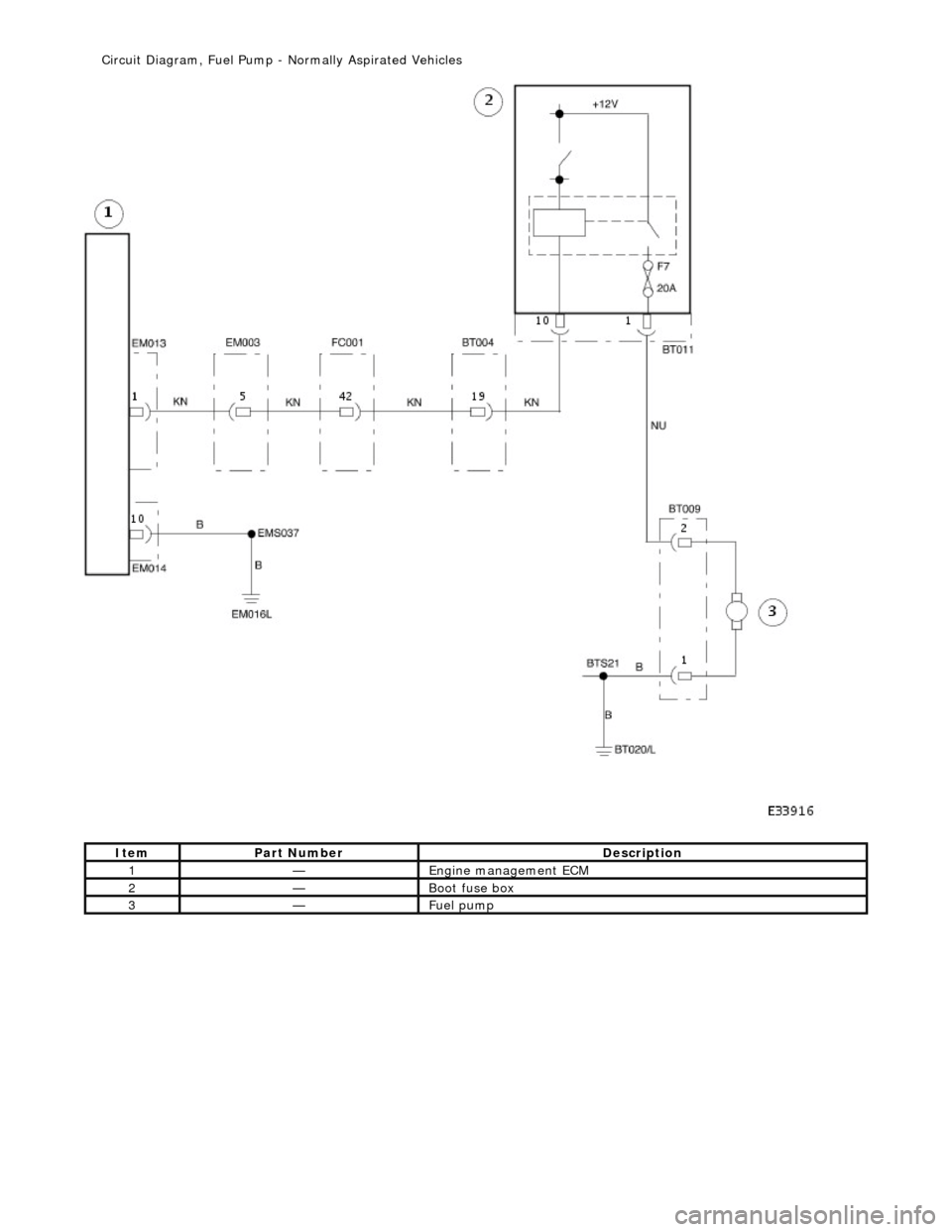
Ite
m
Par
t
Number
De
scr
iption
1—Engine
m
anagement ECM
2—Boot fuse box
3—Fue
l
pump
Ci
rcui
t Diagram, Fuel Pump -
Normally Aspirated Vehicles
Page 1697 of 2490
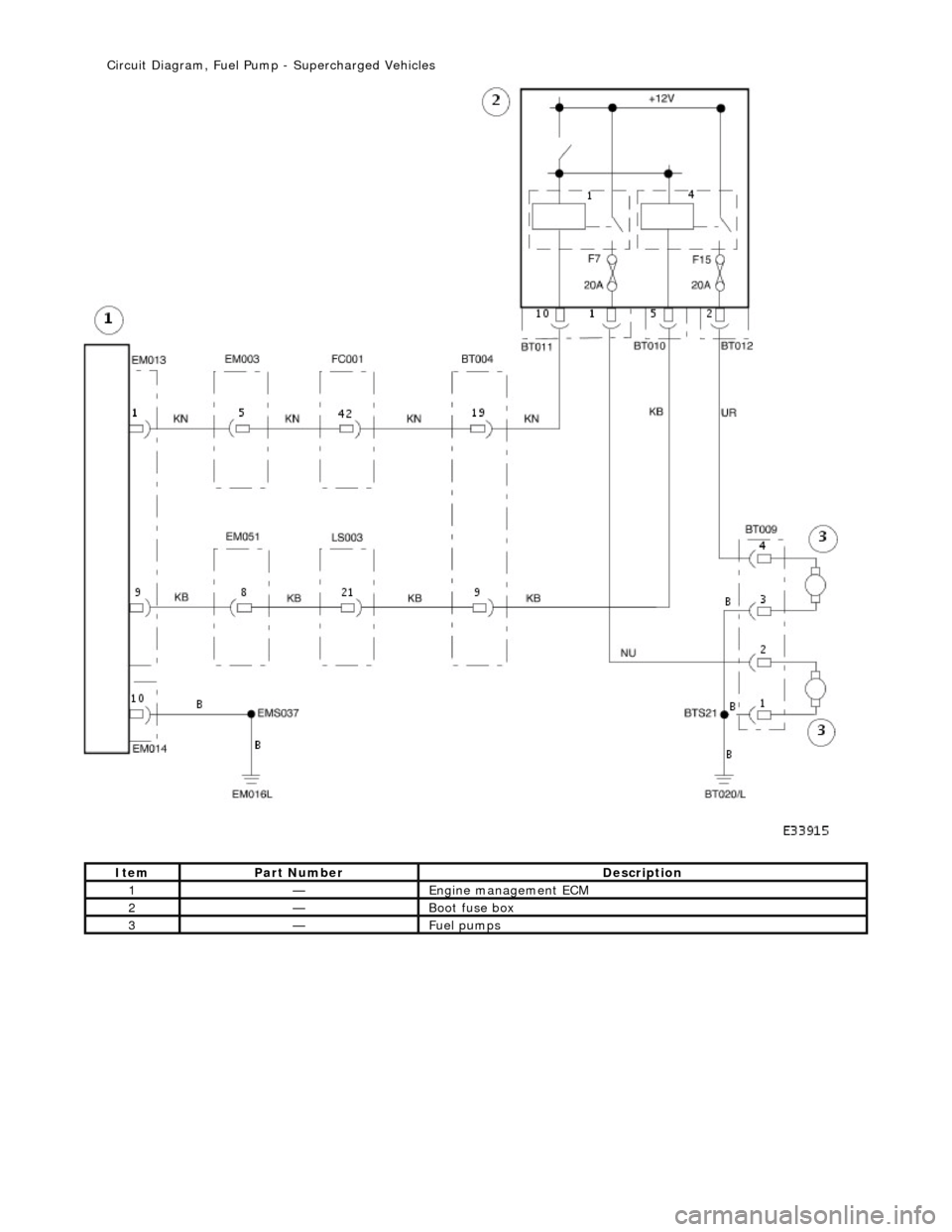
It
em
Par
t Number
De
scription
1—Engine
management ECM
2—Boot fuse box
3—Fue
l pumps
Ci
rcuit Diagram, Fuel Pump
- Supercharged Vehicles
Page 1890 of 2490
Generator and Regulator - Generator4.0L NA V8 - AJ27/3.2L NA V8 - AJ26
Removal and Installation
Removal
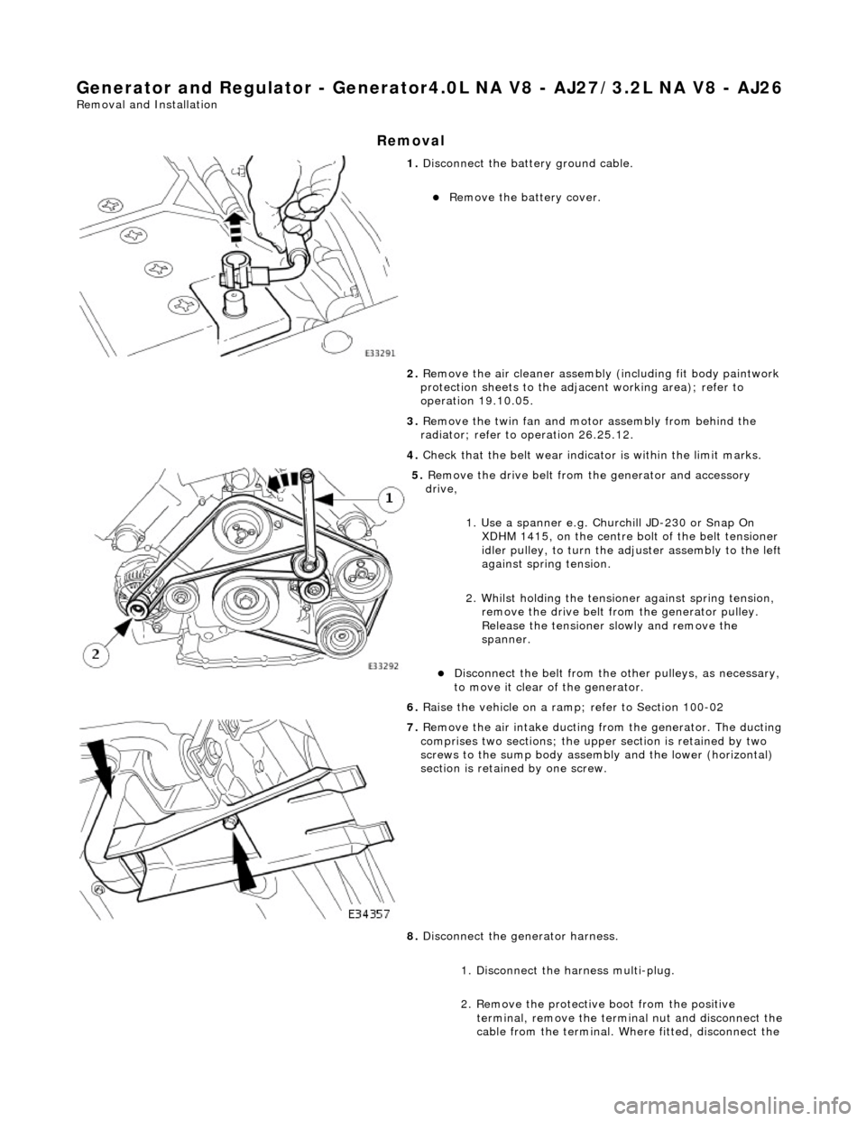
1. Disconnect the batt ery ground cable.
Remove the battery cover.
2. Remove the air cleaner assembly (including fit body paintwork
protection sheets to the adja cent working area); refer to
operation 19.10.05.
3. Remove the twin fan and moto r assembly from behind the
radiator; refer to operation 26.25.12.
4. Check that the belt wear indicator is within the limit marks.
5. Remove the drive belt from the generator and accessory
drive,
1. Use a spanner e.g. Churchill JD-230 or Snap On XDHM 1415, on the centre bo lt of the belt tensioner
idler pulley, to turn the adju ster assembly to the left
against spring tension.
2. Whilst holding the tensioner against spring tension, remove the drive belt from the generator pulley.
Release the tensioner sl owly and remove the
spanner.
Disconnect the belt from the ot her pulleys, as necessary,
to move it clear of the generator.
6. Raise the vehicle on a ramp; refer to Section 100-02
7. Remove the air intake ducting fr om the generator. The ducting
comprises two sections; the upper section is retained by two
screws to the sump body assembly and the lower (horizontal)
section is retained by one screw.
8. Disconnect the generator harness.
1. Disconnect the harness multi-plug.
2. Remove the protective boot from the positive
terminal, remove the termin al nut and disconnect the
cable from the terminal. Where fitted, disconnect the
Page 1893 of 2490
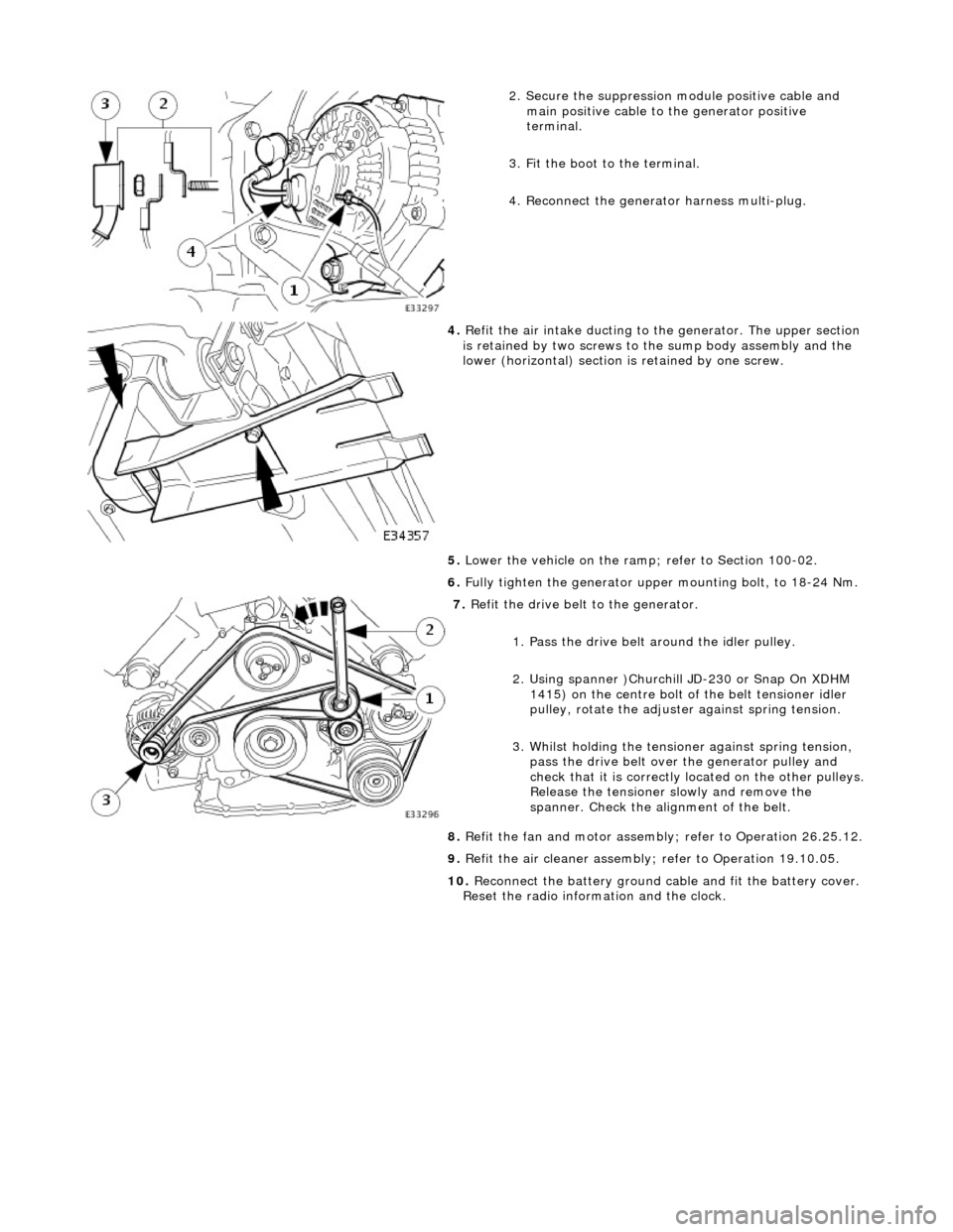
2. Secure the suppression module positive cable and
main positive cable to the generator positive
terminal.
3. Fit the boot to the terminal.
4. Reconnect the generator harness multi-plug.
4. Refit the air intake ducting to the generator. The upper section
is retained by two screws to the sump body assembly and the
lower (horizontal) section is retained by one screw.
5. Lower the vehicle on the ramp ; refer to Section 100-02.
6. Fully tighten the generator upper mounting bolt, to 18-24 Nm.
7. Refit the drive belt to the generator.
1. Pass the drive belt around the idler pulley.
2. Using spanner )Churchill JD-230 or Snap On XDHM 1415) on the centre bolt of the belt tensioner idler
pulley, rotate the adjuster against spring tension.
3. Whilst holding the tensioner against spring tension, pass the drive belt over the generator pulley and
check that it is correctly located on the other pulleys.
Release the tensioner slowly and remove the
spanner. Check the alignment of the belt.
8. Refit the fan and motor assembly ; refer to Operation 26.25.12.
9. Refit the air cleaner assembly; refer to Operation 19.10.05.
10. Reconnect the battery ground cable and fit the battery cover.
Reset the radio inform ation and the clock.
Page 1895 of 2490
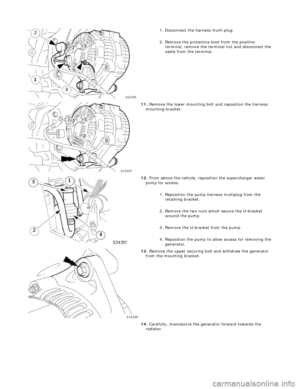
1. Disconnect the harness multi-plug.
2. Remove the protective boot from the positive
terminal, remove the termin al nut and disconnect the
cable from the terminal.
11. Remove the lower mounting bolt and reposition the harness
mounting bracket.
12. From above the vehicle, reposi tion the supercharger water
pump for access.
1. Reposition the pump harness multiplug from the
retaining bracket.
2. Remove the two nuts which secure the U-bracket around the pump.
3. Remove the U-bracket from the pump.
4. Reposition the pump to al low access for removing the
generator.
13. Remove the upper securing bolt and withdraw the generator
from the mounting bracket.
14. Carefully, manoeuvre the ge nerator forward towards the
radiator.
Page 1897 of 2490
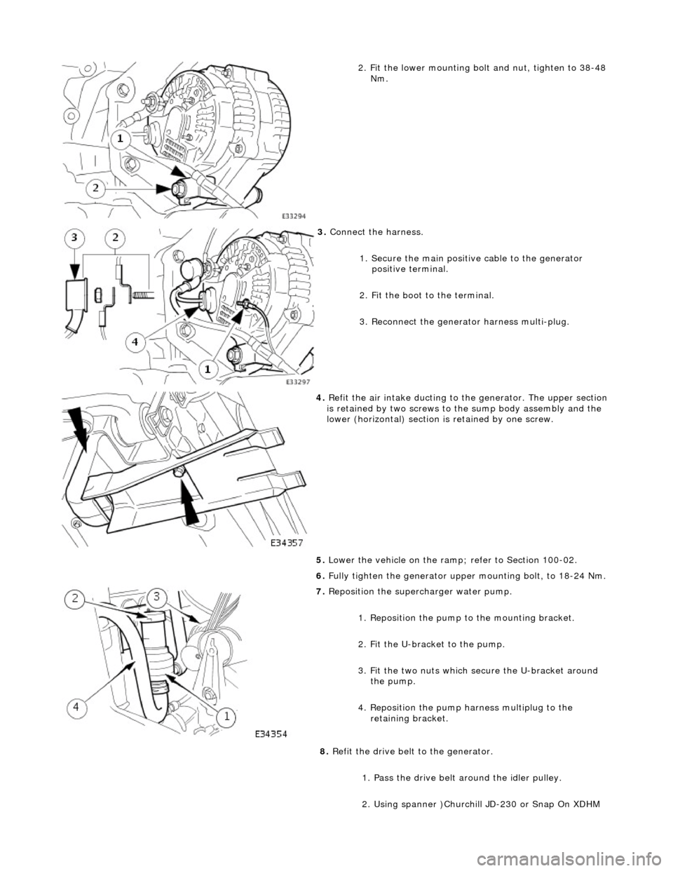
2. Fit the lower mounting bolt and nut, tighten to 38-48
Nm.
3. Connect the harness.
1. Secure the main positive cable to the generator positive terminal.
2. Fit the boot to the terminal.
3. Reconnect the generator harness multi-plug.
4. Refit the air intake ducting to the generator. The upper section
is retained by two screws to the sump body assembly and the
lower (horizontal) section is retained by one screw.
5. Lower the vehicle on the ramp ; refer to Section 100-02.
6. Fully tighten the generator upper mounting bolt, to 18-24 Nm.
7. Reposition the superc harger water pump.
1. Reposition the pump to the mounting bracket.
2. Fit the U-bracket to the pump.
3. Fit the two nuts which secure the U-bracket around the pump.
4. Reposition the pump harness multiplug to the retaining bracket.
8. Refit the drive belt to the generator.
1. Pass the drive belt around the idler pulley.
2. Using spanner )Churchill JD-230 or Snap On XDHM
Page 2383 of 2490
Paint
The inhalation of sprays, fumes, or dust during paint application or sanding processes should always be avoided. Ensure
that there is efficient ventilation / extrac tion at all times. Paint spraying should be confined as far as possible to spray
booths. Personnel with a history of asth ma should not be employed in any process involving the use of isocyanates.
Operators working in a spray booth where isocyanate material is present must use air-fed breathing equipment with air
supplied to the visor at the re commended pressure and filtered to remove oil, water, and fumes. Operators involved in
handling mixing or spraying should wear protective clothing including gloves and goggles, to avoid skin and eye contact.
Particle masks or canister type respir atosr should be worn when sanding.
Applied Heat
When welding, flame cutting, brazing etc, the operator shou ld use as appropriate, goggles, mask / fume extractor and
flameproof protective clothing. It is especially important when working with polyurethane compounds to use air-fed
breathing equipment. Appropriat e fire fighting equipment and personnel trai ned in its use must always be available.
Metal Repair
Appropriate eye and hand protection should be worn when sanding, drilling, cutting, chiselling, flatting or welding. Face
masks or air-fed visors should also be wo rn when sanding or flatting either body solder or fillers. On completion of a
soldering operation, swarf must be re moved from the work area and the operat or must wash his hands thoroughly.
GENERAL REPAIR NOTES
The following advice should be noted before any repair work is carried out.
Disconnect the vehicle battery gr ound lead (disconnect the alternator where electric welding is used) and take note of the
reconnection procedures as detailed in 86.15.15.
Where structural parts are straightened or renewed, a body alignment / straightening jig must be used. The application of
heat, especially excessive heat, reduces the strength of steels, where appropriate therefore, structural sections should be
straightened by cold processes.
Repairs may only be carried out successful ly, and any warranties protected, if genuine Jaguar replacement parts and Jaguar
approved materials are used.
The correct tools, procedures and facilities must always be us ed. The quality of the work must not be compromised by using
inappropriate methods or equipment.
All trim and electrical components in the locality of the repair must be removed or disconnected prior to panel removal /
replacement; this is especially important where hollow sectio ns may contain harnesses, tubes or foam, see section A4.3.5.
WARNING: DO NOT WORK IN THE VICINITY OF A LIVE AIR BAG, REMOVE IT COMPLETELY. READ WORKING
PRACTICES AIR BAG, SECTION 20. ANY SEAT BELT WHICH HAS BEEN WORN IN AN ACCIDENT MUST BE RENEWED.
CAUTION: Electric arc welding should not be used on Jaguar vehicles. The high voltages produced by this process will
cause irreparable damage to the electric al control and microprocessor systems.
The following welding and gas processes are the only ones recommended by Jaguar Cars Ltd.
Welding and Gas Processes
Resistance spot welding, MIG welding and all gas processes may only be carried out on bare, unpainted or unplated metal.
The flanges of panels to be welded toge ther, must be clean, corrosion free and tr eated as appropriate, with either weld-
through primer or inter-weld sealer. Only materials and processes specified in the 'Body Sealing and Preservation Manual'
should be used in the relevant application areas detailed in this section. Refer to 'Zinc Coated Panels' Section