JAGUAR X308 1998 2.G Workshop Manual
X308 1998 2.G
JAGUAR
JAGUAR
https://www.carmanualsonline.info/img/21/7640/w960_7640-0.png
JAGUAR X308 1998 2.G Workshop Manual
Page 717 of 2490
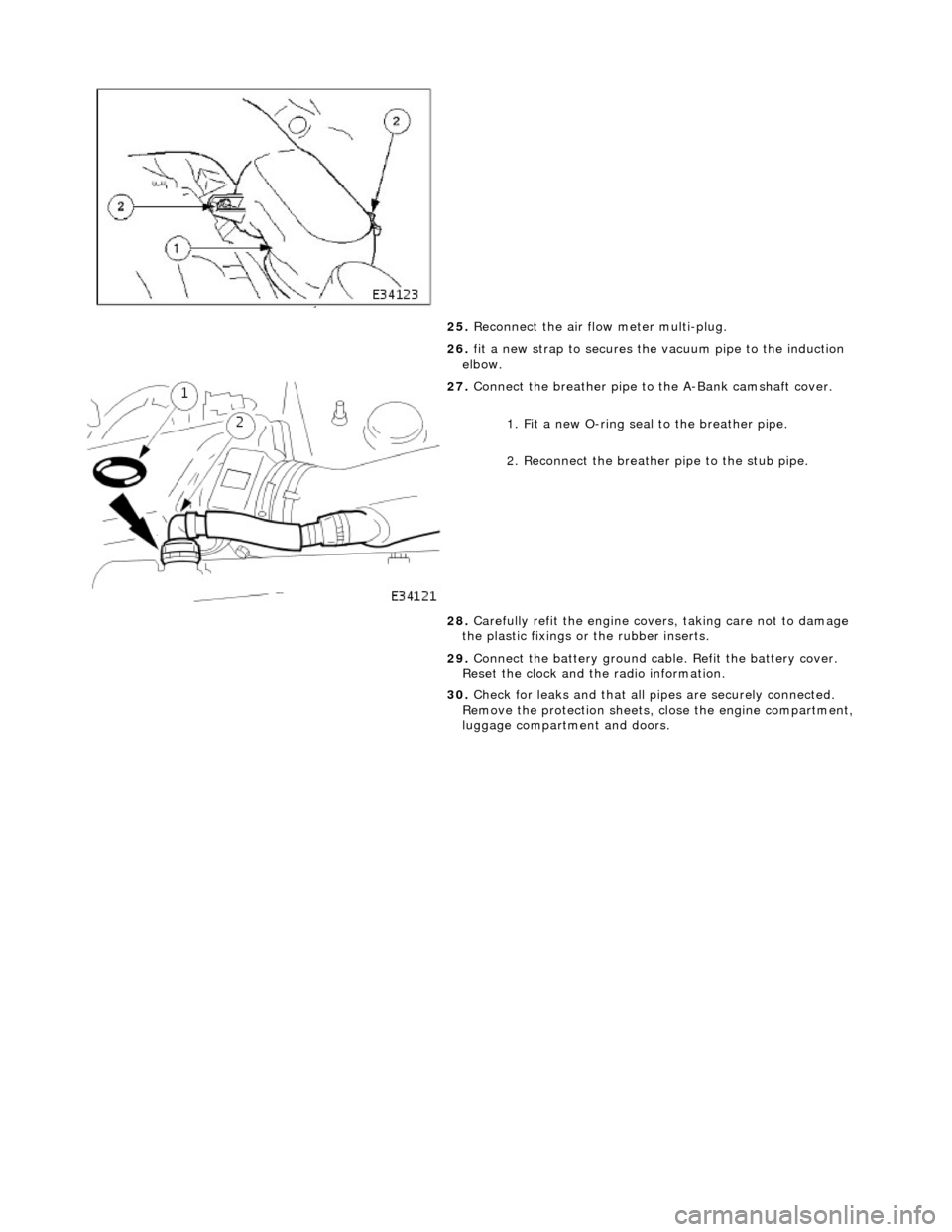
25. Reconnect the air flow meter multi-plug.
26. fit a new strap to secures the vacuum pipe to the induction
elbow.
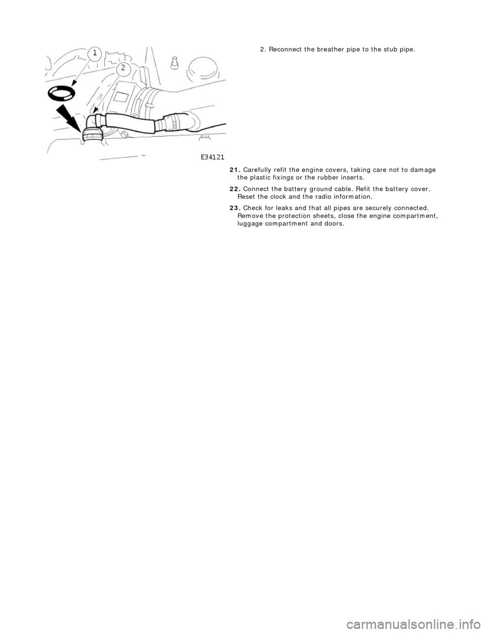
27. Connect the breather pipe to the A-Bank camshaft cover.
1. Fit a new O-ring seal to the breather pipe.
2. Reconnect the breather pipe to the stub pipe.
28. Carefully refit the engine covers, taking care not to damage
the plastic fixings or the rubber inserts.
29. Connect the battery ground cabl e. Refit the battery cover.
Reset the clock and the radio information.
30. Check for leaks and that all pi pes are securely connected.
Remove the protection sheets, close the engine compartment,
luggage compartment and doors.
Page 728 of 2490
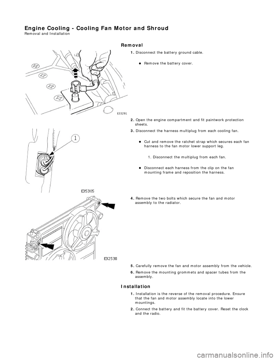
2. Reconnect the breather pipe to the stub pipe.
21. Carefully refit the engine covers, taking care not to damage
the plastic fixings or the rubber inserts.
22. Connect the battery ground cabl e. Refit the battery cover.
Reset the clock and the radio information.
23. Check for leaks and that all pi pes are securely connected.
Remove the protection sheets, close the engine compartment,
luggage compartment and doors.
Page 969 of 2490
Engine Cooling - Cooling Fan Motor and Shroud
Re
moval and Installation
Remov
al
Installation
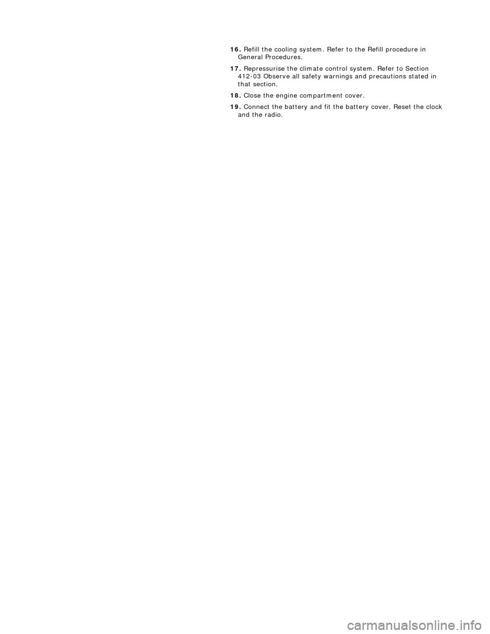
1.
Di
sconnect the batt
ery ground cable.
R
emove the battery cover.
2. Open the engine compartment and fit paintwork protection
sheets.
3. Disc
onnect the harness multip
lug from each cooling fan.
Cut an
d remove the ratchet st
rap which secures each fan
harness to the fan moto r lower support leg.
1. Disconnect the mult iplug from each fan.
Di
sconnect each harness
from the clip on the fan
mounting frame and repo sition the harness.
4. R
emove the two bolts which
secure the fan and motor
assembly to the radiator.
5. Carefully remove the fan and mo tor assembly from the vehicle.
6. Re
move the mounting grommets
and spacer tubes from the
assembly.
1. Installation is the reverse of the remova l procedure. Ensure
that the fan and motor assembly locate into the lower
mountings.
2. Connect the battery and fit the battery cover. Reset the clock
and the radio.
Page 979 of 2490
16
.
Refill the cooling system. Refer to the Refill procedure in
General Procedures.
17. Repressurise the climate cont rol system. Refer to Section
412-03 Observe all safety warnin gs and precautions stated in
that section.
18. Close the engine compartment cover.
19. Connect the battery and fit the battery cover. Reset the clock
and the radio.
Page 986 of 2490
16
. Re
fill the cooling system. Refer to the Refill procedure in
General Procedures.
17. Repressurise the climate cont rol system. Refer to Section
412-03 Observe all safety warnin gs and precautions stated in
that section.
18. Close the engine compartment cover.
19. Connect the battery and fit the battery cover. Reset the clock
and the radio.
Page 1341 of 2490
3. NOTE: Ensure extreme clea nliness and never reuse
transmission fluid.
Using a new gasket, install the fl uid pan and tighten the fixings
to the specified torque figure.
4. Connect the battery and fit the battery cover..
Reset the radio and the clock.
5. Refer to (44.24.02) for fluid fill procedure.
Page 1351 of 2490
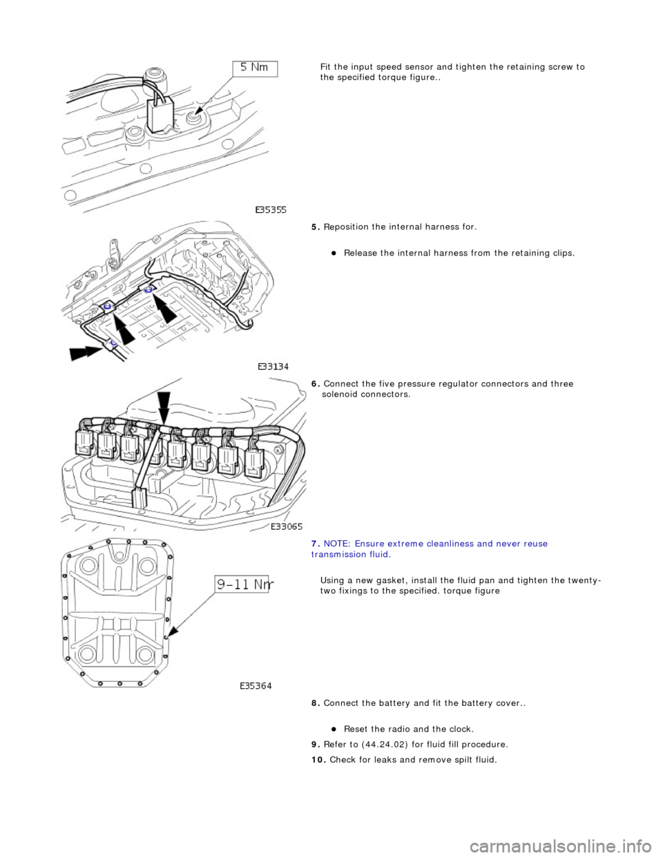
Fit the inpu
t speed sensor and
tighten the retaining screw to
the specified to rque figure..
5. Re
position the inte
rnal harness for.
R
elease the internal harness
from the retaining clips.
6. Connect
the five pressure re
gulator connectors and three
solenoid connectors.
7. N
OTE: Ensure extreme clea
nliness and never reuse
transmission fluid.
Using a new gasket, install the fl uid pan and tighten the twenty-
two fixings to the specified. torque figure
8. Connect the battery and fit the battery cover..
Reset th
e radio and the clock.
9. Refer to (44.24.02) for fluid fill procedure.
10. Check for leaks and remove spilt fluid.
Page 1353 of 2490
Installation
1.
NOTE: M6 fixing.
Connect the multiplug, install the output speed sensor and
securing bracket. Tighten the screw to the specified torque
figure.
2. NOTE: Ensure extreme clea nliness and never reuse
transmission fluid.
Using a new gasket, install the fl uid pan and tighten the twenty-
two fixings to the specified. torque figure.
3. Connect the battery and fit the battery cover..
Reset the radio and the clock.
4. Refer to (44.24.02) for fluid fill procedure.
Page 1356 of 2490
3. NOTE: Ensure extreme clea nliness and never reuse
transmission fluid.
Using a new gasket, install the fl uid pan and tighten the twenty-
two fixings to the specified torque figure.
4. Connect the battery and fit the battery cover..
Reset the radio and the clock.
5. Refer to (44.24.02) for fluid fill procedure.
Page 1358 of 2490
Installation
1.
NOTE: A replacement TCM may only be obtained from an
authorized Jaguar dealer and MU ST be ordered against the VIN.
Fitting a new TCM is the revers e of the removal procedure.
At this point ensure that the ECM is correctly located and
pushed fully rearward against the housing.
2. Connect the battery and fit the battery cover..
Reset the radio and the clock.
