vvt JAGUAR X308 1998 2.G Owner's Manual
[x] Cancel search | Manufacturer: JAGUAR, Model Year: 1998, Model line: X308, Model: JAGUAR X308 1998 2.GPages: 2490, PDF Size: 69.81 MB
Page 573 of 2490

9. F
it the chain tensioning tool 303 - 532 to the exhaust camshaft
sprocket, A-Bank.
Re
position the sprocket (and
the VVT unit) for the most
advantageous position for use of the tool.
R
emove the tool.
10
.
Refit the primary timing chain, A-Bank.
1. Fit the primary chain over the crankshaft sprocket and the VVT unit sprocket. There must be no slack on
the drive side of the primary chain and the VVT unit
must not be rotate d on the camshaft.
11
.
Fit the primary chain tensioner blade.
1. Position the tensioner blade to the cylinder block.
2. Fit the retaining / pivot bolt and tighten it to 12 - 16 Nm.
12. Refit the primary chain tens ioner assembly. Refer to
Operation 12.65.54 in this Section.
U
se a wedge 303 - 533 (or two if required) between the
primary chain tensioner and te nsioner blade, to take up
the slack in the chain.
Page 574 of 2490

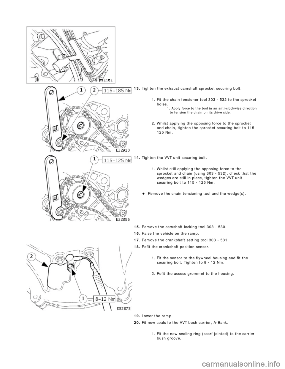
13. Tigh
ten the exhaust camshaft
sprocket securing bolt.
1. Fit the chain tensioner tool 303 - 532 to the sprocket holes.
1. Apply force to the to
ol in
an anti-clockwise direction
to tension the chain on its drive side.
2 .
Whilst applying the opposing force to the sprocket
and chain, tighten the sprock et securing bolt to 115 -
125 Nm.
14 . Tigh
ten the VVT unit securing bolt.
1. Whilst still applying the opposing force to the
sprocket and chain (using 303 - 532), check that the
wedges are still in place, tighten the VVT unit
securing bolt to 115 - 125 Nm.
R e
move the chain tensioning
tool and the wedge(s).
15. Remove the camshaft locking tool 303 - 530.
16. Raise the vehicle on the ramp.
17. Remove the crankshaft setting tool 303 - 531.
18 . R
efit the crankshaft position sensor.
1. Fit the sensor to the fl ywheel housing and fit the
securing bolt. Tighten to 8 - 12 Nm.
2. Refit the access grommet to the housing.
19. Lower the ramp.
20. Fit new seals to the VVT bush carrier, A-Bank.
1. Fit the new sealing ring ( scarf jointed) to the carrier
bush groove.
Page 575 of 2490

2
. Fit a new O-ring to the carrier oil-way.
21
.
NOTE: Lubricate the seal (s carf jointed) and the bush.
Fit the VVT bush carrier to the cylinder block.
1. Fit the bush carrier assembly.
1. C
heck that the seals are in place and that the ring
dowels are engaged squa rely. Fully locate the
assembly as much as possible by hand pressure.
2
. Fit the three securing bolts. Tighten to 19 - 23 Nm.
22
.
Fit new seals to the VVT bush carrier, B-Bank.
1. Fit the new sealing ring (scarf jointed) to the carrier bush groove.
2. Fit a new O-ring to the carrier oil-way.
23
.
NOTE: Lubricate the seal (s carf jointed) and the bush.
Fit the VVT bush carrier to the cylinder block. 1. Fit the bush carrier assembly.
1. C
heck that the seals are in place and that the ring
dowels are engaged squa rely. Fully locate the
assembly as much as possible by hand pressure.
2
. Fit the two securing bolts and one nut. Tighten to 19
- 23 Nm.
24. Refit the Timing Cover. Refer to Operation 12.65.01 in this
Section.
25. Move the engine compartment cover from the service position
and connect the gas struts.
26. Remove the paint protection sheets and close the cover.
27. Connect the battery and fit the battery cover.
Re
fer to the Battery Reconnection Procedure 86.15.15.
Page 586 of 2490

Engine - Crankshaft Outer
Sprocket
In-v
ehic
le Repair
Remov
a
l
S
p
ecial Tool(s)
Camshaft setting
3
03-
530
T
i
ming chain tensioning
303-532
Wedges, primary ch ain
303-533
Cranksha
ft setting
303-531
1. Open the engine compartment and fit paintwork protection
sheets.
2. Set the engine compartment cover to the service access
position.
3. Disc
onnect the batt
ery ground cable.
Re
move the battery cover.
4. Remove the Timing Co ver. Refer to Operation 12.65.01 in this
Section.
5. Remove the VVT bush carrier.
1. Remove the three bolts which secure the carrier to the cylinder block.
Page 588 of 2490

1.
Fit the crankshaft setting peg 303 - 531.
Position the crankshaft so
that the setting
peg engages
fully into the timing slot.
2. Fit and tighten the bolt to secure the setting peg.
12. Remove the damper securing bolt from the crankshaft.
13. Lower the vehicle on the ramp.
14. F
it the camshaft locking tool 303 - 530 to the A-Bank
camshafts, aligning the shafts slightly as necessary.
15. L
oosen the bolt which secures
the sprocket to the camshaft.
16. Loosen
the bolt which secure
s VVT unit to the camshaft.
17. Remove the primary ch ain tensioner bolts.
Page 589 of 2490

I
nstallation
18
.
Remove the tensioner assembly.
1. Remove the tensioner.
2. Remove the tensioner back-plate.
19
.
Remove the chain tensioner blade.
1. Remove the pivot bolt which secures the tensioner blade.
2. Remove the tensioner blade.
20. Remove the chain from the VVT unit and from the crankshaft
sprocket.
21
.
If necessary, remove the sp rocket from the crankshaft.
No
te the orientation of the
sprocket relative to the
sprocket for the B-Bank drive (half a tooth out of line) and
remove the sprocket.
22. Clean and inspect all relevant components.
1. If removed previously, fit the sprocket to the crankshaft.
Page 590 of 2490

The
teeth of the A-Bank and the B-Bank sprockets on the
crankshaft must be out of phas e with each other. If they
are in-phase after fitting, remo ve the sprocket, turn it on
its vertical axis and refit it.
2. Fi
t the chain tensioning tool 303 - 532 to the exhaust camshaft
sprocket.
Re po
sition the sprocket (and
the VVT unit) for the most
advantageous position for use of the tool.
R e
move the tool.
3. Re
fit the primary timing chain.
1. Fit the primary chain to position over the crankshaft sprocket and the VVT unit sprocket. There must be no
slack on the drive side of the primary chain and the
VVT unit must not be rotated on the camshaft.
4. Fit the primary chain tensioner
blade.
1. Position the tensioner blade to the cylinder block.
2. Fit the retaining / pivot bolt and tighten it to 12-16 Nm.
5. Refit the primary chain tensione r assembly. Refer to Operation
12.65.54 in this Section.
U s
e a wedge 303 - 533 (or two if required) between the
primary chain tensioner and te nsioner blade, to take up
the slack in the chain.
Page 591 of 2490

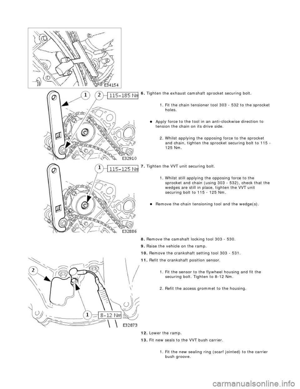
6. Tigh
ten the exhaust camshaft
sprocket securing bolt.
1. Fit the chain tensioner tool 303 - 532 to the sprocket holes.
Appl
y force to the tool in an
anti-clockwise direction to
tension the chain on its drive side.
2. Whilst applying the opposing force to the sprocket and chain, tighten the sprock et securing bolt to 115 -
125 Nm.
7. Tigh
ten the VVT unit securing bolt.
1. Whilst still applying the opposing force to the
sprocket and chain (using 303 - 532), check that the
wedges are still in place, tighten the VVT unit
securing bolt to 115 - 125 Nm.
R
emove the chain tensioning
tool and the wedge(s).
8. Remove the camshaft locking tool 303 - 530.
9. Raise the vehicle on the ramp.
10. Remove the crankshaft setting tool 303 - 531.
11
.
Refit the crankshaft position sensor.
1. Fit the sensor to the fl ywheel housing and fit the
securing bolt. Tighten to 8-12 Nm.
2. Refit the access grommet to the housing.
12. Lower the ramp.
13. Fit new seals to the VVT bush carrier.
1. Fit the new sealing ring (scarf jointed) to the carrier bush groove.
Page 592 of 2490

2.
Fit a new O-ring to the carrier oil-way.
14. F
it the VVT bush carrier to the cylinder block.
Lubric
ate the seal (scarf
jointed) and the bush.
1. Fit the bush carrier assembly.
Check that th e seals are in pl ace an
d that the ring dowels
are engaged squarely. Fully locate the assembly as much
as possible by hand pressure.
2. Fit the three securing bolts. Tighten to 19-23 Nm.
15. Refit the Timing Cover. Refer to Operation 12.65.01 in this
Section.
16. Move the engine compartment cover from the service position
and connect the gas struts.
17. Remove the paint protection sheets and close the cover.
18. Connect the battery and fit the battery cover.
Refe
r to the Battery Reconnection Procedure in Section
414-01.
Page 612 of 2490

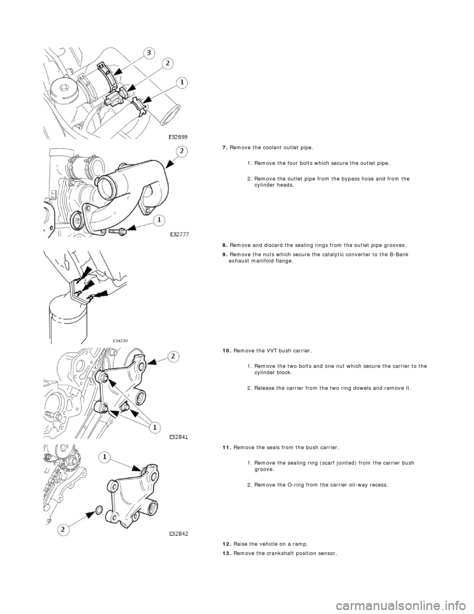
7.
Remove the coolant outlet pipe.
1. Remove the four bolts which secure the outlet pipe.
2. Remove the outlet pipe from the bypass hose and from the cylinder heads.
8. Remove and discard the sealing ring s from the outlet pipe grooves.
9.
Remove the nuts which secure the catalytic converter to the B-Bank
exhaust manifold flange.
10 . Re
move the VVT bush carrier.
1. Remove the two bolts and one nut which secure the carrier to the cylinder block.
2. Release the carrier from the two ring dowels and remove it.
11. R
emove the seals from the bush carrier.
1. Remove the sealing ring (scarf jointed) from the carrier bush groove.
2. Remove the O-ring from the carrier oil-way recess.
12. Raise the vehicle on a ramp.
13. Remove the crankshaft position sensor.