wheel size JAGUAR X308 1998 2.G Workshop Manual
[x] Cancel search | Manufacturer: JAGUAR, Model Year: 1998, Model line: X308, Model: JAGUAR X308 1998 2.GPages: 2490, PDF Size: 69.81 MB
Page 39 of 2490
Before inspecting a component for wear or per
forming a dimensional check,
ensure that it is absolutely clean; a slight smear
of grease can conceal an incipient failure. When a component is to be checked dimensionally against figures quoted for it,
use the correct equipment (surface plates, micrometers, dial gauges etc.) in serviceable condition. The use of makeshift
equipment can be dangerous. Reject a component if its dimensio ns are outside the limits quoted, or if damage is apparent.
A part may be refitted if its critical di mension is exactly to the limit size and it is otherwise satisfactory. Use Plastigauge 12
Type PG-1 for checking bearing surface clearance, e.g. big end bearing shell to crank jour nal. Instructions for the use of
Plastigauge and a scale giving bearing clearances in steps of 0.0025 mm (0.0001 in) are supplied with the package.
Safety
Precautions
• WAR
NINGS:
WORKING ON THE FUEL SYSTEM RESULTS IN FUEL AND FUEL VAPOUR BEING PRESENT IN THE ATMOSPHERE. FUEL
VAPOUR IS EXTREMELY FLAMMABLE, HENCE GREAT CARE MUST BE TAKEN WHILST WORKING ON THE FUEL SYSTEM.
ADHERE STRICTLY TO THE FOLLOWING PRECAUTIONS:
DO
NOT SMOKE IN THE WORK AREA.
DISP
LAY 'NO SMOKING' SIGNS AROUND THE AREA.
DISCONNECT TH
E BATTERY BEFORE WORKING ON THE FUEL SYSTEM.
DO NOT CONNEC
T/DISCONNECT ELECTRICAL CIRCUITS
, USE ELECTRICAL EQUIPMENT OR OTHER TOOLS OR
ENGAGE IN WORKING PRACTICES WHICH IN ANY WAY MAY RESULT IN THE PRODUCTION OF SPARKS.
ENS
URE THAT A CO2 FIRE EXTINGUISHER IS CLOSE AT HAND.
ENS
URE THAT DRY SAND IS AVAILABLE TO SOAK UP ANY FUEL SPILLAGE.
EMP
TY FUEL USING SUITABLE FIRE PROOF EQUIPMENT IN
TO AN AUTHORIZED EXPLOSION PROOF CONTAINER.
DO NOT EMP
TY FUEL WHILE WORKING IN A WORKSHOP OR A PIT.
ENS
URE THAT WORKING AREA IS WELL VENTILATED.
ENS
URE THAT ANY WORK ON THE FUEL SYSTEM IS ON
LY CARRIED OUT BY EXPERIENCED AND WELL QUALIFIED
MAINTENANCE PERSONNEL.
ENS
URE THAT FUME EXTRACTION EQUIPMENT IS USED WHERE APPROPRIATE.
FUME EXTRACTION EQUIPMENT MUST BE IN OPERATION WHEN SOLVENTS ARE USED E.G. TRICHLOROETHANE,
WHITE SPIRIT, SBP3, METHYLENE CHLORIDE, PERCHLORETHY LENE. DO NOT SMOKE IN THE VICINITY OF VOLATILE
DEGREASING AGENTS.
General workshop practices:
Disc
onnect the grounded termin
al of the vehicle battery.
D
o not apply heat in an attempt to free seized nuts or fitt
ings; as well as causing damage to protective coatings,
there is a risk of damage from stray heat to electronic equipment and brake lines.
Keep oils and solven
ts away from naked flames and other sour
ces of ignition.
Adhere str
ictly to handling and safety inst
ructions given on containers and labels.
E
nsure that a suitab
le form of fire extinguisher is conveniently located.
Wh
en using electrical tools and equipment, inspect the power
lead for damage and check that it is properly earthed.
D
o not leave tools, equipment, spilt oil etc. around the work area.
Working beneath a vehicle:
Wh
enever possible, use a ramp or
pit in preference to jacking.
Posit
ion chocks at the wheels as we
ll as applying the parking brake.
N
ever rely on a jack alone to support a
vehicle; use axle stands, or blocks care fully placed at the jacking points, to
provide a rigid location.
Ch
eck that any lifting equipment used has adeq
uate capacity and is fully serviceable.
Working on air conditioning systems:
D
o not disconnect any pipes of the refrigeration system
unless you are trained and instructed to do so; a refrigerant
is used which can cause blindness if allowed to come into contact with the eyes.
Health Protection
P
rolonged and repeated contact with mineral oil will result in the removal of natural oils from the skin, leading to dryness,
In
spection
Page 259 of 2490
W
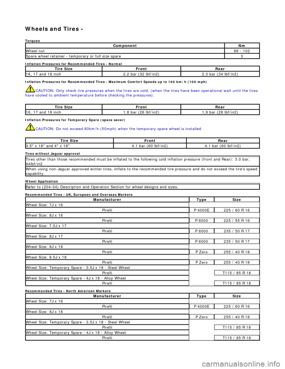
heels and Tires -
Torq
ues
Inflation Pressures for Recommended Tires - Normal
Inflation Pressures for Recommended Tires - Maxi mum Comfort Speeds up to 160 km/h (100 mph)
CAUTI
ON: Only check tire pressures when
the tires are cold, (when the tires have been operational wait until the tires
have cooled to ambient temperature before checking the pressures).
Inf
lation Pressures for Temporary Spare (space saver)
CAU
TION: Do not exceed 80km/h (50mph) when the temporary spare
wheel is installed.
Tires
without Jaguar approval
Wheel Application
Recommended Tires - UK, European and Overseas Markets
Recommended Tires - North American Markets
Com
ponent
Nm
Wh
eel nut
8
8 - 102
Spare wheel r
etainer - temporary or full size spare
3
Ti
re Size
Fr
ont
Rear
1
6, 17 and 18 inch
2.
2 bar (32 lbf/in2)
2.
3 bar (34 lbf/in2)
Ti
re Size
Fr
ont
Rear
1
6, 17 and 18 inch
1.
8 bar (26 lbf/in2)
1.
9 bar (28 lbf/in2)
Ti
re Size
Fr
ont
Rear
3.
5" x 18" and 4" x 18"
4.
1 bar (60 lbf/in2)
4.
1 bar (60 lbf/in2)
Ti
res other than those recommended must be inflated to the following cold
inflation pressure (front and Rear): 3.0 bar,
44lbf/in2
Wh
en using non-Jaguar approved winter ti
res, inflate to the recommended tire pressure and do not exceed the tire's speed
capability.
R
efer to (204-04) Description and Operation Section for wheel designs and sizes.
Manufact
urer
Ty
pe
Si
ze
W
heel Size: 7J x 16
Pire
lli
P 40
00E
2
25 / 60 R 16
W
heel Size: 8J x 16
Pire
lli
P 60
00
2
25 / 55 R 16
Wh
eel Size: 7.5J x 17
Pire
lli
P 60
00
2
35 / 50 R 17
W
heel Size: 8J x 17
Pire
lli
P 60
00
2
35 / 50 R 17
W
heel Size: 8J x 18
Pire
lli
P Ze
ro
2
55 / 40 R 18
Wh
eel Size: 8.5J x 18
Pire
lli
P Ze
ro
2
55 / 40 R 18
Wh
eel Size: Temporary Spare - 3.5J x 18 - Steel Wheel
Pire
lli
T1
15 / 85 R 18
W
heel Size: Temporary Spare - 4J x 18 - Alloy Wheel
Pire
lli
T1
15 / 85 R 18
Manufact
urer
Ty
pe
Si
ze
W
heel Size: 7J x 16
Pire
lli
P 40
00E
2
25 / 60 R 16
W
heel Size: 8J x 18
Pire
lli
P Ze
ro
2
55 / 40 R 18
Wh
eel Size: Temporary Spare - 3.5J x 18 - Steel Wheel
Pire
lli
T1
15 / 85 R 18
W
heel Size: Temporary Spare - 4J x 18 - Alloy Wheel
Pire
lli
T1
15 / 85 R 18
Page 261 of 2490
W
heels and Tires - Wheels and Tires
Description an
d Operation
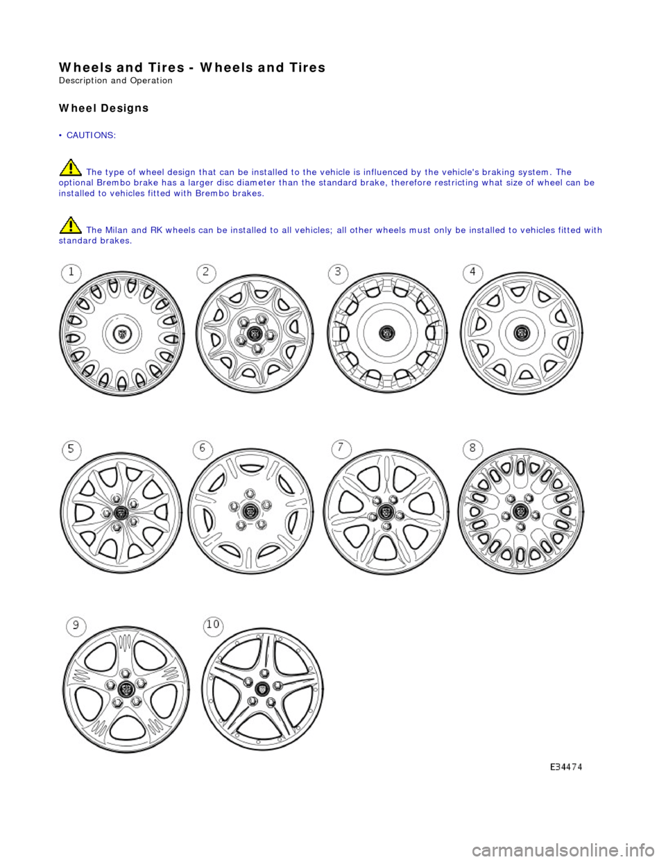
Wheel Desi
gns
• C
AUTIONS:
The type of wheel design that can be installed to the vehicle is influenced by the vehicle's braking system. The
optional Brembo brake has a larger disc diameter than the stan dard brake, therefore restricting what size of wheel can be
installed to vehicles fi tted with Brembo brakes.
The Milan and RK wheels can be installed to all vehicles; all other wheels must only be installed to vehicles fitted with
standard brakes.
Page 263 of 2490
O
ne locking wheel nut is fitted to each road wheel and can on
ly be removed by using the correctly coded socket. For road
wheels with exposed wheel nuts, each locking wheel nut is provided with a cover, which is removed using the cover removal
tool.
Locking wheel nuts have different coded keyway combinations with corresponding coded sockets. The correct socket, and
cover removal tool are supplied with the vehicle toolkit. Sets of sockets are available to Jaguar dealers.
Temporary Spare Wheel
•
NOTE: When using this type of spare wheel note that:
Speed
must not exceed 80 km/h (50 mph).
The normal ro
ad wheel must be reinstalled as soon as possible.
On
ly one temporary wheel may be installed to the vehicle.
Tracti
on control (where fitted
) must be switched OFF.
In certain markets, the spare wheel supplied with the vehicle is of the temporary-use type, it is narrower than the normal
road wheel and takes up less room in the luggage compartment.
Tire
s
The
radial ply tires shown in the 204-04
Specification Section are recommended by Jaguar to meet the high speed
performance of the vehicle. Only tires of identical specification may be fitted as replacements. Unde r no circumstances must
cross-ply tires be fitted.
Tire Inflation Pressures
Al
l recommended tires, including winter tire
s, must be inflated to the pressures shown in the 204-04 Specification Section.
Inflation pressures must only be checked when the tires are cold.
Tire Replac
ement and Wheel-Interchanging
W
hen renewal of tires is necessary, it is
preferable to fit a complete set. If two replacement tires are fitted (to one axle),
they must be of the same manufacturer and type as those on the other axle.
No attempt must be made to interchange wh eels from the front to the rear or vice-versa, as wear produc es a characteristic
pattern on each tire depending upon its po sition on the vehicle. If this position is changed after wear has occurred, the
performance of the tire w ill be adversely affected.
It should be remembered that new tires must be balanced befo re installing to the vehicle.
Win
ter Tires
•
NOTE: Speed must not exceed 210 km/h (131 mph) when winter tires are installed.
Jaguar recommended winter tires as specified in 204-04 Specification Section must only be fitted in complete four-wheel
sets of the same type and size.
Snow Chains and Spike Spider Traction System
Jagu
ar recommended snow chains, must on
ly be installed when using 16 inch wheels with 255/60 R16 winter tires.
• NOTE: When using snow chains or the spike spider traction system, note that:
Snow ch
ains and the spike spider
traction system must only be fitted to the rear wheels.
O
nly Jaguar recommended snow chains and spik
e spider traction system must be used.
The m
aximum permissible speed with winter tires and snow chains or the spike spider traction system fitted is 48
km/h (30 mph).
Tracti
on control (where fitted) must be
switched OFF when using snow chains or the spike spider traction system.
Page 264 of 2490
Snow chain
s and the spike spider tr
action system must not be used on roads which are clear of snow.
The Jaguar recommended spike spider tracti on system can be used on all wheel and tire sizes, except the temporary spare
wheel.
Asym metric
Tires
Some
tir
es recommended by Jaguar are as
ymmetric. Inner and outer markers embossed on the tire walls must be observed
to ensure the correct installati on of the tire to the wheel.
Tread We
ar Indicator
• NO
TE: Tire condition must comply with prevailing local legislation.
Tread wear indicators are molded into the bottom of the tr ead grooves across the width of the tire. The tire must be
renewed when tread wear indicators become visible at the surface of the tread.
Page 265 of 2490
W
heels and Tires - Wheels and Tires
D
iagnosis and Testing
General Not
es
1.
1. Factory in
stalled tires and wheels are designed to provide optimum ride and ha
ndling characteristics when inflated
to the recommended inflation pressures, with vehicle loads not exceeding the full-rated load capacity.
2. 2. Correct tire pressures and driv ing technique have an important influence on tire life. Heavy cornering, excessively
rapid acceleration and unnecessary sharp braking increase tire wear.
3. 3. Replacement tires should follow the recommended:
Size
.
Speed
rating.
Load range. Radial c
onstruction type.
4. 4. The use of any other size or type of wheel / tire may seriously affect:
Safety. Ri
de.
Handlin
g.
Speed
ometer / odometer calibration.
Vehi
cle ground clearance.
Ti
re clearance between
body and chassis.
Wh
eel bearing life.
Brake cooli
ng.
5. 5. Wheels must be renewed when:
Impact damaged. Heavil
y corroded.
Porous W
heel stud holes or se
ats become damaged.
They h
ave excessive radial or lateral runout.
Safety Notes
• WAR
NINGS:
DO NOT MIX DIFFERENT TYPES OF TIRES ON THE SAM E VEHICLE, HANDLING MAY BE SERIOUSLY AFFECTED
RESULTING IN LOSS OF CONTROL.
DO NOT MIX DIFFERENT TYPES OF TIRES ON THE SAM E VEHICLE, HANDLING MAY BE SERIOUSLY AFFECTED
RESULTING IN LOSS OF CONTROL.
A TIRE AND WHEEL MUST ALWAYS BE CORRECTLY MATCHED. WIDER OR NARROWER TIRES THAN RECOMMENDED
COULD CAUSE DANGER THROUGH SUDDEN DEFLATION.
WHEN USING THE TEMPORARY SPARE WHEEL, SPEED MUST NOT EXCEED 80 KM/H (50 MPH). DRIVE WITH CAUTION
AND REPLACE WITH THE SPECIFIED WHEEL / TIRE ASSEMBLY AS SOON AS POSSIBLE.
TRACTION CONTROL (IF AVAILABLE) MUST NOT BE ENGAGED WITH THE TEMPORARY SPARE WHEEL FITTED.
Page 309 of 2490
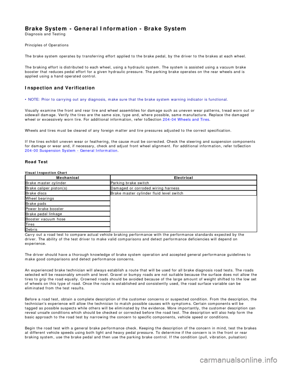
Brake System - General Inform
ation - Brake System
D
iagnosis and Testing
Principles of Operations
The brake system operates by transferring effort applied to th e brake pedal, by the driver to the brakes at each wheel.
The braking effort is distributed to each wheel, using a hydraulic system. The system is assisted using a vacuum brake
booster that reduces pedal effort for a given hydraulic pressure. The parking brake operates on the rear wheels and is
applied using a hand operated control.
I
nspection and Verification
•
NOTE: Prior to carrying out any diagno
sis, make sure that the brake system warning indicator is functional.
Visually examine the front and rear tire and wheel assemblies for damage such as un even wear patterns, tread worn out or
sidewall damage. Verify the tires are th e same size, type and, where possible, same manufacture. Replace the damaged
wheel or excessively worn tire. For a dditional information, refer toSection 204
-0
4 Wheels and Tires
.
W
heels and tires must be cleared of an
y foreign matter and tire pressures ad justed to the correct specification.
If the tires exhibit uneven wear or feathering, the cause must be corrected. Check the steering and suspension components
for damage or wear and, if ne cessary, check and adjust front wheel alignment. For additional information, refer toSection
204
-00 Suspen
sion System
- General Informati
on
.
Road Test
V
isual Inspection Chart
Carr
y out a road test to compare actual vehicle braking performance with the
performance standards expected by the
driver. The ability of the test driver to make valid compar isons and detect performance deficiencies will depend on
experience.
The driver should have a thorough knowledge of brake system operation and accepted general performance guidelines to
make good comparisons and de tect performance concerns.
An experienced brake technician will always establish a route that will be used for all br ake diagnosis road tests. The roads
selected will be reasonably smooth and level. Gravel or bump y roads are not suitable because the surface does not allow the
tires to grip the road equally. Crowned roads should be avoide d because of the large amount of weight shifted to the low set
of wheels on this type of road. Once th e route is established and consistently used, the road surface variable can be
eliminated from the test results.
Before a road test, obtain a complete description of the customer concerns or suspec ted condition. From the description, the
technician's experience will allow the te chnician to match possible causes with symptoms. Certain components will be
tagged as possible suspects while others wi ll be eliminated by the evidence. More importantly, the customer description can
reveal unsafe conditions which should be ch ecked or corrected before the road test. The description will also help form the
basic approach to the road test by narrowing the concern to specific components, vehicle speed or conditions.
Begin the road test with a general brake performance check. Keeping the description of the concern in mind, test the brakes
at different vehicle speeds using both ligh t and heavy pedal pressure. To determine if the concern is in the front or rear
braking system, use the brake pe dal and then use the parking brake control. If the condition (pull, vibration, pulsation)
MechanicalElectrical
Brake m
aster cylinder
Parkin
g brake switch
Brake ca
liper piston(s)
D
amaged or corroded wiring harness
Brake di
scs
B
rake master cylinder fluid level switch
Wh
eel bearin
gs
Brake pads
Power brake booster
Brake ped
al linkage
Boost
er vacuum hose
Tire
s
De
bris
Page 460 of 2490
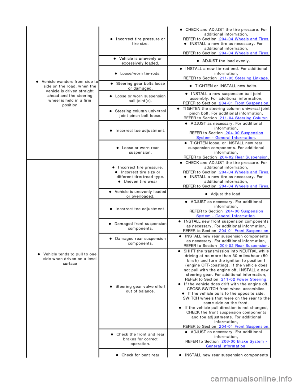
Vehicl
e wanders from side to
side on the road, when the vehicle is driven straight ahead and the steering wheel is held in a firm position
Incorrect ti re
pressure or
tire size.
CHECK and ADJ
UST the tire pressure. For
additional information,
REFER to Section 204
-0 4
Wheels and Tires
. IN
ST
ALL a new tire as necessary. For
additional information,
REFER to Section 204
-0 4
Wheels and Tires
.
Vehi
cl
e is unevenly or
excessively loaded.
A D
JUST the load evenly.
Loose/worn ti
e-
rods.
INST
ALL a ne
w tie-rod
end. For additional
information,
REFER to Section 211
-0 3
Steering Linkage
.
Steeri
ng gear bolts loose
o
r damaged.
TIGHTE
N or INSTALL
new bolts.
Loose or worn suspensi
on
ball jo
int(s).
INST
ALL a ne
w suspension ball joint
assembly. For additional information,
REFER to Section 204
-01 Fron
t Suspension
.
Steeri
ng column uni
versal
joint pinch bolt loose.
TI G
HTEN the steering column universal joint
pinch bolt. For additi onal information,
REFER to Section 211
-0 4
Steering Column
.
Incorre
ct
toe adjustment.
ADJUS
T as necessary. For additional
information,
REFER to Section 204
-00 Sus
pension
Sy
ste
m
- General
Information
.
Loose or worn rear
susp
ension.
TIGHTEN
loose, or IN
STALL new rear
suspension components. For additional information,
REFER to Section 204
-0 2
Rear Suspension
.
Vehicle t
e
nds to pull to one
side when driven on a level surface
Incorrect ti
re pressure.
Incorrect
ti
re size or
different tire/tread type.
Uneven tire wear
CHECK and ADJ
UST the tire pressure. For
additional information,
REFER to Section 204
-0 4
Wheels and Tires
. IN
ST
ALL a new tire as necessary. For
additional information,
REFER to Section 204
-04
Wheels and Tires
.
Vehicl
e is unevenly loaded
or overloaded.
Adjust the load
.
Incorre
ct
toe adjustment.
ADJUS
T as necessary. For additional
information,
REFER to Section 204
-00 Sus
pension
Sy
ste
m
- General
Information
.
Dam
a
ged front suspension
components.
I N
STALL new front suspension components
as necessary. For addi tional information,
REFER to Section 204
-01 Fron
t Suspension
.
Damaged rear
suspen
sion
components.
INST ALL ne
w rear suspension components
as necessary. For addi tional information,
REFER to Section 204
-0 2
Rear Suspension
.
Steeri
ng gear val
ve effort
out of balance.
SHIF T the
transmission into NEUTRAL while
driving at no more than 30 miles/hour (50 km/h) and turn the ignition to position I
(engine OFF-coasting). If the vehicle does
not pull with the engine off, INSTALL a new steering gear. For additional information,
REF E
R to Section 211
-0
2
Power Steering
. If t
he
vehicle does drift with the engine off,
CROSS SWITCH front wheel assemblies.
If the
vehicle pulls to
the opposite side,
SWITCH wheels that were on the rear to the
same side on the front.
If the v
ehicle pull dire
ction is not changed,
CHECK the front susp ension components
and toe adjustments. For additional information,
REFER to Section 204
-01 Fron
t Suspension
.
Chec
k
the front and rear
brakes for correct operation.
ADJUS
T as necessary. For additional
information,
REFER to Section 206
-0 0
Brake System
-
General Informati on.
Check fo
r bent rear
INST
ALL ne
w rear suspension components
Page 461 of 2490
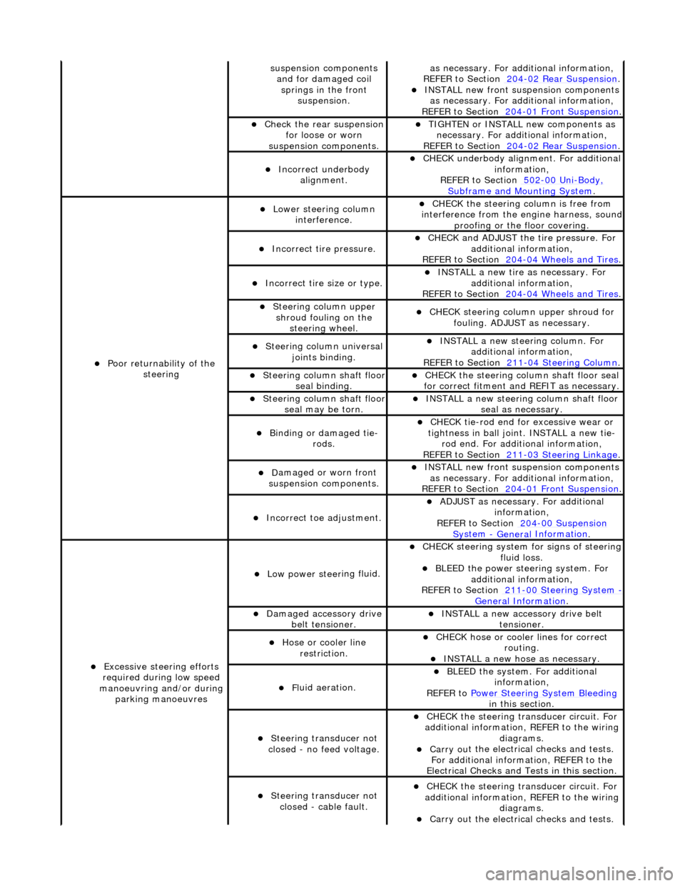
sus
pension components
and for damaged coil springs in the front suspension.
as necessary. For addi tional information,
REF
ER to Section 204
-0
2 Rear Suspension
. I
NSTALL new front suspension components
as necessary. For addi tional information,
REFER to Section 204
-01
Front Suspension
.
Chec
k the rear suspension
for loose or worn
suspension components.
TIGHTE
N or INSTALL new components as
necessary. For additi onal information,
REFER to Section 204
-0
2 Rear Suspension
.
Incorre
ct underbody
alignment.
CHECK
underbody alignment. For additional
information,
REFER to Section 502
-00
Uni
-Body, Subframe and M
ounting System
.
Poor r
eturnability of the
steering
Lower steeri
ng column
interference.
CHECK
the steering co
lumn is free from
interference from the en gine harness, sound
proofing or the floor covering.
Incorrect
tire pressure.
CHECK
and ADJUST the tire pressure. For
additional information,
REFER to Section 204
-0
4 Wheels and Tires
.
Incorrect
tire size or type.
IN
STALL a new tire as necessary. For
additional information,
REFER to Section 204
-0
4 Wheels and Tires
.
Steeri
ng column upper
shroud fouling on the steering wheel.
CHECK
steering column upper shroud for
fouling. ADJUST as necessary.
Steeri
ng column universal
joints binding.
IN
STALL a new steering column. For
additional information,
REFER to Section 211
-0
4 Steering Column
.
Steeri
ng column shaft floor
seal binding.
CHE
CK the steering column shaft floor seal
for correct fitm ent and REFIT as necessary.
Steeri
ng column shaft floor
seal may be torn.
IN
STALL a new steering column shaft floor
seal as necessary.
Bin
ding or damaged tie-
rods.
CHECK
tie-rod end for excessive wear or
tightness in ball joint. INSTALL a new tie- rod end. For additional information,
REFER to Section 211
-0
3 Steering Linkage
.
D
amaged or worn front
suspension components.
I
NSTALL new front suspension components
as necessary. For addi tional information,
REFER to Section 204
-01
Front Suspension
.
Incorre
ct toe adjustment.
AD
JUST as necessary. For additional
information,
REFER to Section 204
-00
Suspension
Sy
stem
- General
Information
.
Excessive steeri
ng efforts
required during low speed
manoeuvring and/or during parking manoeuvres
Low power steer
ing fluid.
CHE
CK steering system
for signs of steering
fluid loss.
BLEE
D the power steering system. For
additional information,
REFER to Section 211
-0
0 Steering System
- General Informati
on
.
Damaged accessory driv
e
belt tensioner.
INST
ALL a new accessory drive belt
tensioner.
Hose or cooler li
ne
restriction.
CHECK
hose or cooler lines for correct
routing.
INST
ALL a new hose as necessary.
Fl
uid aeration.
BLEE
D the system. For additional
information,
REFER to Power Steering System Bleeding
in t
his section.
Steeri
ng transducer not
closed - no feed voltage.
CHECK
the steering transducer circuit. For
additional information, REFER to the wiring diagrams.
Carry ou
t the electrical checks and tests.
For additional information, REFER to the
Electrical Checks and Tests in this section.
Steeri
ng transducer not
closed - cable fault.
CHECK
the steering transducer circuit. For
additional information, REFER to the wiring diagrams.
Carry ou
t the electrical checks and tests.
Page 488 of 2490
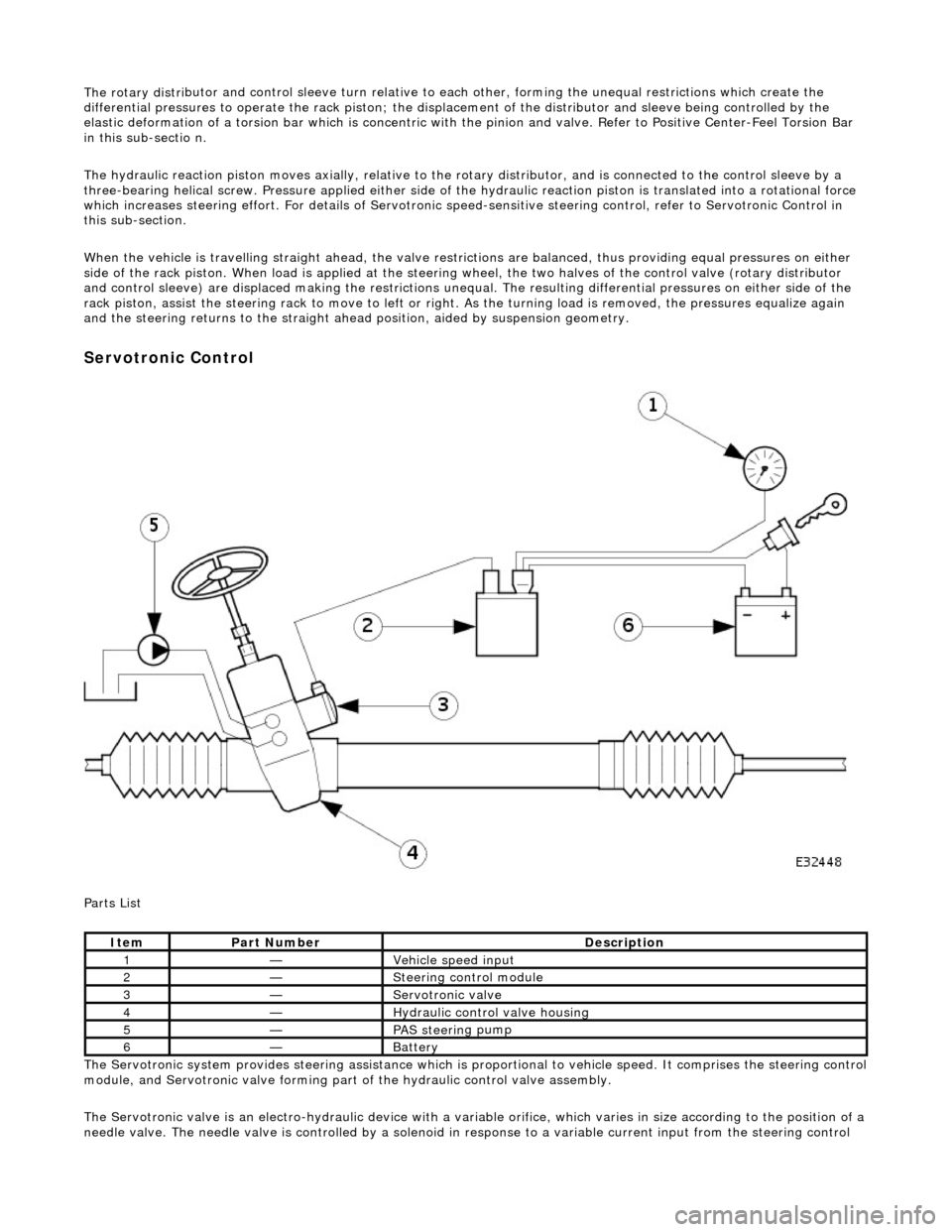
The rotary distri
butor and control sleeve turn relative to ea
ch other, forming the unequal restrictions which create the
differential pressures to operat e the rack piston; the displacement of the di stributor and sleeve being controlled by the
elastic deformation of a torsion bar which is concentric with the pinion and valve. Refer to Positive Center-Feel Torsion Bar
in this sub-sectio n.
The hydraulic reaction piston moves axially, relative to th e rotary distributor, and is connected to the control sleeve by a
three-bearing helical screw. Pressure applied either side of the hydraulic reaction piston is translated into a rotational force
which increases steering effort. For detail s of Servotronic speed-sensitive steering control, refer to Servotronic Control in
this sub-section.
When the vehicle is travelling straight ah ead, the valve restrictions are balanced, thus providing equal pressures on either
side of the rack piston. When load is a pplied at the steering wheel, the two halves of the control valve (rotary distributor
and control sleeve) are displaced making the restrictions unequa l. The resulting differential pressures on either side of the
rack piston, assist the steering rack to mo ve to left or right. As the turning load is removed, the pressures equalize again
and the steering return s to the straight ahead position , aided by suspension geometry.
Serv
otronic Control
P a
rts List
The Servotronic system provides steering assistance which is pr oportional to vehicle speed. It comprises the steering control
module, and Servotronic valve forming part of the hydraulic control valve assembly.
The Servotronic valve is an electro-hydrauli c device with a variable orifice, which varies in size according to the position of a
needle valve. The needle valve is controlled by a solenoid in response to a variable current input from the steering control
Ite
m
Part
Number
Descr
iption
1—Vehi
cl
e speed input
2—Steeri
ng control
module
3—Servotronic valve
4—Hydraulic
control valve housing
5—PAS stee
rin
g pump
6—Batt
ery