sensor JAGUAR X308 1998 2.G Workshop Manual
[x] Cancel search | Manufacturer: JAGUAR, Model Year: 1998, Model line: X308, Model: JAGUAR X308 1998 2.GPages: 2490, PDF Size: 69.81 MB
Page 1391 of 2490
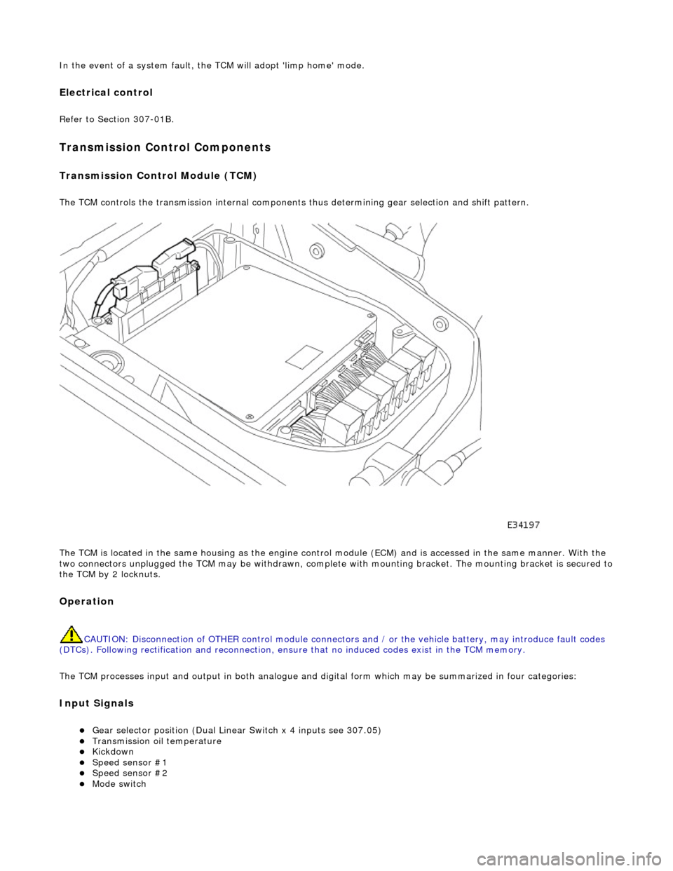
In the event of a system fault, the TCM will adopt 'limp home' mode.
Electrical control
Refer to Section 307-01B.
Transmission Control Components
Transmission Control Module (TCM)
The TCM controls the transmission internal components thus determining gear selection and shift pattern.
The TCM is located in the same housing as the engine control module (ECM) and is accessed in the same manner. With the
two connectors unplugged the TCM may be withdrawn, complete with mounting bracket. The mounting bracket is secured to
the TCM by 2 locknuts.
Operation
CAUTION: Disconnection of OTHER contro l module connectors and / or the vehicle battery, may introduce fault codes
(DTCs). Following rectification and reconnection, ensu re that no induced codes exist in the TCM memory.
The TCM processes input and output in both analogue and di gital form which may be summarized in four categories:
Input Signals
Gear selector position (Dual Linear Switch x 4 inputs see 307.05) Transmission oil temperature Kickdown Speed sensor #1 Speed sensor #2 Mode switch
Page 1395 of 2490
and/or increased performance as appropriate.
Serial Communications Interfaces
Controller Area Network (CAN)
The TCM is an integral part of the CAN system which facilita tes the interchange of real-time data between control modules
and sensors; refer to 303-14 fo r a full description of CAN.
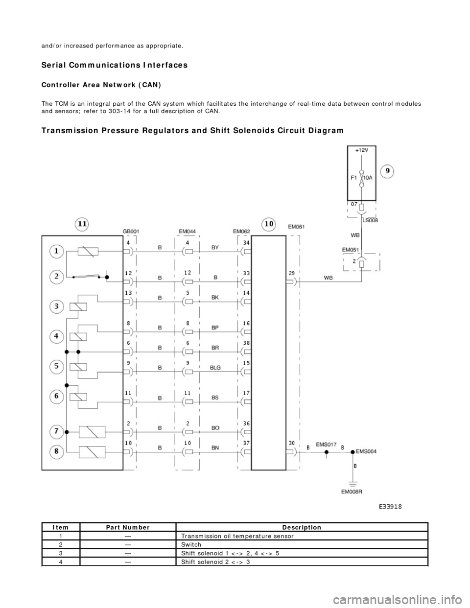
Transmission Pressure Regulators and Shift Solenoids Circuit Diagram
ItemPart NumberDescription
1—Transmission oil temperature sensor
2—Switch
3—Shift solenoid 1 <-> 2, 4 <-> 5
4—Shift solenoid 2 <-> 3
Page 1396 of 2490
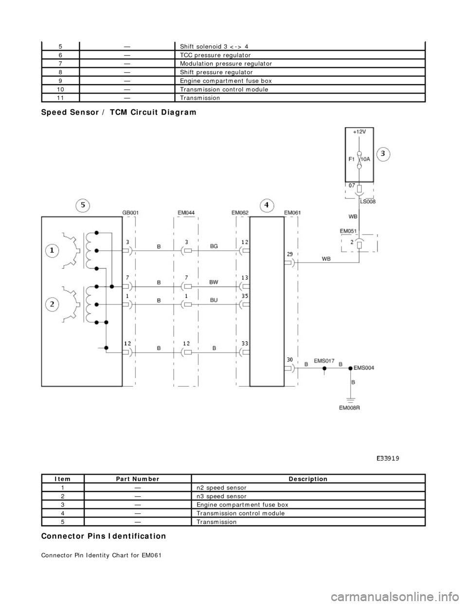
Speed Sensor / TCM Circuit Diagram
Connector Pins Identification
Connector Pin Identity Chart for EM061
5—Shift solenoid 3 <-> 4
6—TCC pressure regulator
7—Modulation pressure regulator
8—Shift pressure regulator
9—Engine compartment fuse box
10—Transmission control module
11—Transmission
ItemPart NumberDescription
1—n2 speed sensor
2—n3 speed sensor
3—Engine compartment fuse box
4—Transmission control module
5—Transmission
Page 1397 of 2490
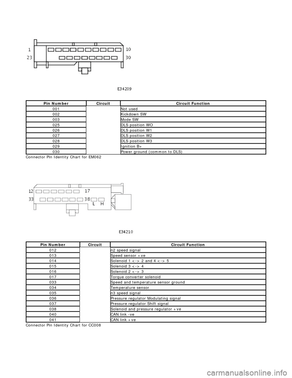
Connector Pin Identity Chart for EM062
Connector Pin Identity Chart for CC008
Pin NumberCircuitCircuit Function
001Not used
002Kickdown SW
003Mode SW
025DLS position WO
026DLS position W1
027DLS position W2
028DLS position W3
029Ignition B+
030Power ground (common to DLS)
Pin NumberCircuitCircuit Function
012n2 speed signal
013Speed sensor +ve
014Solenoid 1 <-> 2 and 4 <-> 5
015Solenoid 3 <-> 4
016Solenoid 2 <-> 3
017Torque converter solenoid
033Speed and temperature sensor ground
034Temperature sensor
035n3 speed signal
036Pressure regulator Modulating signal
037Pressure regulator Shift signal
038Solenoid and pressure regulator +ve
040CAN link -ve
041CAN link +ve
Page 1398 of 2490
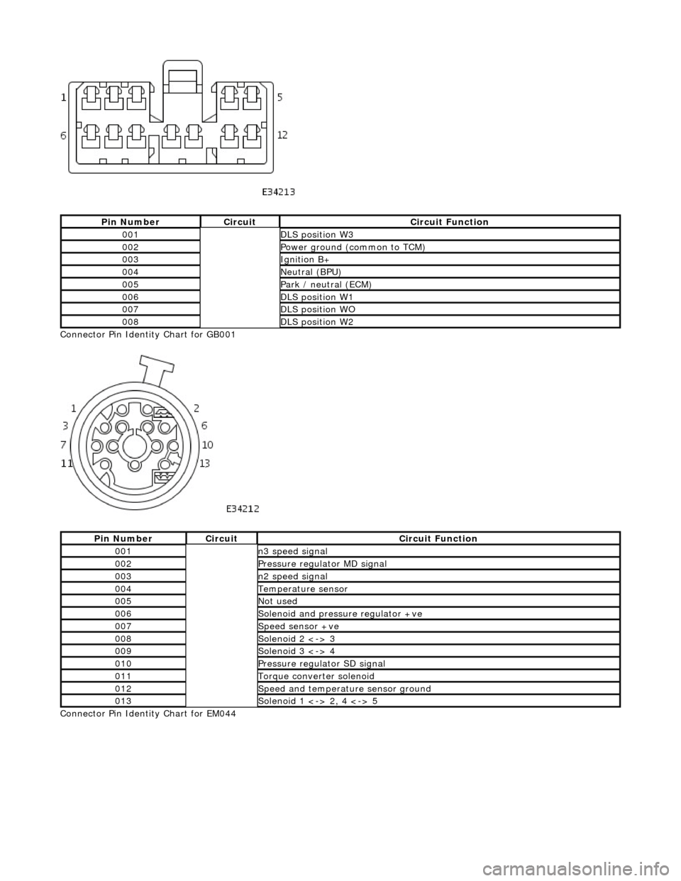
Connector Pin Identity Chart for GB001
Connector Pin Identity Chart for EM044
Pin NumberCircuitCircuit Function
001DLS position W3
002Power ground (common to TCM)
003Ignition B+
004Neutral (BPU)
005Park / neutral (ECM)
006DLS position W1
007DLS position WO
008DLS position W2
Pin NumberCircuitCircuit Function
001n3 speed signal
002Pressure regulator MD signal
003n2 speed signal
004Temperature sensor
005Not used
006Solenoid and pressure regulator +ve
007Speed sensor +ve
008Solenoid 2 <-> 3
009Solenoid 3 <-> 4
010Pressure regulator SD signal
011Torque converter solenoid
012Speed and temperature sensor ground
013Solenoid 1 <-> 2, 4 <-> 5
Page 1399 of 2490

Pin NumberCircuitCircuit Function
001n3 speed signal
002Pressure regulator MD signal
003n2 speed signal
004Temperature sensor
005Solenoid 1 <-> 2, 4 <-> 5
006Solenoid and pressure regulator +ve
007Speed sensor +ve
008Solenoid 2 <-> 3
009Solenoid 3 <-> 4
010Pressure regulator SD signal
011Torque converter solenoid
012Speed and temperature sensor ground
Page 1400 of 2490
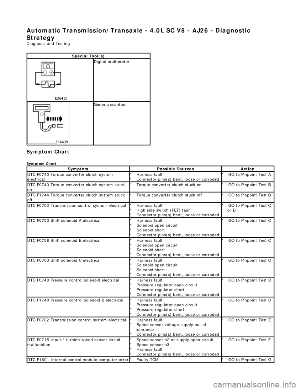
Automatic Transmission/Transaxle - 4.0L SC V8 - AJ26 - Diagnostic
Strategy
Diagnosis and Testing
Symptom Chart
Symptom Chart
Special Tool(s)
Digital multimeter
Generic scantool
SymptomPossible SourcesAction
DTC P0740 Torque converter clutch system
electricalHarness fault
Connector pins(s) bent , loose or corroded
*
*GO to Pinpoint Test A
*
DTC P0740 Torque converter clutch system stuck
onTorque converter clutch stuck on
*GO to Pinpoint Test B
*
DTC P1744 Torque converter clutch system stuck
offTorque converter clutch stuck off
*GO to Pinpoint Test B
*
DTC P0702 Transmission control system electricalHarness fault
High side switch (FET) fault
Connector pins(s) bent , loose or corroded
*
*
*GO to Pinpoint Test C
or D
*
DTC P0753 Shift solenoid A electricalHarness fault
Solenoid open circuit
Solenoid short
Connector pins(s) bent
, loose or corroded
*
*
*
*GO to Pinpoint Test C *
DTC P0758 Shift solenoid B electricalHarness fault
Solenoid open circuit
Solenoid short
Connector pins(s) bent
, loose or corroded
*
*
*
*GO to Pinpoint Test C *
DTC P0763 Shift solenoid C electricalHarness fault
Solenoid open circuit
Solenoid short
Connector pins(s) bent
, loose or corroded
*
*
*
*GO to Pinpoint Test C *
DTC P0748 Pressure control solenoid electricalHarness fault
Pressure regulator open circuit
Pressure regulator short
Connector pins(s) bent
, loose or corroded
*
*
*
*GO to Pinpoint Test D *
DTC P1748 Pressure control solenoid B electricalHarness fault
Pressure regulator open circuit
Pressure regulator short
Connector pins(s) bent
, loose or corroded
*
*
*
*GO to Pinpoint Test D *
DTC P0702 Transmission control system electricalHarness fault
Speed sensor voltage supply out of
tolerance Connector pins(s) bent , loose or corroded
*
*
*GO to Pinpoint Test E
*
DTC P0715 Input / turbine speed sensor circuit
malfunctionSpeed sensor n2 or supply open circuit
Speed sensor n3
Harness fault
Connector pins(s) bent , loose or corroded
*
*
*
*GO to Pinpoint Test F
*
DTC P1601 Internal control module computer errorFaulty TCM
*GO to Pinpoint Test G *
Page 1420 of 2490

Connect the scan tool 1
Have the DTC(s) and freeze frame data been recorded?
Yes GO to E2
E2: CHECK SENSOR SUPPLY VOLTAGE
With GB001 disconnected, measure the voltage between
GB001/007 and GB001/012 1
Is voltage B+?
Yes Reconnect GB001
GO to E5
No GO to E3
E3: CHECK HARNESS +VE CONTINUITY
Page 1424 of 2490

With EM062 and GB001 disconnected, measure the
resistance between GB001/012 and EM062/033 1
Is the resistance < 0.5 OHM?
Yes GO to F4
No Inspect EM062, EM044 and GB001 for corrosion, bent /
pushed back pins or locate harness. Repair as necessary
and test the system fo r normal operation.
F4: CHECK SIGNAL CONTINUITY (N2 SPEED SENSOR)
Page 1425 of 2490

With EM062 and GB001 disconnected, measure the
resistance between GB001/003 and EM062/012 1
Is the resistance < 0.5 OHM?
Yes Reconnect GB001
GO to F5
No Inspect EM062, EM044 and GB001 for corrosion, bent /
pushed back pins or locate harness. Repair as necessary
and test the system fo r normal operation.
F5: CHECK SIGNAL CONTINUITY (N3 SPEED SENSOR)