JAGUAR X308 1998 2.G Workshop Manual
X308 1998 2.G
JAGUAR
JAGUAR
https://www.carmanualsonline.info/img/21/7640/w960_7640-0.png
JAGUAR X308 1998 2.G Workshop Manual
Page 1468 of 2490
Operation
• NOTE: The rotary position switch is NOT adjustable.
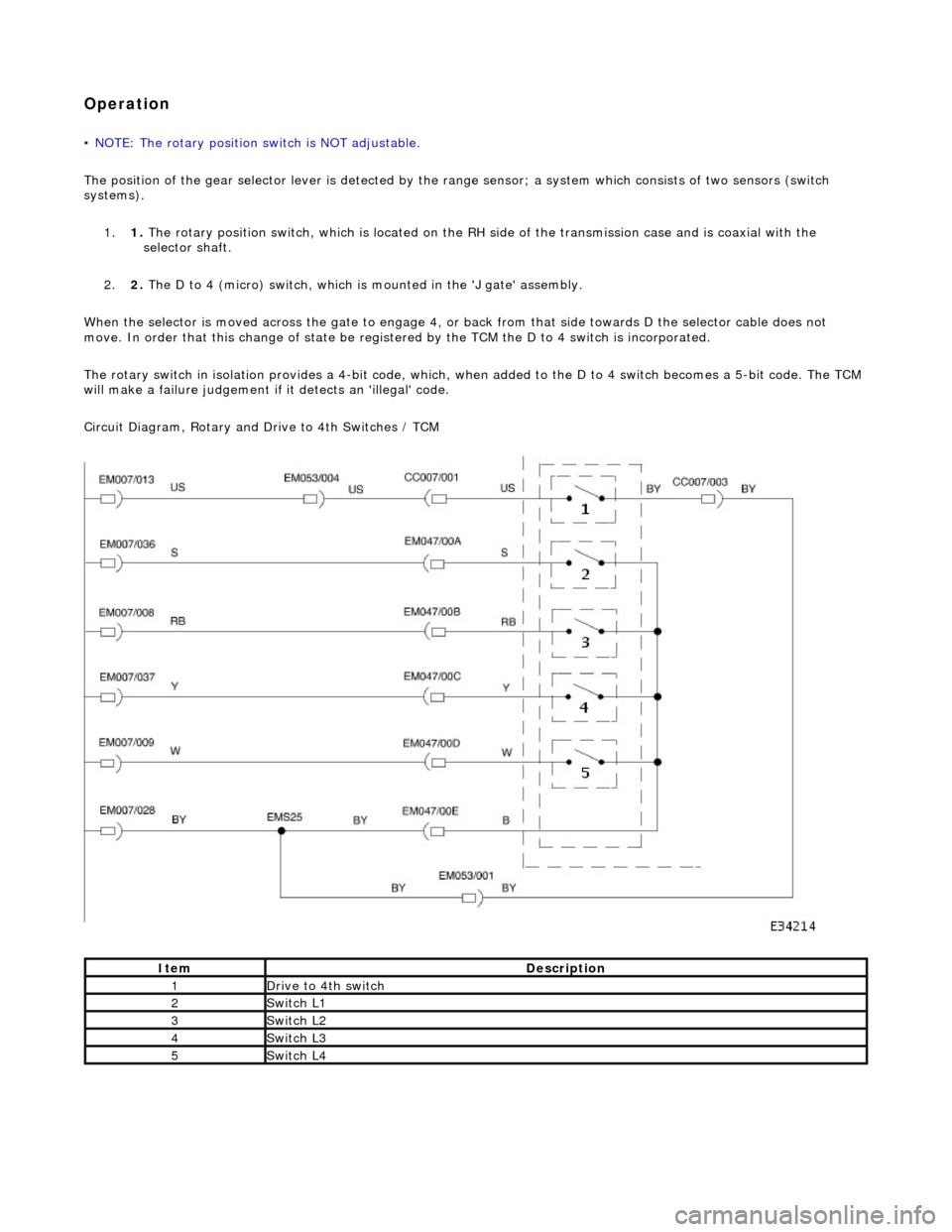
The position of the gear selector lever is detected by the range sensor; a system which consists of two sensors (switch
systems). 1. 1. The rotary position switch, which is located on the RH side of the transmission case and is coaxial with the
selector shaft.
2. 2. The D to 4 (micro) switch, which is mounted in the 'J gate' assembly.
When the selector is moved across the ga te to engage 4, or back from that side towards D the selector cable does not
move. In order that this change of state be registered by the TCM the D to 4 switch is incorporated.
The rotary switch in isolation provides a 4-bit code, which, when added to the D to 4 switch becomes a 5-bit code. The TCM
will make a failure judgement if it detects an 'illegal' code.
Circuit Diagram, Rotary and Drive to 4th Switches / TCM
ItemDescription
1Drive to 4th switch
2Switch L1
3Switch L2
4Switch L3
5Switch L4
Page 1469 of 2490
Automatic Transmission/Transaxle External Controls - 4.0L NA V8 -
AJ27/3.2L NA V8 - AJ26 - External Controls
Diagnosis and Testing
Symptom Chart
Symptom Chart
Pinpoint test A: P0706
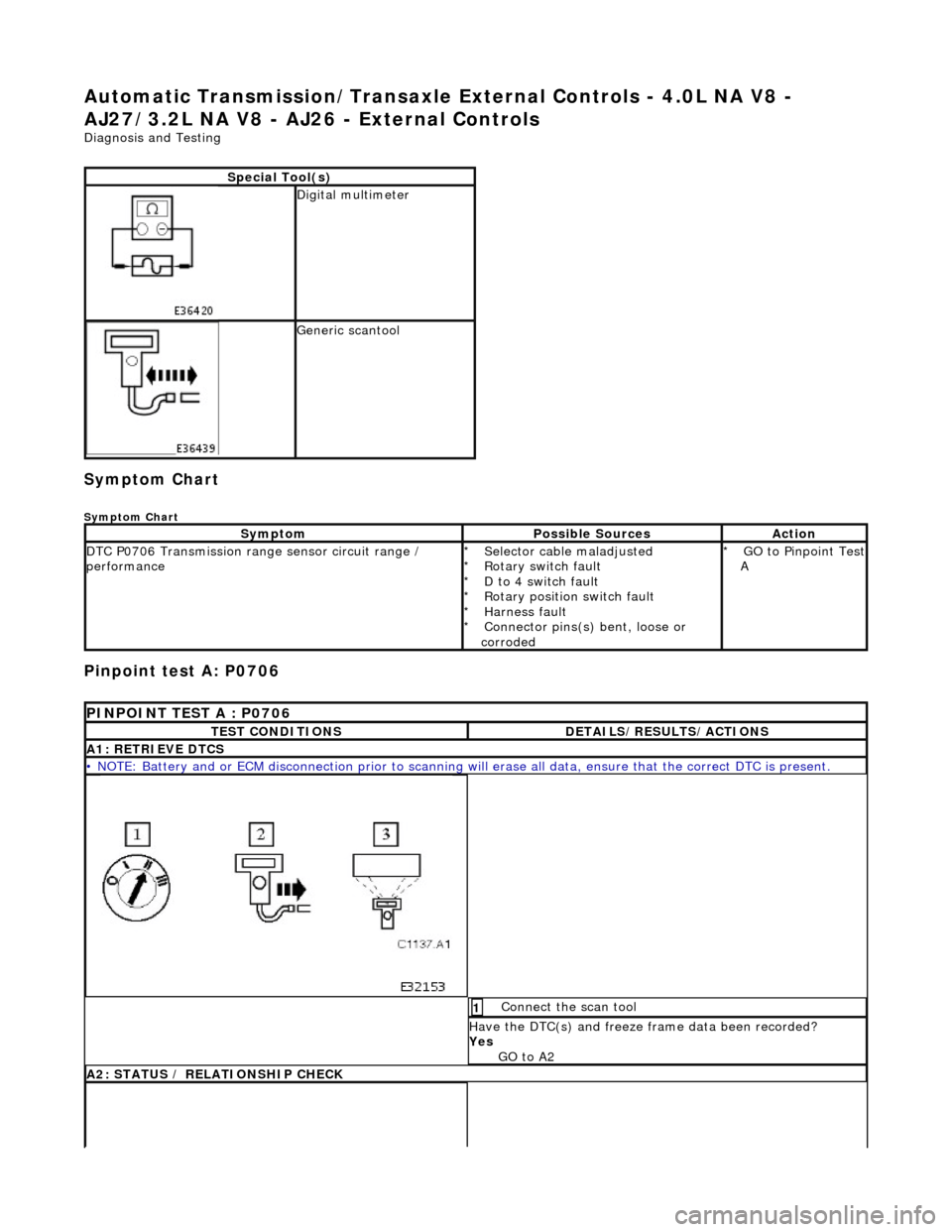
Special Tool(s)
Digital multimeter
Generic scantool
SymptomPossible SourcesAction
DTC P0706 Transmission range sensor circuit range /
performanceSelector cable maladjusted
Rotary switch fault
D to 4 switch fault
Rotary position switch fault
Harness fault
Connector pins(s) bent, loose or
corroded
*
*
*
*
*
*GO to Pinpoint Test A
*
PINPOINT TEST A : P0706
TEST CONDITIONSDETAILS/RESULTS/ACTIONS
A1: RETRIEVE DTCS
• NOTE: Battery and or ECM disconnection prior to scanning wi
ll erase all data, ensure that the correct DTC is present.
Connect the scan tool 1
Have the DTC(s) and freeze frame data been recorded?
Yes GO to A2
A2: STATUS / RELATIONSHIP CHECK
Page 1505 of 2490
Shift Selection and Gear Position
Symptom Chart
Pinpoint test A: P0705
Loose selector disc seal
*
SymptomPossible SourcesAction
DTC P0705 Transmission range sensor circuit
malfunctionSelector cable maladjusted
Linear switch maladjusted
Linear position switch fault
Harness fault
Connector pins(s) bent, loose or
corroded
*
*
*
*
*GO to Pinpoint Test
A
*
PINPOINT TEST A : P0705
TEST CONDITIONSDETAILS/RESULTS/ACTIONS
A1: RETRIEVE DTCS
• NOTE: Battery and or ECM disconnection prior to scanning wi
ll erase all data, ensure that the correct DTC is present.
Connect the scan tool 1
Have the DTC(s) and freeze frame data been recorded?
Yes GO to A2
A2: STATUS / RELATIONSHIP CHECK
Move the selector lever sl owly from P to 2 and back,
noting the illumination / positi on relationship as follows: 1
Does state illumination match the lever position in each
direction of travel?
Yes
GO to A4
No GO to A3
No With lever at D (when moving from 2 to P ) is 3 or 4
illuminated?
Yes GO to A3
Page 1522 of 2490
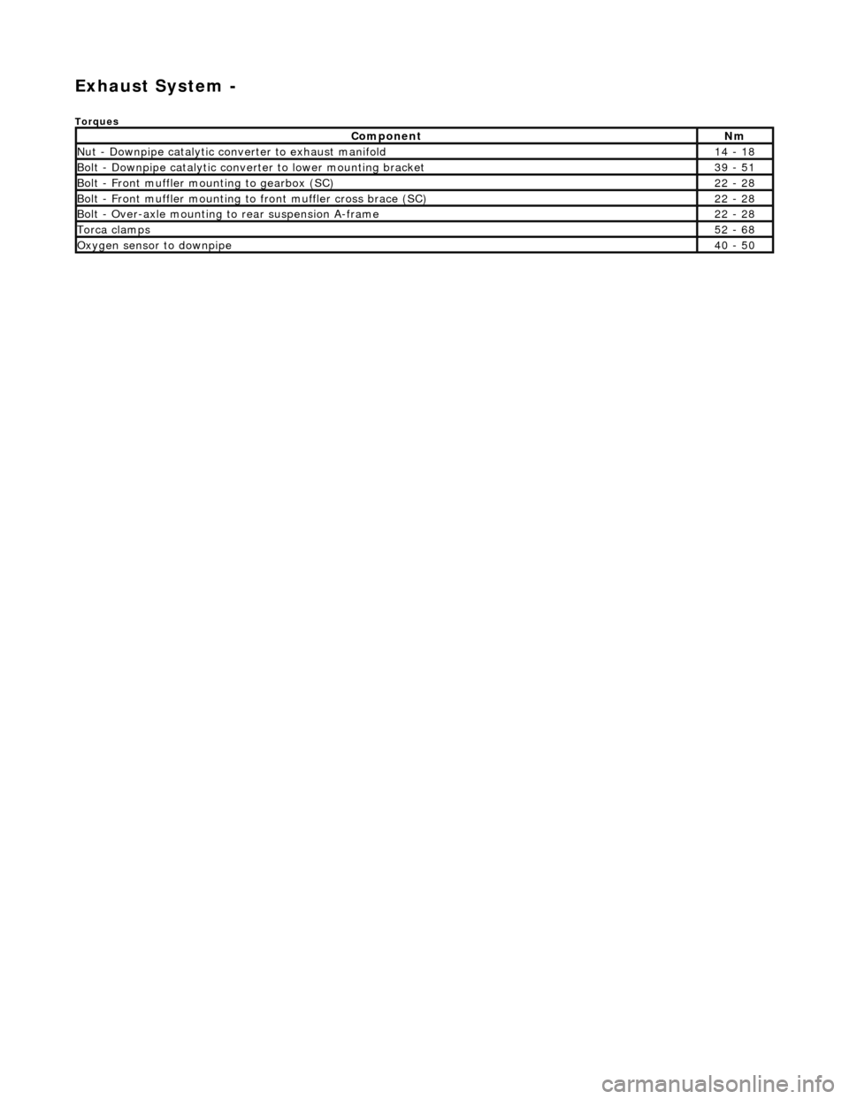
Exhaust System -
Torques
ComponentNm
Nut - Downpipe catalytic converter to exhaust manifold14 - 18
Bolt - Downpipe catalytic converter to lower mounting bracket39 - 51
Bolt - Front muffler mounting to gearbox (SC)22 - 28
Bolt - Front muffler mounting to front muffler cross brace (SC)22 - 28
Bolt - Over-axle mounting to rear suspension A-frame22 - 28
Torca clamps52 - 68
Oxygen sensor to downpipe40 - 50
Page 1525 of 2490
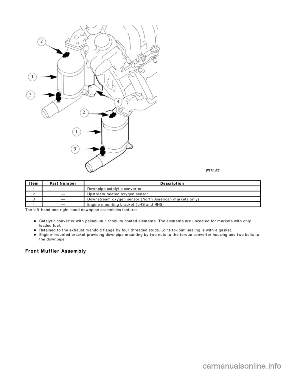
The left-hand and right-hand do wnpipe assemblies feature:
Catalytic converter with palladium / rhodium coated elem ents. The elements are uncoated for markets with only
leaded fuel.
Retained to the exhaust manifold flange by four thread ed studs. Joint-to-joint sealing is with a gasket. Engine-mounted bracket providing downpipe mounting by two nuts to the torque converter housing and two bolts to
the downpipe.
Front Muffler Assembly
ItemPart NumberDescription
1—Downpipe catalytic converter
2—Upstream heated oxygen sensor
3—Downstream oxygen sensor (North American markets only)
4—Engine mounting bracket (LHS and RHS)
Page 1528 of 2490
Joints and Clamps
Pipe-to-pipe joints which are slip joints, feature:
Clamping by Torca strap clamp. Indicator rings providing Maximum, Mini mum and Nominal engagement marks.
Oxygen Sensor (O2)
Location
Page 1529 of 2490
Parts List
Operation
ItemPart NumberDescription
1—Heated oxygen sensor (upstream)
2—Oxygen sensor (downstream)
3—Catalytic converter
Page 1530 of 2490
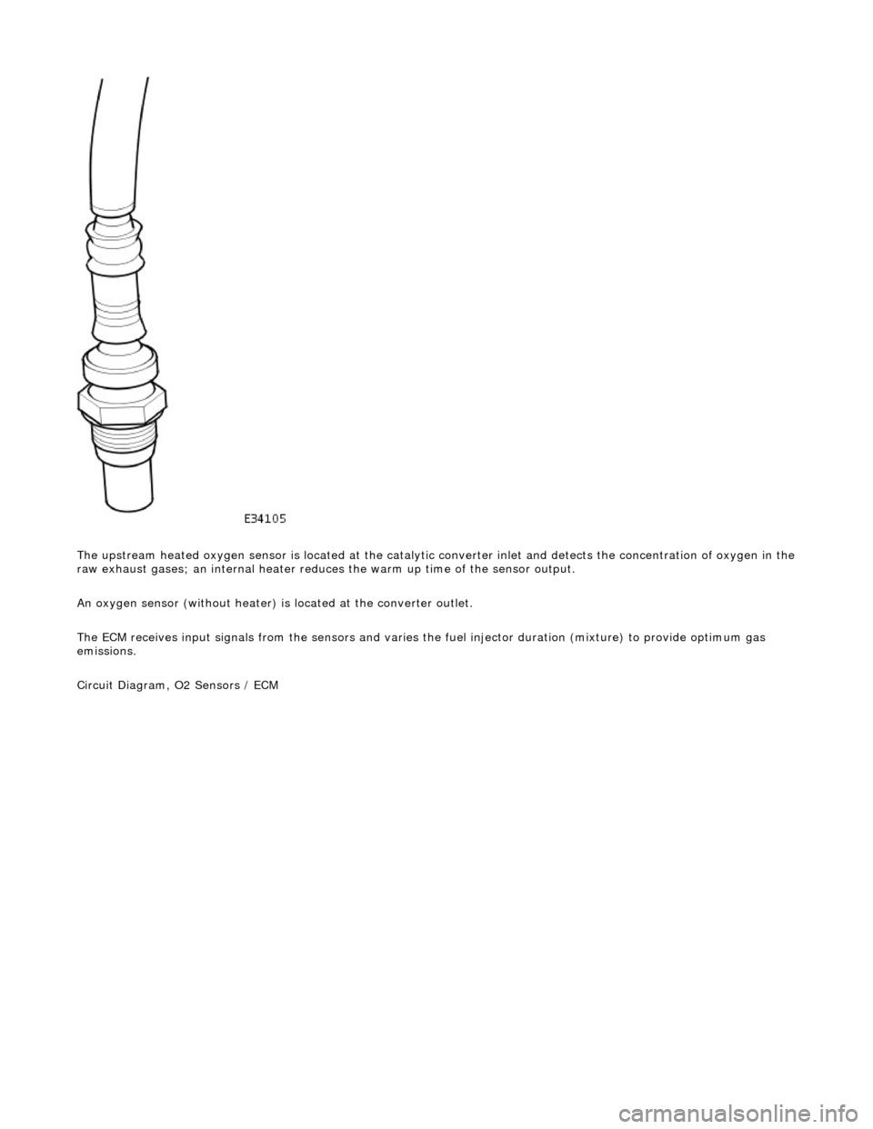
The upstream heated oxygen sensor is located at the catalytic converter inlet and detects the concentration of oxygen in the
raw exhaust gases; an internal heater reduces the warm up time of the sensor output.
An oxygen sensor (without heater) is located at the converter outlet.
The ECM receives input signals from the se nsors and varies the fuel injector duration (mixture) to provide optimum gas
emissions.
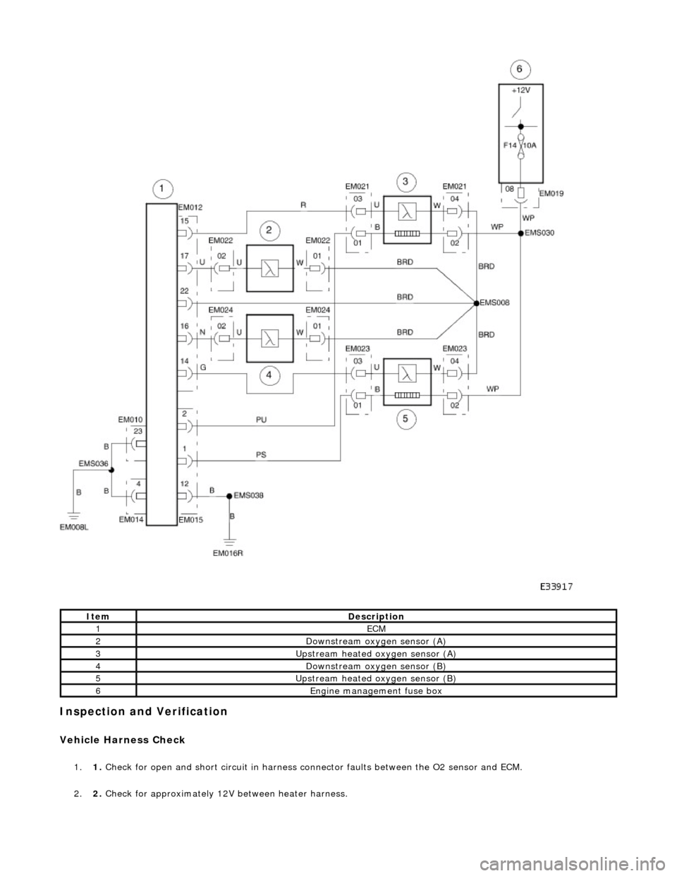
Circuit Diagram, O2 Sensors / ECM
Page 1531 of 2490
Inspection and Verification
Vehicle Harness Check
1.1. Check for open and short circuit in harness conn ector faults between the O2 sensor and ECM.
2. 2. Check for approximately 12V between heater harness.
ItemDescription
1ECM
2Downstream oxygen sensor (A)
3Upstream heated oxygen sensor (A)
4Downstream oxygen sensor (B)
5Upstream heated oxygen sensor (B)
6Engine management fuse box
Page 1532 of 2490
Heater Resistance Check
1.1. Verify that the resistance between the heater term inals is between 4OHM and 10OHM at -20°C to 100°C.
Performance Check
1.1. Run the engine at 2500 RPM for two minutes, to heat up the O2 sensor.
2. 2. Check the voltage of the sensor output: Alternates between less than 0.4V at feed back engine conditions and in
excess of 0.5V, see graph.
These voltages are for reference only.
3. 3. Check that cycle of the upstream se nsor output is in accordance with the appropriate pinpoint test.
4. 4. Check that cycle of the downstream sensor output is in accordance with the appropriate pinpoint test.
