Seat switch JAGUAR X308 1998 2.G Service Manual
[x] Cancel search | Manufacturer: JAGUAR, Model Year: 1998, Model line: X308, Model: JAGUAR X308 1998 2.GPages: 2490, PDF Size: 69.81 MB
Page 2257 of 2490

23. WARNING: ENSURE THAT THE AIR BAG AND
RETAINING CLIPS ARE FULLY SEATED.
Install deployment door.
Install and fully seat deployment door retaining clips in
facia.
Install and fully seat deployment door in clips.
24. Position trunk release switch/housing at facia and connect in-
car sensor to housing.
25. Connect trunk release switch multiplug to facia harness and
install in-car sensor/trunk release switch assembly to facia.
26. Install new major gauge module retaining screw inserts to
facia.
27. Install major gauge module in facia. Refer to 88.20.24.
28. Install instrument panel veneer panel. Refer to 76.47.24.
29. Reposition facia on bench wi th back facing outwards.
30. Position body processor module in facia and install securing
nuts.
Page 2263 of 2490

64.
Position driver stowage bin in facia, install securing screw and fully seat trim.
65. Install trim pad on driver si de lower 'A' post. Refer to
76.13.30.
66. Install driver side unders cuttle. Refer to 76.46.11.
67. Install combined windshield wi per/washer switch and audible
warning speaker assembly. Refer to 86.65.42.
68. Install steering column upper cowl. Refer to 76.46.02.
69. Install steering column lower cowl. Refer to 76.46.03.
70. Install steering wheel. Refer to 211-04.
71. Install driver side airbag. Refer to 76.73.39.
Page 2266 of 2490

Instrument Panel and Console - Instrument Panel Lower Trim Panel
Removal and Installation
Removal
Installation
1.
Turn ignition switch to position 'II.'
2. Motor driver seat fully rearwards.
3. Turn ignition switch to position 'O.'
4. Slacken and remove the four underscuttle securing screws.
5. Remove and discard securing clips from screw locations.
6. Remove underscuttle from vehicle.
1. Fit new securing clips to screw locations.
2. Position and fully seat underscu ttle below fascia and fit and
tighten securing screws.
3. Return driver seat to original position.
Page 2271 of 2490

Instrument Panel and Console - Steering Column Lower Shroud
Removal and Installation
Removal
Installation
1.
Move driver seat fully rearward.
2. Remove battery cover and disconnect ground cable from
battery terminal.Refer to 86.15.19.
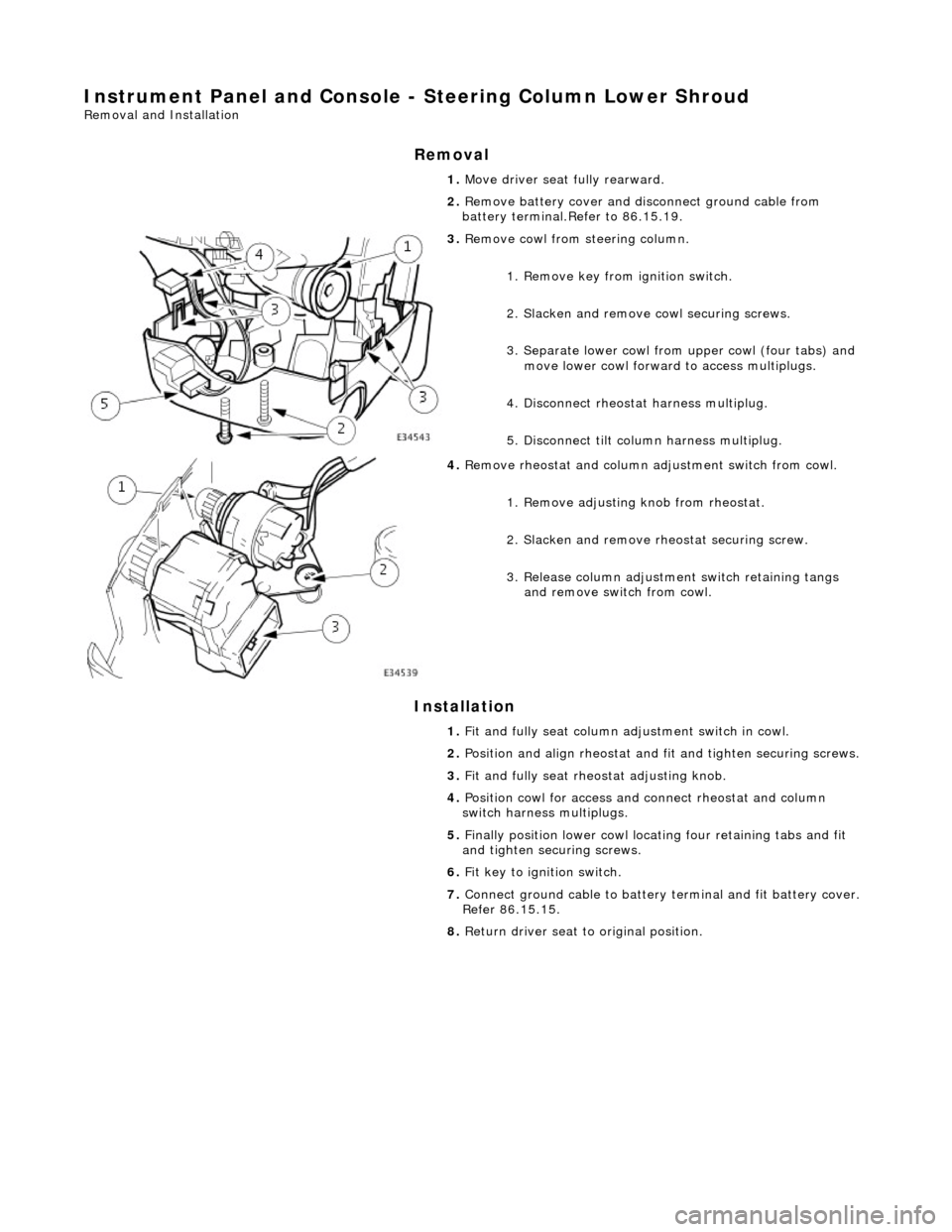
3. Remove cowl from steering column.
1. Remove key from ignition switch.
2. Slacken and remove cowl securing screws.
3. Separate lower cowl from upper cowl (four tabs) and move lower cowl forward to access multiplugs.
4. Disconnect rheostat harness multiplug.
5. Disconnect tilt column harness multiplug.
4. Remove rheostat and column adjustment switch from cowl.
1. Remove adjusting knob from rheostat.
2. Slacken and remove rh eostat securing screw.
3. Release column adjustment switch retaining tangs and remove switch from cowl.
1. Fit and fully seat column ad justment switch in cowl.
2. Position and align rheostat and fit and tighten securing screws.
3. Fit and fully seat rheo stat adjusting knob.
4. Position cowl for access and connect rheostat and column
switch harness multiplugs.
5. Finally position lower cowl locating four retaining tabs and fit
and tighten securing screws.
6. Fit key to ignition switch.
7. Connect ground cable to battery terminal and fit battery cover.
Refer 86.15.15.
8. Return driver seat to original position.
Page 2288 of 2490

Installation
7. Disconnect lock barrel link rod.
8. Disconnect lock motor link rod.
9. Withdraw lock assembly from trunk , release trunk open
switch retaining tang and remove switch from lock assembly.
1. Fit and fully seat trunk open switch to lock assembly.
2. Position lock assembly in trunk and connect lock barrel and
Page 2289 of 2490

lock motor link rods.
3.
Fit and tighten lock assembly securing bolt.
4. Connect lock switch multiplug and install in mounting clip.
5. Reposition trunk lid liner and secure with new fasteners.
6. Position lock finisher and fi t and tighten securing bolts.
7. Fit and fully seat covers over finisher securing bolts.
8. Fit trunk light. Refer to 86.45.16.
Page 2295 of 2490

Installation
7. Disconnect lock barrel link rod.
8. Disconnect lock motor link rod.
9. Withdraw lock assembly from trunk , release trunk open
switch retaining tang and remove switch from lock assembly.
1. Install and fully seat trunk open switch to lock assembly.
2. Position lock assembly in trunk and connect lock barrel and
Page 2336 of 2490

Installation
1. Synchronise control module gears. Refer to 76.82.48.
2. Exercising care to avoid da maging edge, lower front of
headlining for access.
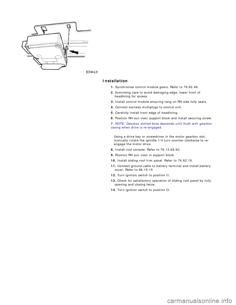
3. Install control module ensuring tang on RH side fully seats.
4. Connect harness multiplugs to control unit.
5. Carefully install front edge of headlining.
6. Position RH sun visor support bl ock and install securing screw.
7. NOTE: Gearbox slotted boss descends until flush with gearbox
casing when drive is re-engaged.
Using a drive key or screwdriver in the motor gearbox slot,
manually rotate the spindle 1/4 turn counter-clockwise to re-
engage the motor drive.
8. Install roof console. Refer to 76.13.69.90.
9. Position RH sun visor in support block.
10. Install sliding roof trim panel. Refer to 76.82.19.
11. Connect ground cable to batter y terminal and install battery
cover. Refer to 86.15.15.
12. Turn ignition switch to position II.
13. Check for satisfactory operation of sliding roof panel by fully
opening and closing twice.
14. Turn ignition switch to position O.
Page 2339 of 2490

Roof Opening Panel - Roof Opening Panel Shield
Removal and Installation
Removal
Installation
1. Turn ignition switch to position II.
2. Open sliding roof to fully tilted position.
3. Turn ignition switch to po sition O and remove key.
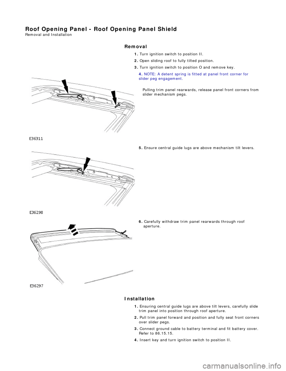
4. NOTE: A detent spring is fitt ed at panel front corner for
slider peg engagement.
Pulling trim panel rearwards, release panel front corners from
slider mechanism pegs.
5. Ensure central guide lugs are above mechanism tilt levers.
6. Carefully withdraw trim panel rearwards through roof
aperture.
1. Ensuring central guide lugs are ab ove tilt levers, carefully slide
trim panel into position through roof aperture.
2. Pull trim panel forward and positi on and fully seat front corners
over slider pegs.
3. Connect ground cable to battery terminal and fit battery cover.
Refer to 86.15.15.
4. Insert key and turn ignition switch to position II.
Page 2341 of 2490

Roof Opening Panel - Roof Opening Panel Trim
Removal and Installation
Removal
Installation
1.
Remove sliding roof trim panel for access. Refer to 76.82.19.
2. Turn ignition switch to position II.
3. Fully open sliding roof panel.
4. Turn ignition switch to O and remove key.
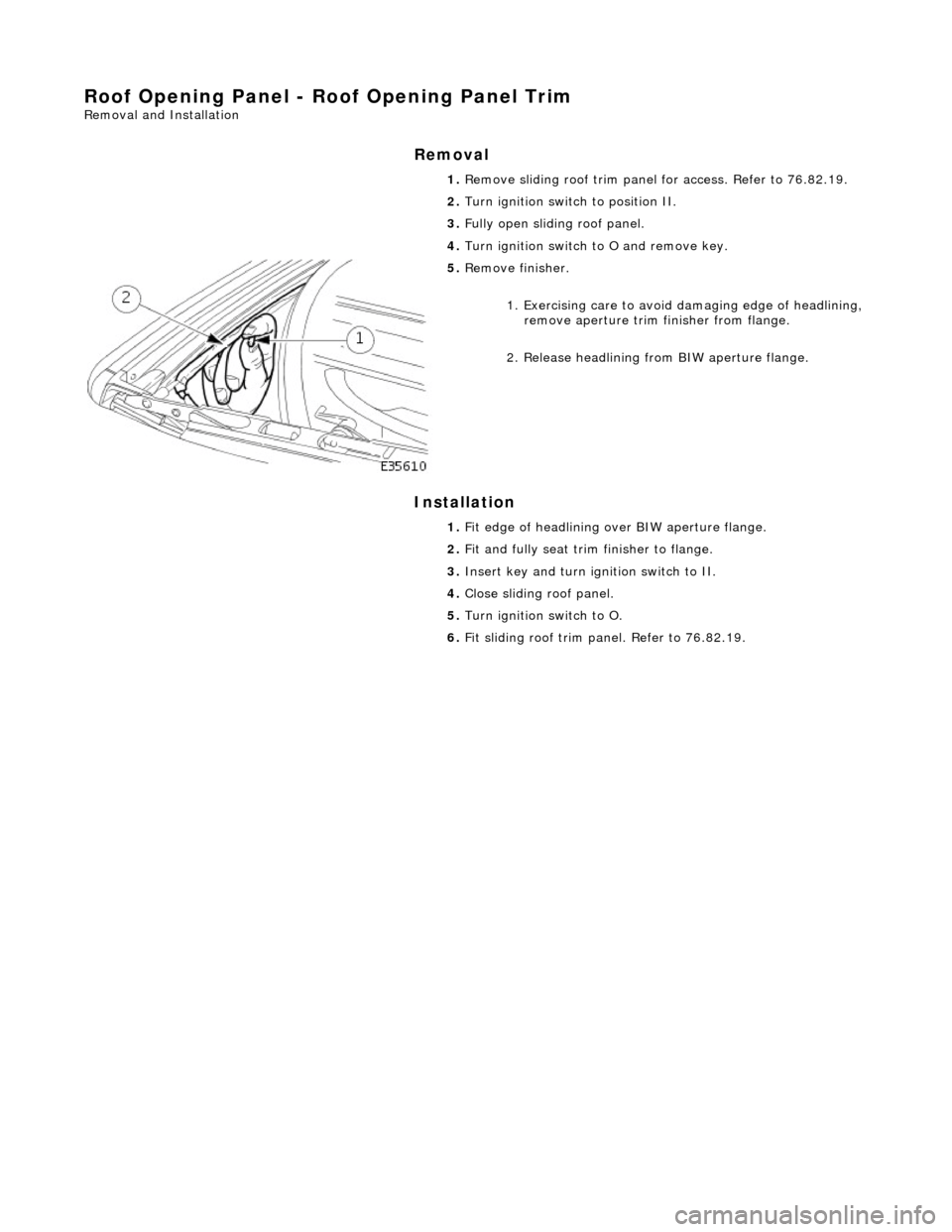
5. Remove finisher.
1. Exercising care to avoid damaging edge of headlining,
remove aperture trim finisher from flange.
2. Release headlining from BIW aperture flange.
1. Fit edge of headlining over BIW aperture flange.
2. Fit and fully seat trim finisher to flange.
3. Insert key and turn ig nition switch to II.
4. Close sliding roof panel.
5. Turn ignition switch to O.
6. Fit sliding roof trim panel. Refer to 76.82.19.