Seat switch JAGUAR X308 1998 2.G Workshop Manual
[x] Cancel search | Manufacturer: JAGUAR, Model Year: 1998, Model line: X308, Model: JAGUAR X308 1998 2.GPages: 2490, PDF Size: 69.81 MB
Page 30 of 2490

501‐10: Seating
Specificatio
n
Description and Operation
Seats
Removal and Installation
Front Seat (76.70.01)
Front Seat Backrest (76.70.06)
Front Seat Backrest Cover (76.70.15)
Front Seat Backrest Heater Mat (86.75.14)
Front Seat Backrest Trim Panel (76.70.03)
Front Seat Cushion (76.70.11)
Front Seat Cushion Cover (76.70.33)
Front Sea
t Cushion Heater Mat (86.75.13)
Front Seat Head Restraint (76.70.14)
Front Seat Head Restraint Motor (86.75.17)
Front Seat Recliner Motor (86.75.04)
Front Seat Track (76.70.20)
Front Seat Track Motor (86.75.33)
Lumbar Motor (86.75.12)
Rear Seat Armrest (76.70.39)
Rear Seat Backrest (76.70.38)
Rear Seat Backrest Cover (76.70.48) (78.90.12)
Rear Seat Backrest Heater Mat (86.75.35)
Rear Seat Cushio
n (76.70.37)
Rear Seat Cushion Cover (76.70.47)
Rear Seat Cushion Heater Mat (86.75.37)
Rear Seat Head Restraint (76.70.56)
Rear Seat Track
Seat Control Switch (86.75.23)
501‐11: Glass, Frames and Mechanisms
Description and Operation
Glass, Fra
mes and Mechanisms
Removal and Installation
Door Window Control Switch Bulb (86.46.12)
Front Door Window Glass (76.31.01)
Front Door Window Glass Weatherstrip (76.40.28)
Page 47 of 2490
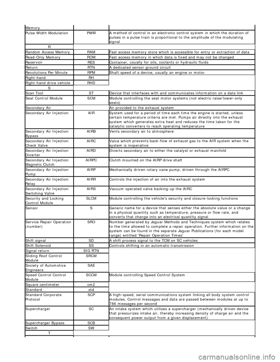
Mem
ory
Pulse Width ModulationPW
M
A
method of control in an electronic co
ntrol system in which the duration of
pulses in a pulse train is proportional to the amplitude of the modulating
signal
R
Ran
dom Access Memory
RAMF
ast access memory store which is accessible for entry or extraction of data
Re
ad-Only Memory
RO
M
F
ast access memory in which data
is fixed and may not be changed
Re
servoir
RESContaine
r, usually for oils,
coolants or hydraulic fluids
Re
turn
RTNA
dedicated sensor ground circuit
R
evolutions Per Minute
RP
M
Shaft speed o
f a device, us
ually an engine or motor
R
ight-hand
RH
Right-hand drive veh
icle
RHD
S
Scan T
ool
STDe
vice that interfaces with and comm
unicates information on a data link
Se
at Control Module
SCMModule
controlling the seat motor systems (not electric raise/lower-only
seats)
Secon
dary Air
Air pro
vided to the exhaust system
Secon
dary Air Injection
AIRSy
stem used for a period of time each
time the engine is started, unless
certain temperature criter ia are met. Pumps air directly into the exhaust
system which generates extra heat and reduces the time taken for the
catalytic converters to reach operating temperature
Secon
dary Air Injection
Bypass
AIRBVents secon
dary air to atmosphere
Secon
dary Air Injection
Check Valve
AIRCValve wh
ich prevents back-flow of exhaust gas to the AIR system when the
system is inoperative
Secon
dary Air Injection
Diverter
AIRDD
iverts secondary air to either
the catalyst or exhaust manifold
Secon
dary Air Injection
Magnetic Clutch
AIRP
C
Clu
tch mounted on the AIRP drive shaft
Secon
dary Air Injection
Pump
AIRPMe
chanically driven rotary vane
pump, driven through the AIRPC
Secon
dary Air Injection
Relay
AIRRCont
rols the injection of air into the exhaust system
Secon
dary Air Injection
Switchin
g Va
lve
AIRSV
acuum operated valve backing-up the AIRC
Secu
rity and Locking
Control Module
SLCMModul
e controlling the vehicle's security and closure-locking functions
SensorSGeneri
c name for a device
that senses either the absolute value or a change
in a physical quantity su ch as temperature, pressure or flow rate, and
converts that change into an electrical quantity signal
Servic
e Repair Operation
(number)
SRONu
mber generated by Jaguar Methods
and Techniques system which relates
to the time allowed to complete a repair operation. Further information on the
system can be found in the separate Jaguar Publications (for each model
range) entitled 'Repair Operation Times'
Shif
t signal
SDA
shift process signal to the TCM on SC vehicles
Shif
t Solenoid
SSControls shi
fting in an automatic transmission
Si
gnal return
SIG RTN
Slidin
g Roof Control
Module
SRCM
Society of Automotive
Engineers
SAE
Speed
Control Control
Module
SCCMModule con
trolling Speed Control System
Square c
entimeter
cm
2
Stan
dard
std
Stan
dard Corporate
Protocol
SCPA
high-speed, serial communications system linking all body system control
modules. Control messages and data ar e passed between modules at up to
786 messages per second
SuperchargerSCAn in
take system which utilizes a supercharger (mechanically driven device
that pressurizes intake air, thereby in creasing density of charge air and the
consequent power output from a given displacement)
Supercharger
Bypass
SCB
SwitchSW
T
Page 396 of 2490
Parking Brake and Actuation - P
arking Brake Control
Re
mo
val and Installation
Remov
a
l
W
A
RNING: BRAKE DUST, IF INHALED CAN DAMAGE YOUR
HEALTH. ALWAYS REMOVE BRAKE DUST USING A VACUUM
BRUSH. DO NOT USE A COMPRESSED-AIR LINE TO DISPERSE BRAKE DUST INTO THE ATMOSPHERE.
CAUTION: Replacement of nuts and bolts: Various thread-locking devices are used on nuts and bolts throughout the
vehicle. These devices restrict the number of times a nut or bolt can be used. See section 100-00 for information.
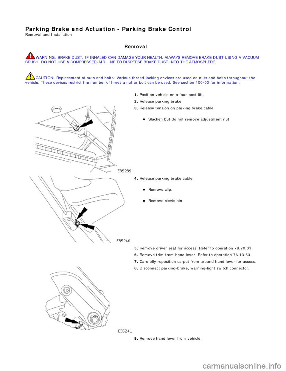
1. Position vehi cl
e on a four-post lift.
2. Release parking brake.
3. Releas
e tension on parking brake cable.
Slacken bu
t do not remove adjustment nut.
4. Releas
e parking brake cable.
Remo
ve clip.
Re
mo
ve clevis pin.
5. Remove driver seat for access . Refer to operation 76.70.01.
6. Remove trim from hand lever. Refer to operation 76.13.63.
7. Carefully reposition carpet from around hand lever for access.
8. Disconnect park ing-br
ake, warning-light switch connector.
9. Remove hand lever from vehicle.
Page 398 of 2490
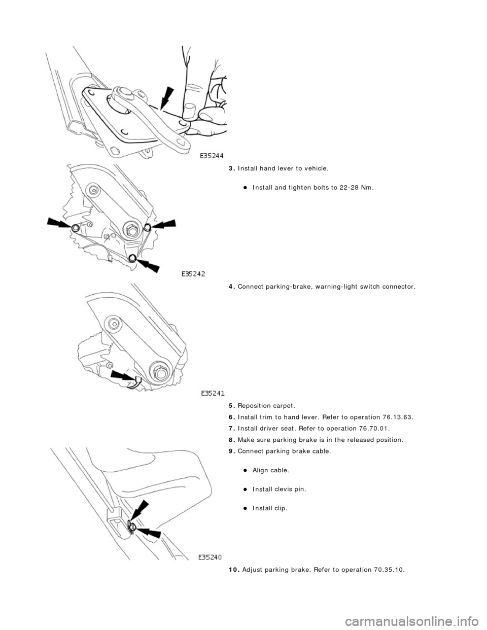
3. Instal
l hand lever to vehicle.
Install and tighten bolts to 2
2-28 Nm.
4. Connect park
ing-brake, warnin
g-light switch connector.
5. Reposition carpet.
6. Install trim to hand lever. Refer to operation 76.13.63.
7. Install driver seat. Refer to operation 76.70.01.
8. Make sure parking brake is in the released position.
9. Connect p a
rking brake cable.
Align ca
ble
.
Inst
al
l clevis pin.
Inst
al
l clip.
10. Adjust parking brake. Refer to operation 70.35.10.
Page 403 of 2490
Parking Brake and Ac
tuat
ion - Parking Brake Warn ing Indicator Switch
Re
moval and Installation
Remov
al
Installation
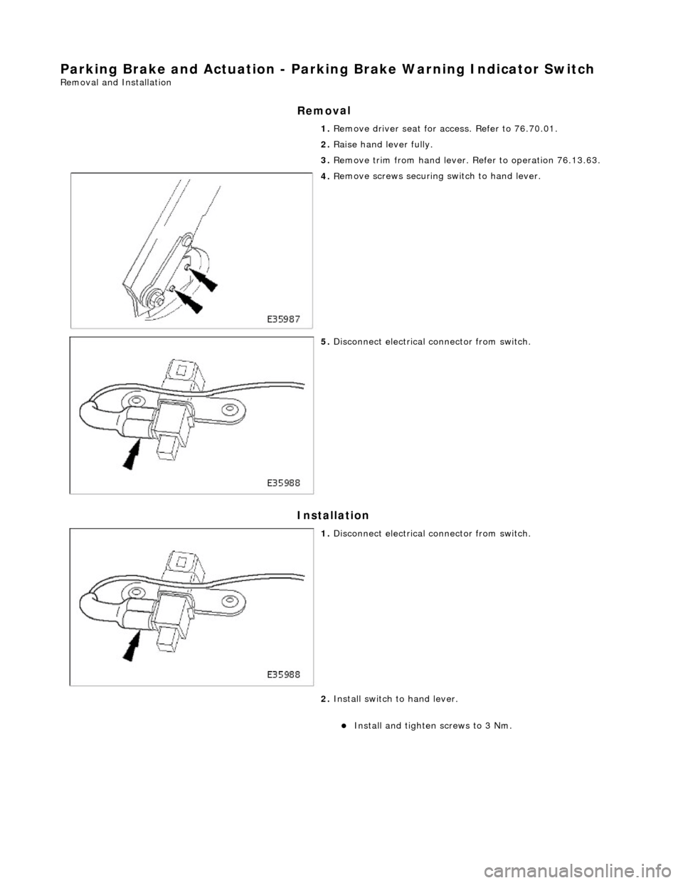
1. R
emove driver seat for access. Refer to 76.70.01.
2. Raise hand lever fully.
3. Remove trim from hand lever. Refer to operation 76.13.63.
4. R
emove screws securing
switch to hand lever.
5. Di
sconnect electrical connector from switch.
1. Di
sconnect electrical connector from switch.
2. Install switch to hand lever.
Install and tigh
ten
screws to 3 Nm.
Page 954 of 2490
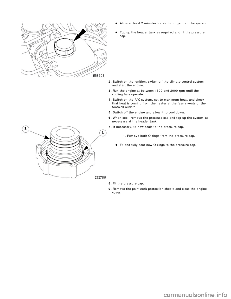
Allow at least 2 minutes f
or ai
r to purge from the system.
Top up the he
ader tank as re
quired and fit the pressure
cap.
2. Switch on the ignition, switch off the climate control system
and start the engine.
3. Run the engine at between 1500 and 2000 rpm until the
cooling fans operate.
4. Switch on the A/C system, set to maximum heat, and check
that heat is coming from the heat er at the fascia vents or the
footwell outlets.
5. Switch off the engine and allow it to cool down.
6. When cool, remove the pressure cap and top up the system as
necessary at the header tank.
7. If n e
cessary, fit new seals to the pressure cap.
1. Remove both O-rings from the pressure cap.
Fit and
fully seat new O-rings to the pressure cap.
8. Fit the pressure cap.
9. Remove the paintwork protection sheets and close the engine
cover.
Page 957 of 2490
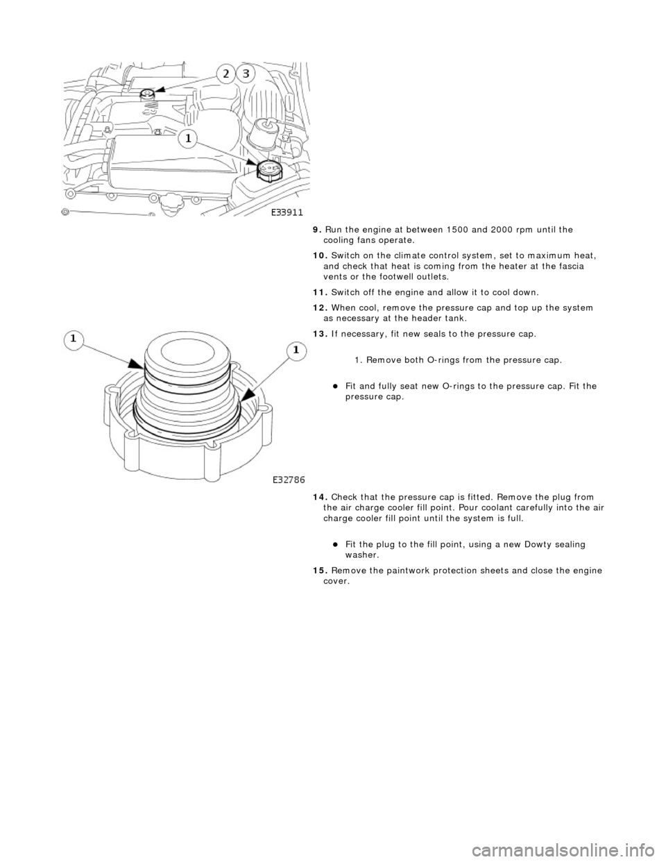
9.
R
un the engine at between 1500 and 2000 rpm until the
cooling fans operate.
10. Switch on the climate control system, set to maximum heat,
and check that heat is coming from the heater at the fascia
vents or the footwell outlets.
11. Switch off the engine and allow it to cool down.
12. When cool, remove the pressure cap and top up the system
as necessary at the header tank.
13
.
If necessary, fit new seals to the pressure cap.
1. Remove both O-rings from the pressure cap.
Fit and
fully seat new O-rings
to the pressure cap. Fit the
pressure cap.
14. Check that the pressure cap is fitted. Remove the plug from
the air charge cooler fill point. Pour coolant carefully into the air
charge cooler fill point until the system is full.
F
it the plug to the fill poin
t, using a new Dowty sealing
washer.
15. Remove the paintwork protection sheets and close the engine
cover.
Page 1803 of 2490
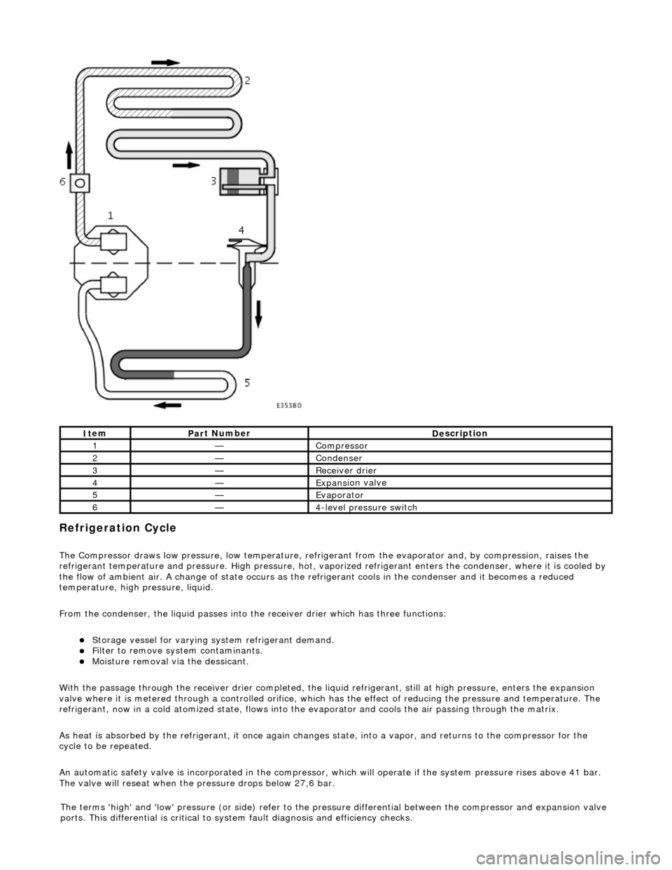
Refrigeration Cycle
The Compressor draws low pressure, lo
w te
mperature, refrigerant from the evaporat or and, by compression, raises the
refrigerant temperature and pressure. High pressure, hot, vaporized refr igerant enters the condenser, where it is cooled by
the flow of ambient air. A change of state occurs as the refrigerant cools in the condense r and it becomes a reduced
temperature, high pressure, liquid.
From the condenser, the liquid passes into the receiver drier which has three functions:
Storage vessel
for varying sy
stem refrigerant demand.
F
ilter to remove sy
stem contaminants.
Mo
isture removal via the dessicant.
With the passage through the receiver drie r completed, the liquid refrigerant, still at high pressure, enters the expansion
valve where it is metered through a contro lled orifice, which has the effect of reducing the pres sure and temperature. The
refrigerant, now in a cold atomized st ate, flows into the evaporator and cools the air passing through the matrix.
As heat is absorbed by the refrigerant, it once again changes state, into a vapor, and returns to the compressor for the
cycle to be repeated.
An automatic safety valve is incorporated in the compressor, which will operate if the system pressure rises above 41 bar.
The valve will reseat when the pressure drops below 27,6 bar.
It
em
Par
t Number
De
scription
1—Compre
ssor
2—Conden
ser
3—Re
ceiver drier
4—Expans
ion valve
5—Evaporator
6—4
-level pressure switch
The terms 'high' and 'low'
pressure (or si
de) refer to the pres sure differential betw een the compressor and expansion valve
ports. This differential is critical to sy stem fault diagnosis and efficiency checks.
Page 1853 of 2490
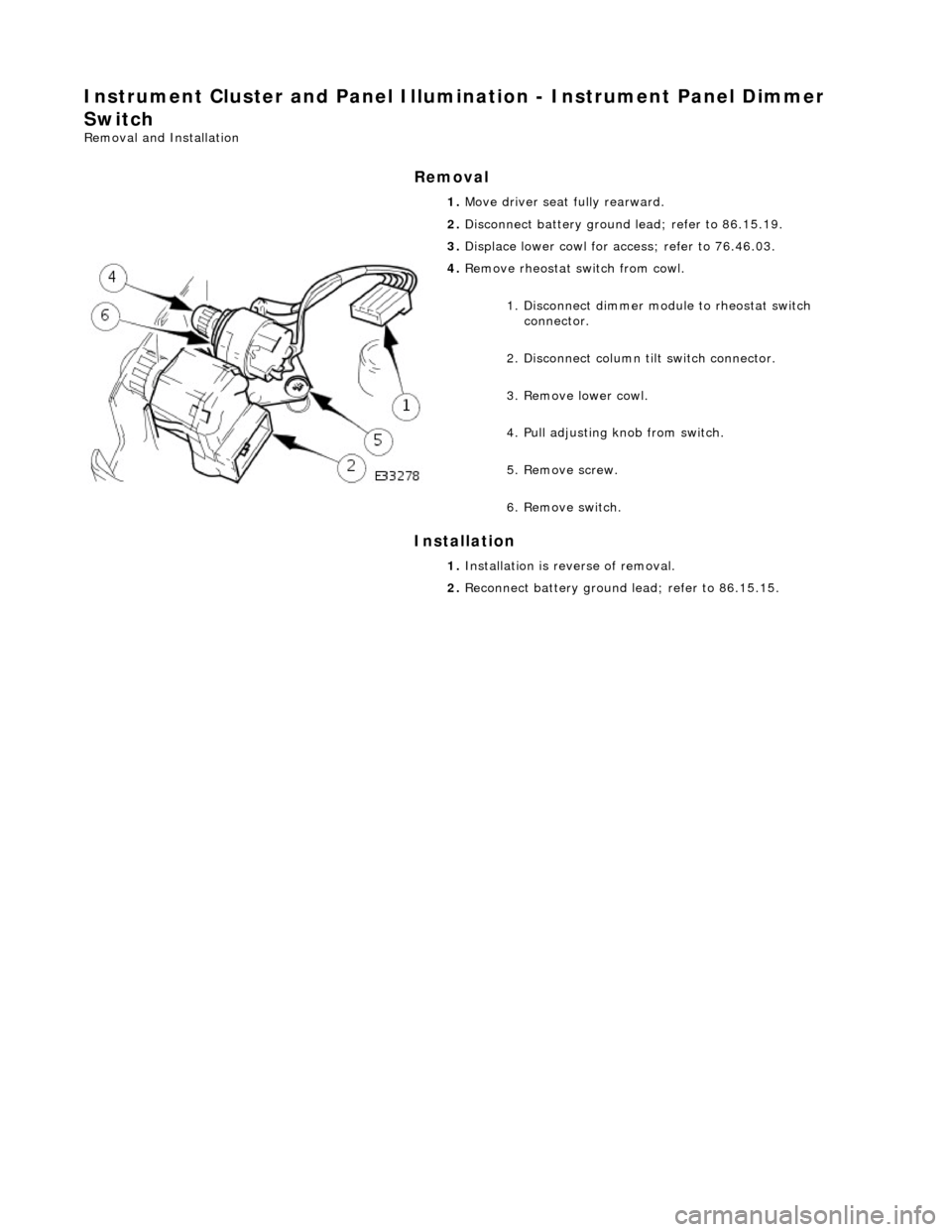
Instrument Cluster and Panel Illumination - Instrument Panel Dimmer
Switch
Removal and Installation
Removal
Installation
1.
Move driver seat fully rearward.
2. Disconnect battery ground lead; refer to 86.15.19.
3. Displace lower cowl for access; refer to 76.46.03.
4. Remove rheostat sw itch from cowl.
1. Disconnect dimmer module to rheostat switch connector.
2. Disconnect column tilt switch connector.
3. Remove lower cowl.
4. Pull adjusting knob from switch.
5. Remove screw.
6. Remove switch.
1. Installation is reverse of removal.
2. Reconnect battery ground lead; refer to 86.15.15.
Page 1858 of 2490
In
stallation
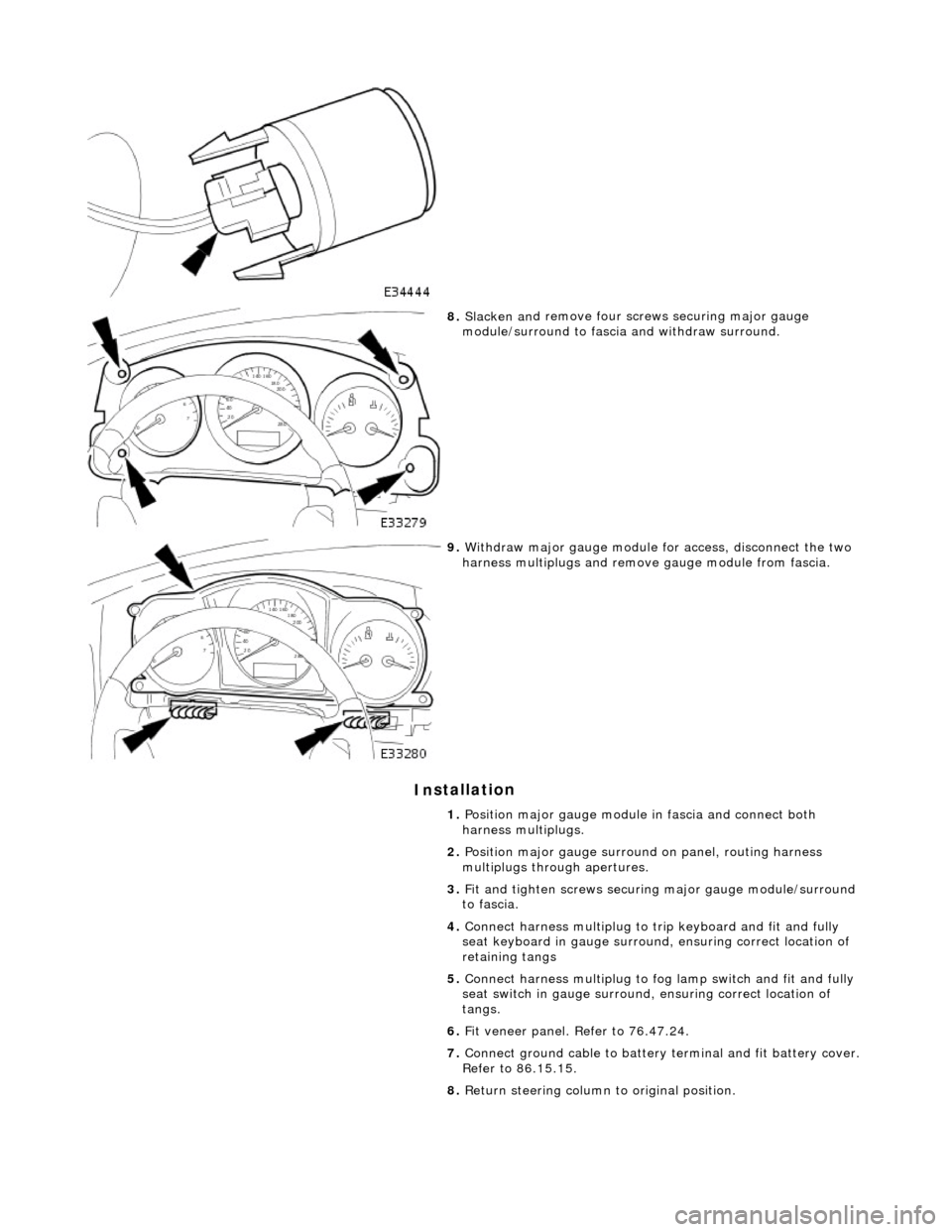
8.
Slac ken an
d remove four screws securing major gauge
module/surround to fascia and withdraw surround.
9. With draw major gau
ge module fo
r access, disconnect the two
harness multiplugs and remove gauge module from fascia.
1. Position major gauge module in fascia and connect both
harness multiplugs.
2. Position major gauge surround on panel, routing harness
multiplugs through apertures.
3. Fit and tighten screws securing major gauge module/surround
to fascia.
4. Connect harness multiplug to tr ip keyboard and fit and fully
seat keyboard in gauge surround, ensuring correct location of
retaining tangs
5. Connect harness multiplug to fog lamp switch and fit and fully
seat switch in gaug e surround, ensuring correct location of
tangs.
6. Fit veneer panel. Refer to 76.47.24.
7. Connect ground cable to battery terminal and fit battery cover.
Refer to 86.15.15.
8. Return steering column to original position.