evaporative JAGUAR X308 1998 2.G Service Manual
[x] Cancel search | Manufacturer: JAGUAR, Model Year: 1998, Model line: X308, Model: JAGUAR X308 1998 2.GPages: 2490, PDF Size: 69.81 MB
Page 1201 of 2490

leak
/blockage
EVAP valve failure
P0444Evaporati
ve emissions system
(EVAP) valve circuit open circuit
EVAP t
o ECM drive circuit open
circuit or high resistance
EVAP failu
re
F
or evaporative emissions pinpoint
tests,
REFER to Section 303
-1
3 Evaporative
Emiss
ions
.
P0445Evaporati
ve emissions system
(EVAP) valve circuit short circuit
E
VAP to ECM drive circuit short
circuit to ground
EVAP failu
re
F
or evaporative emissions pinpoint
tests,
REFER to Section 303
-1
3 Evaporative
Emiss
ions
.
P0447Cani
ster close valve (CCV) circuit
open circuit
CCV to ECM
drive circuit open
circuit, high resi stance or short
circuit to ground
EVAP failu
re
F
or evaporative emissions pinpoint
tests,
REFER to Section 303
-1
3 Evaporative
Emiss
ions
.
P0448Cani
ster close valve (CCV) circuit
short circuit
CCV to
ECM drive circuit short
circuit to high voltage
CCV failure
F
or evaporative emissions pinpoint
tests,
REFER to Section 303
-1
3 Evaporative
Emiss
ions
.
P0452F
uel tank pressure (FTP) sensor
circuit low voltage
FTP
sensor disconnected
FTP
sensor to ECM sense circuit
open circuit or short circuit to
ground
FTP sen
sor to ECM power supply
circuit open circuit or short circuit
to ground
F
TP sensor failure
F
or evaporative emissions pinpoint
tests,
REFER to Section 303
-1
3 Evaporative
Emiss
ions
.
P0453F
uel tank pressure (FTP) sensor
circuit high voltage
FTP
sensor to ECM signal ground
circuit open circuit
F
TP sensor to ECM wiring (supply,
sense, signal, ground) short circuit
to each other
FTP
sensor to ECM sense circuit
short circuit to high voltage
F
TP sensor failure
F
or evaporative emissions pinpoint
tests,
REFER to Section 303
-1
3 Evaporative
Emiss
ions
.
P0460Fue
l level sense signal
performance
Fue
l level sensor
to instrument
cluster circuits in termittent short or
open circuit
F
uel level sensor failure
Instrument cluster
faul
t (incorrect
fuel level data)
F
or fuel level sensor
circuit tests,
REFER to Section 303
-04
Fuel
Charging and Con
trols
.
P0506Idl
e rpm lower than expected
Ai
r intake blockage
Acce
ssory drive overload
(defective/siezed component)
Thr
ottle valve stuck closed
Throttl
e assembly failure
Chec
k the air intake system.
REFER to Section 303
-1
2 Intake Air
Distribu
tion and Filtering
.
Check t
he accessory drive
components,
REFER to Section 303
-0
5 Accessory
Dr
ive
.
F
or throttle body information,
REFER to Section 303
-04
Fuel
Charging and Con
trols
.
P0507Idle rpm
higher than expected
Inta
ke air leak between MAF
sensor and throttle
Inta
ke air leak between throttle
and engine
Engine
breather leak
Cruis
e (speed) control vacuum
failure
Thr
ottle valve stuck open
Throttl
e assembly failure
Chec
k the air intake system.
REFER to Section 303
-1
2 Intake Air
Distribu
tion and Filtering
.
Chec
k the engine breather system,
REFER to Section 303
-08
Engine
Emissi
on Control
.
F
or cruise (speed) control information,
REFER to Section 310
-03
Speed
Control.
F
or throttle body information,
REFER to Section 303
-04
Fuel
Charging and Con
trols
.
P0560Vehicle voltage
malfunction
ECM battery
power supply open
circuit, high resistance
F
or ECM power supply circuit tests,
GO to Pinpoint Test AD.
.
P0566Cruise (speed) contr
ol
CANCEL
switch ON fault
Cru
ise (speed) control switches
internal steering wheel short circuit
to ground
For cru
ise (speed) control circuit tests,
REFER to Section 310
-03
Speed
Page 1242 of 2490

Diagnostic Monitor Comp
letion
stat
ionery in
D.
WARNING: This should not be attempted without the vehicle
being in a safe area and suitably chocked. Failure to follow this
instruction may result in personal injury.
Without using the Jaguar approved diagnostic system or a scan
tool with system readiness capability, it will not be possible to
confirm when the adaptations are complete, unless P1111,
(system checks complete since last memory clear) is flagged. If
such equipment is not available, ALL the diagnostic monitors
will have to run to enable DTC P1111 to be flagged. In some US
states, this code is a requirem ent for annual emissions tests.
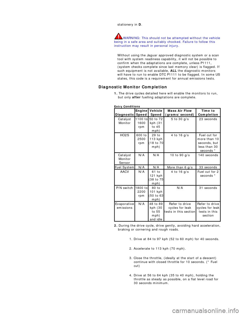
1. The dri v
e cycles detailed here w
ill enable the monitors to run,
but only after fuelling adaptations are complete.
Entry C
onditions
Di
agno
stic
Engine
S p
eed
Ve
h
icle
Speed
Mass Air Flow
(gra ms/sec
ond)
Ti
m
e to
Completion
Catalyst Monitor1 100
to
1600 rpm
50 to
72
kph (31 to 45
mph)
5 to
30 g/s
23
se
conds
HO2S6
00 t
o
2500 rpm
29 to
113 kph
(18 to 70
mph)
4 to
16 g/s
F
u
el cut for
more than 10 seconds, but less than 30 seconds *
Catalyst Monitor SensorN/ AN/A10
to 90 g/s
14
0
seconds
F
u
el System
N/
AN/AMore than 6 g/s33 se
conds
AACVN/
A61 to
121 kph
(38 to 75
mph)
4 to
16 g/s
F
u
el cut for 2
seconds *
P /
N switch
1
800
to
2200 rpm
80 to
101 kph
(50 to 63
mph)
N/ A31 se
conds
Evaporative
em is
sions
N/
A48 to
89
kph (30 to 55
mph)
and idle
R e
fer to drive
cycles for leak
tests in this section
Re
fer to drive
cycles for leak
tests in this section
2. During the drive cycle, drive gent ly, avoiding hard acceleration,
braking or cornering and rough roads.
1. Drive at 84 to 97 kph (52 to 60 mph) for 40 seconds.
2. Accelerate to 113 kph (70 mph).
3. Close the throttle, (ideally at the start of a descent)
continue with closed throttle for 10 seconds. (* Fuel
cut)
4. Drive at 56 to 64 kph (35 to 40 mph), holding the throttle as steady as possib le, on a flat level road for
30 seconds minimum.
Page 1243 of 2490

Drive Cycle for 40 thou leak test
Drive Cycle for 20 thou leak test (2001 my on only)
1. Make sure the "conditions
for ad
aptation" detailed at the start
of this section are met.
1. Avoiding high engine load s, drive the vehicle steadily
between 48 and 89 kph (30 and 55 mph) for 15 to 20
minutes after starting the engine. (Depending on the
amount of fuel vapor gene rated, the test may take
longer than this).
2. Where possible, avoid body roll to minimise fuel movement.
3. If the scan tool being used is able to read TIDs, check
TID 08 in mode 6. If the test has not completed, this
TID will display "0". Any other value indicates that
the test has successfully completed.
4. If the test has not completed, the drive cycle must be repeated.
5. If the scan tool being used is not able to read TIDs, the only way to confirm that the test has run is to
check for P1111 after running the 20 thou test, where
applicable.
1. This test needs to be completed within 50 minutes of starting
the engine from cold. It should be run following the 40 thou
test.
1. Continue driving the vehi cle steadily between 48 and
89 kph, (30 and 55 mph) avoiding high engine loads
for a further 15 minutes.
2. Avoiding excessive fuel movement, bring the vehicle to rest.
3. Allow to idle for two minutes.
4. Provided the vapor conditions are suitable, the test will complete.
5. If the scan tool being used is able to read TIDs, check
TID 06 in mode 6. If the test has not completed, this
TID will display "0". Any other value indicates that
the test has successfully completed.
6. If the test has not completed, the drive cycle must be repeated.
7. Check for DTCs. P1111 will be flagged if all monitors have run.
8. Leak check drive cycles will only normally be necessary if an Evaporative Emissions related DTC is
flagged.
9. Unless P1111 is required for the State inspection, fuelling adaptations will normally be all that is
required for the vehicle to adapt itself and complete
Page 1692 of 2490

Fuel Tank and Lines - Fuel Tank and Li
nes
Description an
d Operation
Fuel Tank
Parts List
The steel fuel tank is located inside the trunk and mounted across the vehicle behind the passenger compartment bulkhead.
The fuel tank is held in posi tion by two retaining straps fi tted to body-mounted brackets.
The fuel tank has an integral non-adjustable fill er pipe and integral breather and vapor pipework.
A single fuel pump is mounted inside the tank on vehicles with normally aspirated engines. For vehicles with supercharged
engines, two pumps are fitted in the tank. Fuel is drawn by the pump(s) from the fuel tank and supplied via the fuel lines
and 70 micron filter to the fuel rails.
The fuel lines run from front-to-rear down the vehicle's left-hand-side.
Ite
m
Part
Number
Descr
iption
1—Fu
el filler latch box
2—Pressure reli
ef pipe, ORVR
(shown) / tank breather pipe on non-ORVR systems
3—Tank grounding
cable
4—Evaporative flan
ge assembly
(ORVR type shown)
5—Trunk elec
trical harne
ss (part of)
6—Fue
l
level sensor
flange/connector
7—Fu
el tank retaining straps
8—F
u
el tank retaining stra
ps adjustable clamps
9—Fu
el tank retaining straps lower brackets
10—Tank vapor outlet pipe to un
derflo
or pipe quick-fit connector
11—F
u
el filler latch bo
x water drain pipe
Page 1693 of 2490

Filler Cap and P
ipe
The fuel
filler cap with bayonet-type fixi
ng is located beneath a remote-release sp ring-latched lid on the rear saddle panel
on the left-hand-side of the vehicle.
Fuel Pum
p
The fu
el pump(s) is energized by an ECM co
ntrolled relay. Fuel is drawn by this pu mp and supplied to the fuel injectors via
the fuel line, filter and fuel rails.
Servicing of the fuel pump re quires fuel tank removal.
Ev
aporative Loss Flange Assembly
The evaporative-loss flan
ge asse
mbly is mounted centrally on top of the tank. The flange assembly consists of a removeable
steel cap which mounts the evaporative emissions system vapor outlet valves and, if applicable, a pressure sensor. The
external electrical supply to th e fuel pump(s) is also made via a connector on the flange.
The flange assembly is fixed to the tank by a locking ring which is turned usin g special tool JD-174. A seal is fitted between
the flange assembly and the tank. Three di fferent flange assemblies are applicable according to the evaporative emission
system fitted to the vehicle. The fl ange size and fixing are identical fo r the three systems, as described.
Removal of the evaporative flange assembly is necessary to gain access to th e fuel pump(s) and other internal components.
To remove the evaporative fl ange assembly the fuel tank must first be removed.
The evaporative flange variant assemblies are described, together with service information, in Section 303-13.
Fuel R
eturn
Excess fuel
is directed back to
the fuel tank via a return line.
Fuel Pum
p Relay
The
fuel pump relay,
under control of the ECM, switches power to the fuel pump motor.
I
nertia Fuel Shutoff (IFS) Switch
The IF
S switch is located in the right-hand
side footwell behind the footboard carpet . When activated the switch isolates the
ignition system and fuel pump, releases any locked doors and disables unnecessary electrical systems. The system can be
reset by pressing down the flexible cover on the top of the switch.
• NOTE: The doors will not unlock if the IFS switch is tripped when the ignition switch is in position '0'.
Page 1733 of 2490

Fuel Tank and Li
nes - Fuel Pump
Re
moval and Installation
Remov
al
Installation
1.
WARNING: B
EFORE PROCEEDING, IT IS ESSENTIAL THAT
THE WARNING NOTES GIVEN IN SECTION 100-00 (UNDER THE
HEADING 'SAFETY PRECAUTIONS') ARE READ AND
UNDERSTOOD.
Remove the battery. For additional information, refer to Section
414
-0
1 Battery, Mounting and Cables
.
2.
Drain th
e fuel tank using a suitab
le suction pump/tanker. If the
On-board Refueling Vapour Recove ry (ORVR) system is fitted,
refer to Section 310
-00
Fuel System
- General
Information
.
3. R
emove the fuel tank. For addi
tional information, refer to Fuel
Tank
in this section.
4. Remove the fuel tank evaporativ e loss flange sealing ring. For
additional information, refer to Section 303
-13
.
5. R
emove fuel feed hose from tank.
U
sing special tool JD175, slacken fuel feed hose to tank
stub securing clip.
Di
sconnect hose from tank stub.
6. Remove fuel pump assembly.
R
elease bolt securing fuel
pump mounting bracket and
place assembly to front.
Slac
ken securing clip and disc
onnect hose from fuel pump.
R
emove link lead from fuel pump.
Re
move pump.
1. NOTE: Install new sealing ring to evaporative loss flange. For
additional information, refer to Section 303
-13
.
In
stallation is th
e reverse of the removal procedure.
Page 1740 of 2490

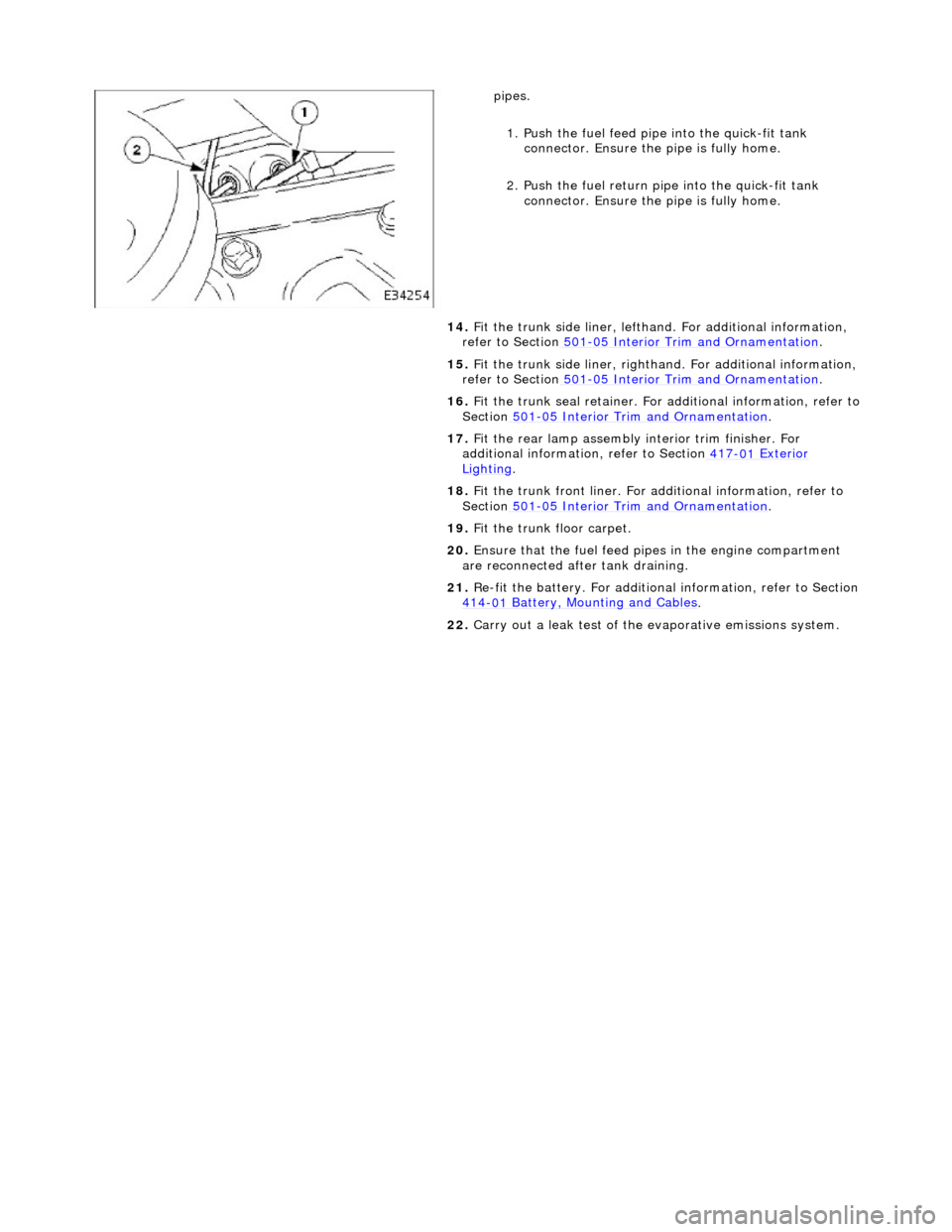
pipes.
1.
Push the fuel feed pipe into the quick-fit tank
connector. Ensu re the pipe is fully home.
2. Push the fuel return pi pe into the quick-fit tank
connector. Ensu re the pipe is fully home.
14. Fit the trunk side liner, lefthand. For additional information,
refer to Section 501
-0 5
Interior Trim and Ornamentation
.
15 . F
it the trunk side liner, righthan
d. For additional information,
refer to Section 501
-0 5
Interior Trim and Ornamentation
.
16 . F
it the trunk seal retainer. For a
dditional information, refer to
Section 501
-05
Interior Trim and Ornamentation
.
17 . F
it the rear lamp assembly
interior trim finisher. For
additional information, refer to Section 417
-01
Exterior
Ligh
ting.
18 . F
it the trunk front liner. For a
dditional information, refer to
Section 501
-05
Interior Trim and Ornamentation
.
19 . F
it the trunk floor carpet.
20. Ensure that the fuel feed pi pes in the engine compartment
are reconnected after tank draining.
21. Re-fit the battery. For additional information, refer to Section
414
-0 1
Battery, Mounting and Cables
.
22 . Carry ou
t a leak test of the evaporative emissions system.