Ground JAGUAR X308 1998 2.G Workshop Manual
[x] Cancel search | Manufacturer: JAGUAR, Model Year: 1998, Model line: X308, Model: JAGUAR X308 1998 2.GPages: 2490, PDF Size: 69.81 MB
Page 2302 of 2490

Installation
8. Remove lock link rod from door handle assembly.
1. Fit link rod to handle assembly.
2. Position handle assembly on door.
3. Position mounting bracket on insi de of door and connect lock
link rod.
4. Fit and tighten mounting bracket securing bolts.
5. Reposition PVC inner sheet in door.
6. Check for satisfactory door handle operation.
7. Connect ground cable to battery terminal. Refer to 86.15.15.
8. From driver door check for satisfactory operation of locking
system.
9. Disconnect ground cable from battery terminal. Refer to
86.15.15.
10. Ensure that water shedder contact area of door is clean and
dry.
11. Position water shedder at door and carefully pass harness
through.
12. Fit and firmly seat water shedder on door ensuring
satisfactory adhesion.
13. Fit door casing. Refer to 76.34.01.
14. Fit door casing veneer panel. Refer to 76.47.11.
15. Fit ground cable to battery term inal and fit cover to battery.
Refer to 86.15.15.
Page 2305 of 2490

1.
Position lock mechanism at door and connect operating cable.
2. Fit and fully seat cable rear abutment securing clip.
3. Fit and fully seat lock mechanism in door and fit and tighten
securing bolts.
4. Align glass guide and fit and tighten securing bolts.
5. Fit and fully seat inner cheater finisher.
6. Align and connect inner operating rod to lock mechanism.
7. Fit outer door handle operating rod to lock
8. Check for satisfactory door handle operation.
9. Reposition inner plastic sheet.
10. Connect lock actuator harness multiplug and fit to mounting
bracket.
11. Connect ground cable to battery terminal. Refer to 86.15.15.
12. From driver door, check for satisfactory operation of locking
system.
13. Disconnect ground cable from battery terminal. Refer to
86.15.19.
14. Ensure that water shedder contact area of door is clean and
dry.
15. Position water shedder at d oor and carefully pass door
harness through.
16. Fit and firmly seat water shedde r on door ensuring satifactory
adhesion.
17. Fit door casing. Refer to 76.34.04.
18. Fit door casing veneer panel. Refer to 76.47.12.
19. Connect ground cable to battery terminal and fit battery
cover. Refer to 86.15.15.
Page 2311 of 2490
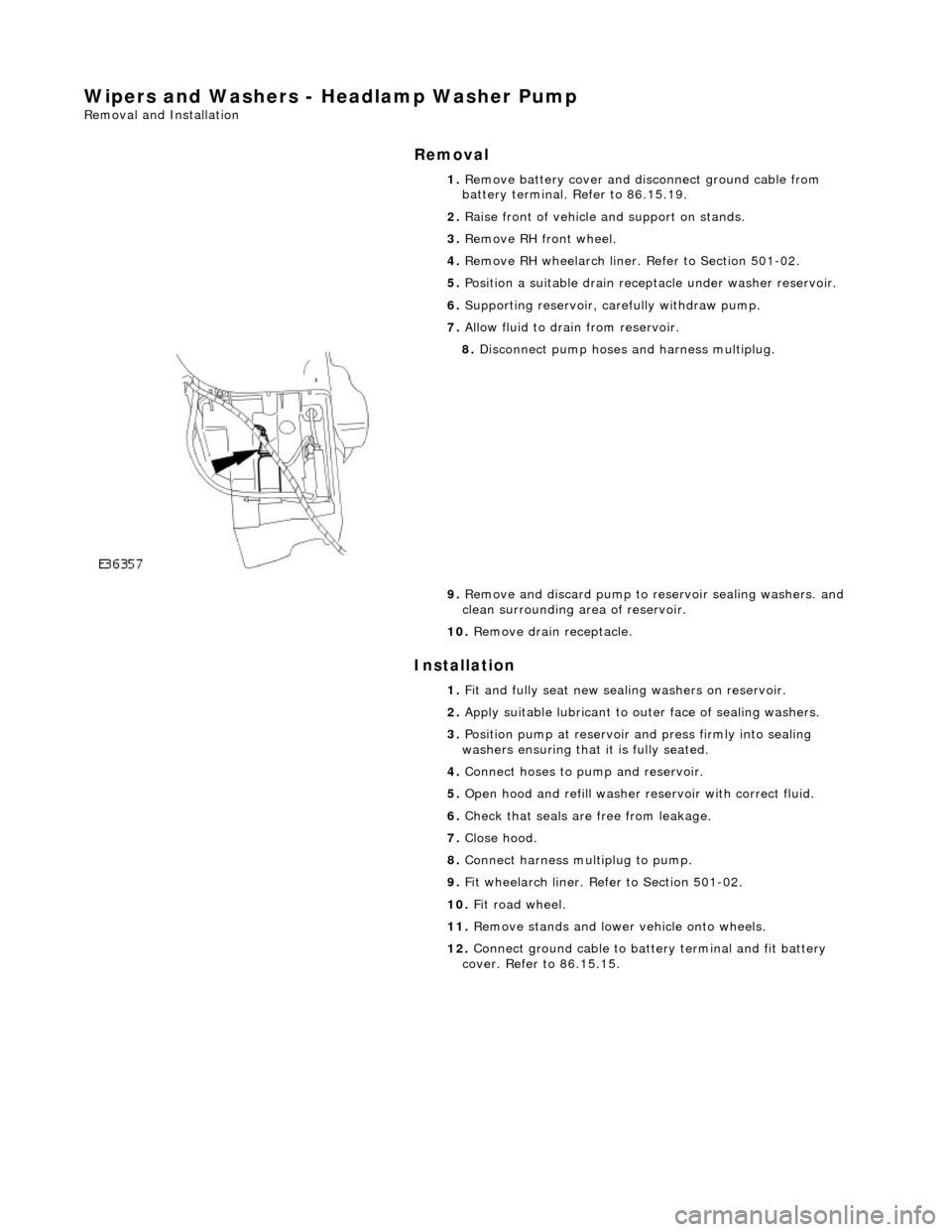
Wipers and Washers - Headlamp Washer Pump
Removal and Installation
Removal
Installation
1.
Remove battery cover and disc onnect ground cable from
battery terminal. Refer to 86.15.19.
2. Raise front of vehicle and support on stands.
3. Remove RH front wheel.
4. Remove RH wheelarch liner. Refer to Section 501-02.
5. Position a suitable drain recept acle under washer reservoir.
6. Supporting reservoir, ca refully withdraw pump.
7. Allow fluid to drain from reservoir.
8. Disconnect pump hoses and harness multiplug.
9. Remove and discard pump to re servoir sealing washers. and
clean surrounding area of reservoir.
10. Remove drain receptacle.
1. Fit and fully seat new sealing washers on reservoir.
2. Apply suitable lubricant to outer face of sealing washers.
3. Position pump at reservoir and press firmly into sealing
washers ensuring that it is fully seated.
4. Connect hoses to pump and reservoir.
5. Open hood and refill washer re servoir with correct fluid.
6. Check that seals are free from leakage.
7. Close hood.
8. Connect harness multiplug to pump.
9. Fit wheelarch liner. Refe r to Section 501-02.
10. Fit road wheel.
11. Remove stands and lowe r vehicle onto wheels.
12. Connect ground cable to batt ery terminal and fit battery
cover. Refer to 86.15.15.
Page 2312 of 2490
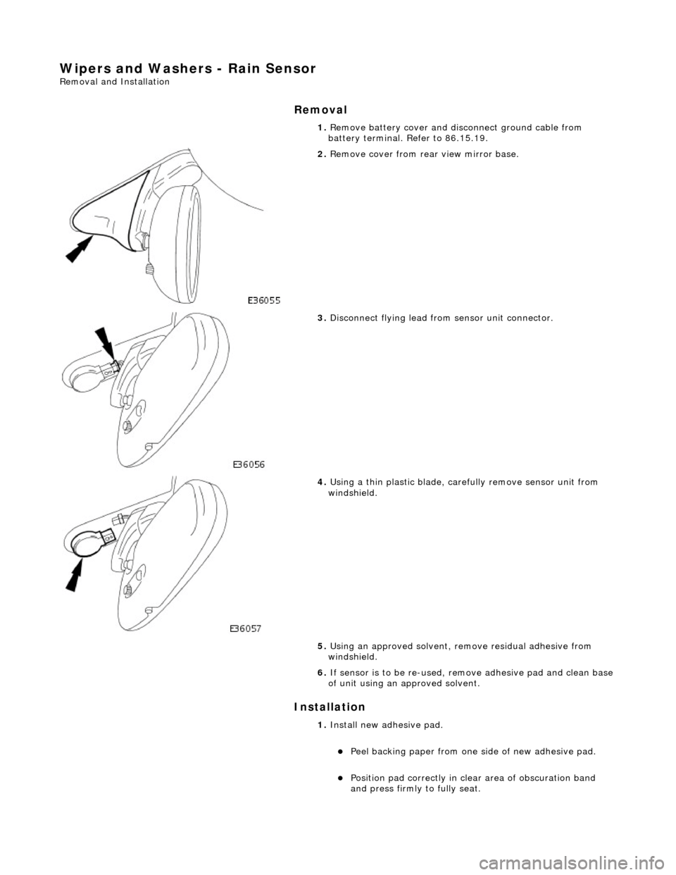
Wipers and Washers - Rain Sensor
Removal and Installation
Removal
Installation
1. Remove battery cover and disc onnect ground cable from
battery terminal. Refer to 86.15.19.
2. Remove cover from rear view mirror base.
3. Disconnect flying lead from sensor unit connector.
4. Using a thin plastic blade, carefully remove sensor unit from
windshield.
5. Using an approved solvent, re move residual adhesive from
windshield.
6. If sensor is to be re-used, remove adhesive pad and clean base
of unit using an approved solvent.
1. Install new ad hesive pad.
пЃ¬Peel backing paper from one si de of new adhesive pad.
пЃ¬Position pad correctly in clear area of obscuration band
and press firmly to fully seat.
Page 2313 of 2490

пЃ¬Peel remaining backing paper from adhesive pad.
2. Ensuring sensor is correctly orientated, press firmly into
position on adhesive pad.
3. Connect flying lead conn ector to sensor unit.
4. Install cover over sensor and mi rror base ensuring tangs fully
engage.
5. Connect ground cable to batter y terminal and install battery
cover. Refer to 86.15.15.
Page 2314 of 2490
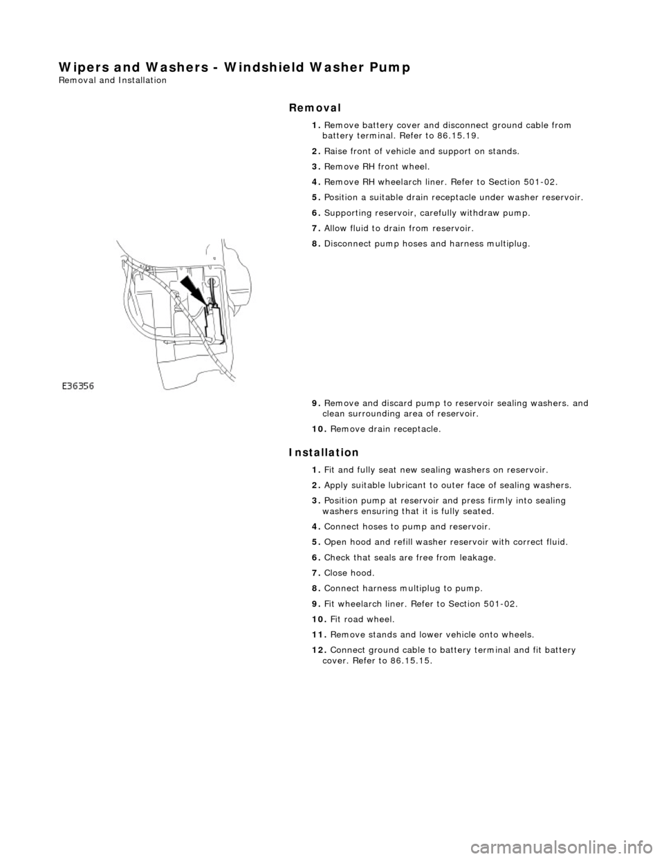
Wipers and Washers - Windshield Washer Pump
Removal and Installation
Removal
Installation
1.
Remove battery cover and disc onnect ground cable from
battery terminal. Refer to 86.15.19.
2. Raise front of vehicle and support on stands.
3. Remove RH front wheel.
4. Remove RH wheelarch liner. Refer to Section 501-02.
5. Position a suitable drain recept acle under washer reservoir.
6. Supporting reservoir, ca refully withdraw pump.
7. Allow fluid to drain from reservoir.
8. Disconnect pump hoses and harness multiplug.
9. Remove and discard pump to re servoir sealing washers. and
clean surrounding area of reservoir.
10. Remove drain receptacle.
1. Fit and fully seat new sealing washers on reservoir.
2. Apply suitable lubricant to outer face of sealing washers.
3. Position pump at reservoir and press firmly into sealing
washers ensuring that it is fully seated.
4. Connect hoses to pump and reservoir.
5. Open hood and refill washer re servoir with correct fluid.
6. Check that seals are free from leakage.
7. Close hood.
8. Connect harness multiplug to pump.
9. Fit wheelarch liner. Refe r to Section 501-02.
10. Fit road wheel.
11. Remove stands and lowe r vehicle onto wheels.
12. Connect ground cable to batt ery terminal and fit battery
cover. Refer to 86.15.15.
Page 2316 of 2490
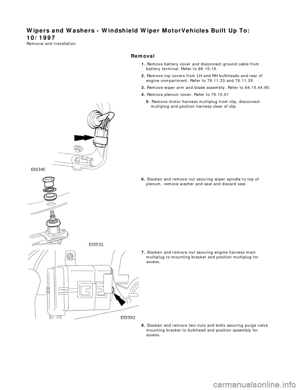
Wipers and Washers - Windshield Wiper MotorVehicles Built Up To:
10/1997
Removal and Installation
Removal
1. Remove battery cover and disc onnect ground cable from
battery terminal. Refer to 86.15.19.
2. Remove top covers from LH an d RH bulkheads and rear of
engine compartment. Refer to 76.11.33 and 76.11.35.
3. Remove wiper arm and blade as sembly. Refer to 84.15.44.90.
4. Remove plenum cover. Refer to 76.10.01
5. Remove motor harness multiplug from clip, disconnect
multiplug and position harness clear of clip.
6. Slacken and remove nut securi ng wiper spindle to top of
plenum, remove washer and seal and discard seal.
7. Slacken and remove nut securing engine harness main
multiplug to mounting bracke t and position multiplug for
access.
8. Slacken and remove two nuts an d bolts securing purge valve
mounting bracket to bulkhead and position assembly for
access.
Page 2318 of 2490

Installation
1.
Position motor in housing and fi t and tighten securing nuts and
bolts.
2. Apply suitable lubricant to bore of new spindle inner seal and
fit seal over motor spindle.
3. Holding the capillary and purge valve clear, position
motor/housing assembly on bulkhead.
4. Seat motor spindle seal correctly in upper plenum aperture and
ensure that housing lo cates on lower studs.
5. Fit and tighten the housin g upper securing bolts.
6. Fit and tighten the housing lower securing screws and slide
locking clips inwards.
7. Position throttle cable adjustment bracket on throttle body and
fit and tighten securing bolts.
8. Position purge valve bracket at bulkhead and fit and tighten
securing bolt and nuts.
9. Position engine harness multiplu g on mounting bracket and fit
and tighten securing nut.
10. Connect motor harness multiplug and locate in retaining clip.
11. Apply suitable lubricant to bore of new outer seal and fit with
washer to motor spindle.
12. Fit and fully tighten collar nut on motor spindle.
13. Fit plenum cover. Refer to 76.10.01.
14. Fit wiper arm and blade. Refer to 84.15.44.90.
15. Fit top covers to LH and RH bulkheads and rear of engine
compartment. refer to 76.11.33 and 76.11.35.
16. Fit ground cable to battery te rminal and cover to battery.
Refer to 86.15.15.
Page 2319 of 2490
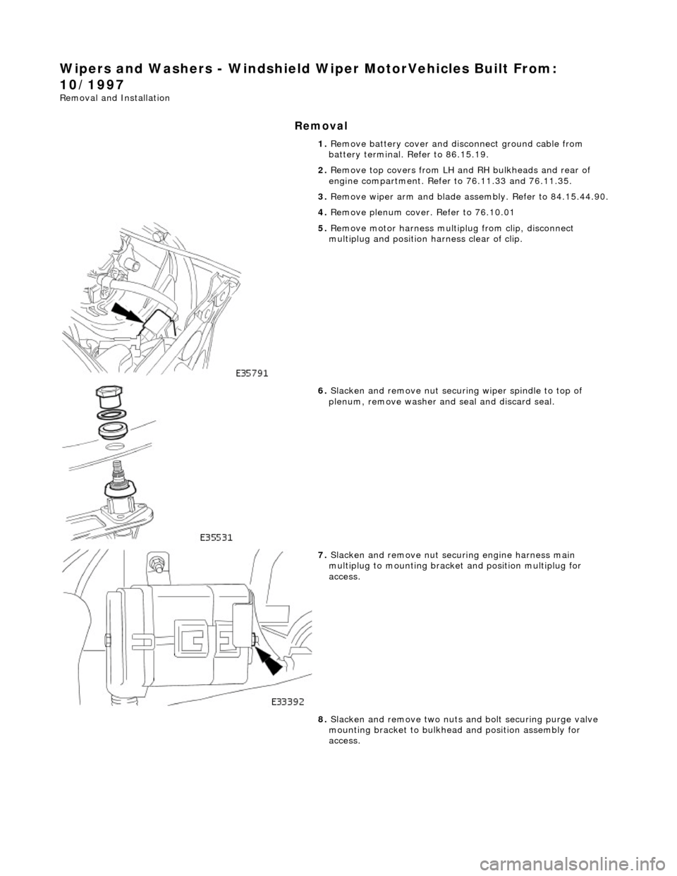
Wipers and Washers - Windshield Wiper MotorVehicles Built From:
10/1997
Removal and Installation
Removal
1. Remove battery cover and disc onnect ground cable from
battery terminal. Refer to 86.15.19.
2. Remove top covers from LH an d RH bulkheads and rear of
engine compartment. Refer to 76.11.33 and 76.11.35.
3. Remove wiper arm and blade as sembly. Refer to 84.15.44.90.
4. Remove plenum cover. Refer to 76.10.01
5. Remove motor harness multiplug from clip, disconnect
multiplug and position harness clear of clip.
6. Slacken and remove nut securi ng wiper spindle to top of
plenum, remove washer and seal and discard seal.
7. Slacken and remove nut securing engine harness main
multiplug to mounting bracke t and position multiplug for
access.
8. Slacken and remove two nuts an d bolt securing purge valve
mounting bracket to bulkhead and position assembly for
access.
Page 2321 of 2490

9.
Fit and fully tighten collar nut on motor spindle.
10. Fit plenum cover. Refer to 76.10.01.
11. Fit wiper arm and blade. Refer to 84.15.44.90.
12. Fit top covers to LH and RH bulkheads and rear of engine
compartment. refer to 76.11.33 and 76.11.35.
13. Fit ground cable to battery te rminal and cover to battery.
Refer to 86.15.15.