ECU JAGUAR X308 1998 2.G Workshop Manual
[x] Cancel search | Manufacturer: JAGUAR, Model Year: 1998, Model line: X308, Model: JAGUAR X308 1998 2.GPages: 2490, PDF Size: 69.81 MB
Page 1756 of 2490
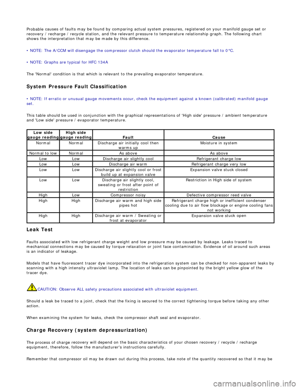
Probable
causes of faults may be found by comparing actual
system pressures, registered on your manifold gauge set or
recovery / recharge / recycle station, and the relevant pressure to temperature relationship graph. The following chart
shows the interpretation that ma y be made by this difference.
• NOTE: The A/CCM will disengage the compressor clutch should the evaporator temperature fall to 0°C.
• NOTE: Graphs are typical for HFC 134A
The 'Normal' condition is that which is relevant to the prevailing evaporator temperature.
System Pressure Fault Classification
• NOTE
: If erratic or unusual gauge move
ments occur, check the equipment against a known (calibrated) manifold gauge
set.
This table should be used in conjunction with the graphical representations of 'High side' pressure / ambient temperature
and 'Low side' pressure / evaporator temperature.
Leak
Test
F
a
ults associated with low re
frigerant charge weight and low pressure ma y be caused by leakage. Leaks traced to
mechanical connections may be caused by to rque relaxation or joint face contamination. Evidence of oil around such areas
is an indicator of leakage.
Models that have fluorescent tracer dye incorporated into the refrigeration system can be checke d for non-apparent leaks by
scanning with a high intensity ultraviolet lamp. The location of leaks can be pinpointed by the bright yellow glow of the
tracer dye.
CAUTION: Observe ALL safety precautions associated with ultraviolet equipment.
Should a leak be traced to a joint, check that the fixing is secured to the correct tightening torque before taking any other
action.
When examining the system for leaks, chec k the compressor shaft seal and evaporator.
Charge Re
covery (system depressurization)
The process of
charge r
ecovery will depe
nd on the basic characteristics of your chosen recovery / recycle / recharge
equipment, therefore, follow the manu facturer's instructions carefully.
Remember that compressor oil may be drawn out during this process, take note of the quantity recovered so that it may be
Lo
w side
gauge reading
High s i
de
gauge reading
Fau l
t
Cause
No
r
mal
No
r
mal
Di
sc
harge air initially cool then
warms up
Mois
ture in system
N
ormal
to low
No
r
mal
As aboveAs above
LowLowD
i
scharge air slightly cool
Ref
r
igerant charge low
LowLowDi
scharge air warm
Refr
igerant charge very low
LowLowDi
scharge air slightly cool or frost
build up at expansion valve
Expansion valve st
uck closed
LowLowDi
scharge air slightly cool,
sweating or frost after point of restriction
Restri
ction in High side of system
HighLowCompressor noisyDe
fe
ctive compressor reed valve
HighHighD
i
scharge air warm and high side
pipes hot
Refri
gerant charge high or inefficient condenser
cooling due to air flow blockage or engine cooling fans
not working
HighHighD i
scharge air warm / Sweating or
frost at evaporator
Expans ion valve st
uck open
Page 1777 of 2490
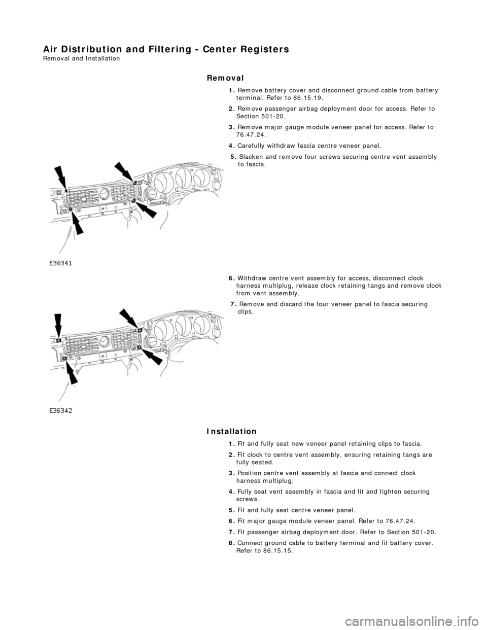
Air Distribution and Filtering - Center Registers
Removal and Installation
Removal
Installation
1.
Remove battery cover and disconnect ground cable from battery
terminal. Refer to 86.15.19.
2. Remove passenger airbag deployment door for access. Refer to
Section 501-20.
3. Remove major gauge module veneer panel for access. Refer to
76.47.24.
4. Carefully withdraw fascia centre veneer panel.
5. Slacken and remove four screws securing centre vent assembly
to fascia.
6. Withdraw centre vent assembly for access, disconnect clock
harness multiplug, release clock retaining tangs and remove clock
from vent assembly.
7. Remove and discard the four veneer panel to fascia securing
clips.
1. Fit and fully seat new veneer panel retaining clips to fascia.
2. Fit clock to centre vent assemb ly, ensuring retaining tangs are
fully seated.
3. Position centre vent assembly at fascia and connect clock
harness multiplug.
4. Fully seat vent assembly in fascia and fit and tighten securing
screws.
5. Fit and fully seat centre veneer panel.
6. Fit major gauge module veneer panel. Refer to 76.47.24.
7. Fit passenger airbag deployment door. Refer to Section 501-20.
8. Connect ground cable to battery terminal and fit battery cover.
Refer to 86.15.15.
Page 1780 of 2490
Air Distribution and Filtering - Passenger Side Blower Motor
Removal and Installation
Removal
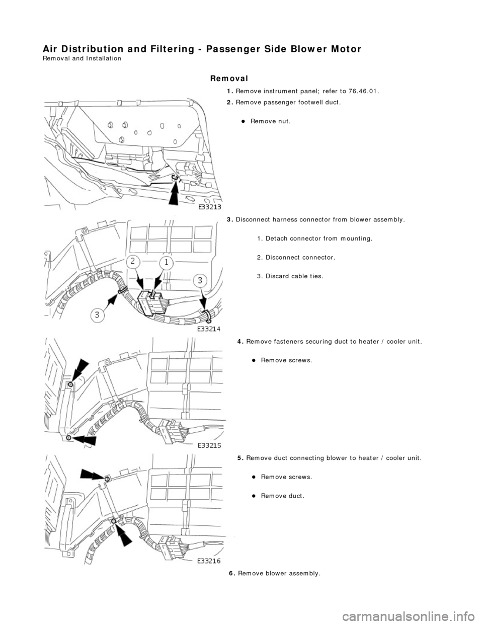
1. Remove instrument panel; refer to 76.46.01.
2. Remove passenger footwell duct.
Remove nut.
3. Disconnect harness connector from blower assembly.
1. Detach connector from mounting.
2. Disconnect connector.
3. Discard cable ties.
4. Remove fasteners securing duct to heater / cooler unit.
Remove screws.
5. Remove duct connecting blower to heater / cooler unit.
Remove screws.
Remove duct.
6. Remove blower assembly.
Page 1784 of 2490
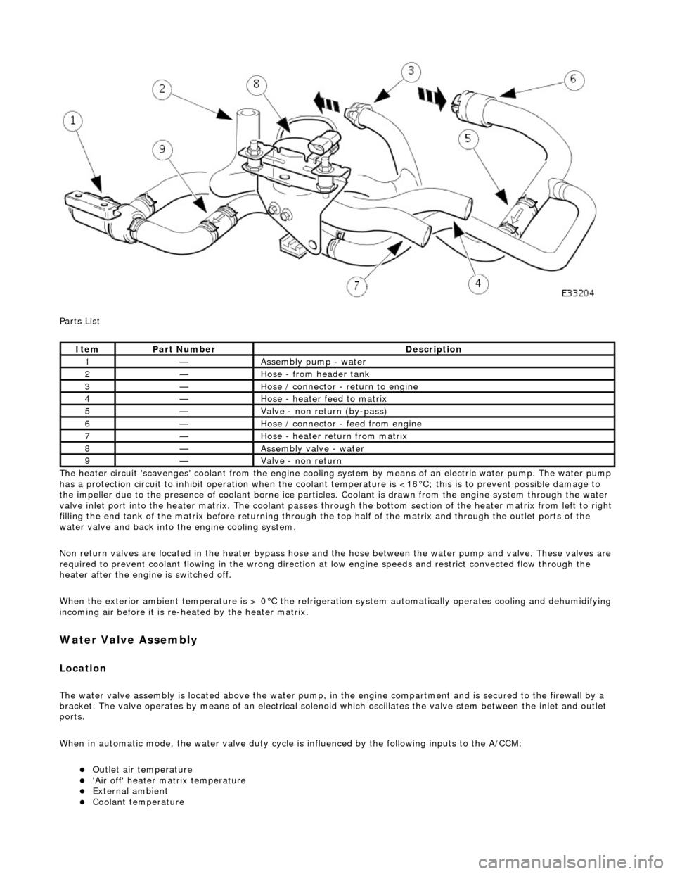
Parts List
The heater circuit 'scavenges' coolant from the engine cooling system by mean s of an electric water pump. The water pump
has a protection circuit to inhibit operation when the coolant temperature is <16°C; this is to prevent possible damage to
the impeller due to the presence of coolant borne ice particles. Coolant is drawn from the en gine system through the water
valve inlet port into the heater matrix. The coolant passes thro ugh the bottom section of the heater matrix from left to right
filling the end tank of the matrix before returning through the top half of the ma trix and through the outlet ports of the
water valve and back into the engine cooling system.
Non return valves are located in the heat er bypass hose and the hose between the water pump and valve. These valves are
required to prevent coolant flowing in th e wrong direction at low engine speeds and restrict convected flow through the
heater after the engine is switched off.
When the exterior ambient temperature is > 0°C the refrigerat ion system automatically operates cooling and dehumidifying
incoming air before it is re -heated by the heater matrix.
Water Valve Assembly
Location
The water valve assembly is located above the water pump, in the engine compartmen t and is secured to the firewall by a
bracket. The valve operates by means of an electrical solenoid which oscillates the valve stem between the inlet and outlet
ports.
When in automatic mode, the water valve duty cycle is influenced by the following inputs to the A/CCM:
Outlet air temperature 'Air off' heater matrix temperature External ambient Coolant temperature
ItemPart NumberDescription
1—Assembly pump - water
2—Hose - from header tank
3—Hose / connector - return to engine
4—Hose - heater feed to matrix
5—Valve - non return (by-pass)
6—Hose / connector - feed from engine
7—Hose - heater return from matrix
8—Assembly valve - water
9—Valve - non return
Page 1789 of 2490
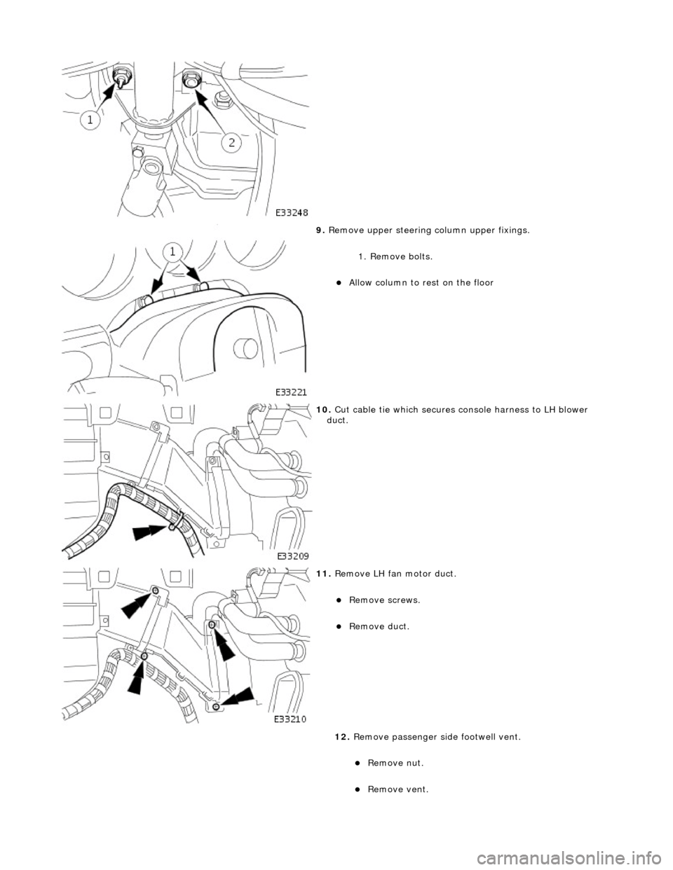
9. Remove upper steering column upper fixings.
1. Remove bolts.
Allow column to rest on the floor
10. Cut cable tie which secures console harness to LH blower
duct.
11. Remove LH fan motor duct.
Remove screws.
Remove duct.
12. Remove passenger si de footwell vent.
Remove nut.
Remove vent.
Page 1790 of 2490
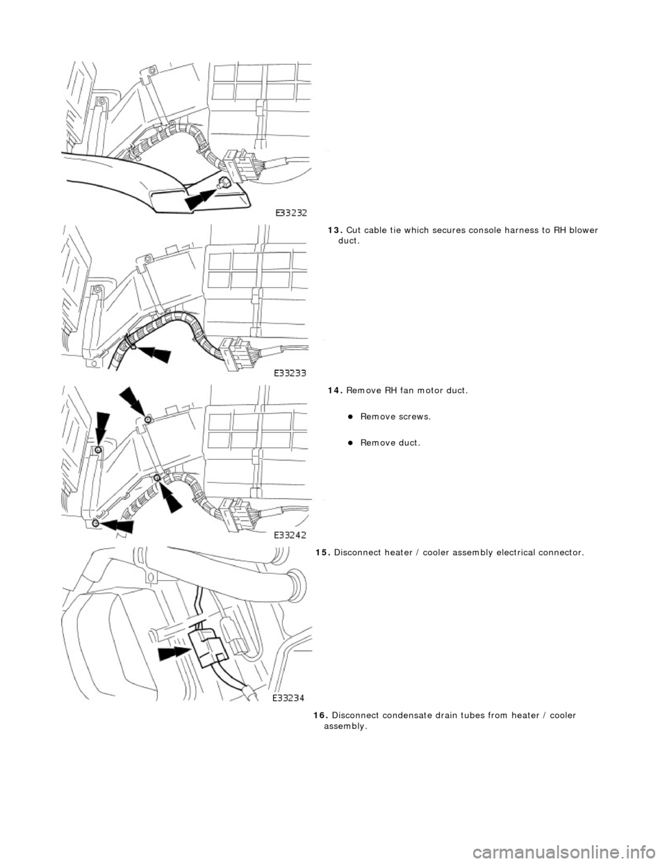
13. Cut cable tie which secures console harness to RH blower
duct.
14. Remove RH fan motor duct.
Remove screws.
Remove duct.
15. Disconnect heater / cooler assembly electrical connector.
16. Disconnect condensate drain tubes from heater / cooler
assembly.
Page 1791 of 2490
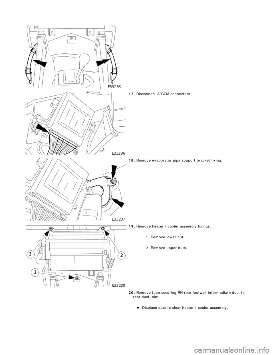
17. Disconnect A/CCM connectors.
18. Remove evaporator pipe support bracket fixing.
19. Remove heater / cooler assembly fixings.
1. Remove lower nut.
2. Remove upper nuts.
20. Remove tape securing RH rear footwell intermediate duct to
rear duct joint.
Displace duct to clear heater / cooler assembly.
Page 1792 of 2490
Installation
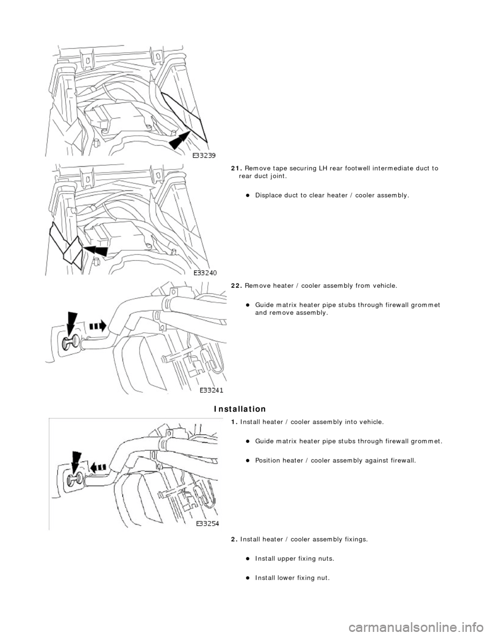
21. Remove tape securing LH rear footwell intermediate duct to
rear duct joint.
Displace duct to clear heater / cooler assembly.
22. Remove heater / cooler assembly from vehicle.
Guide matrix heater pipe stubs through firewall grommet
and remove assembly.
1. Install heater / cooler assembly into vehicle.
Guide matrix heater pipe stubs through firewall grommet.
Position heater / cooler as sembly against firewall.
2. Install heater / cooler assembly fixings.
Install upper fixing nuts.
Install lower fixing nut.
Page 1793 of 2490
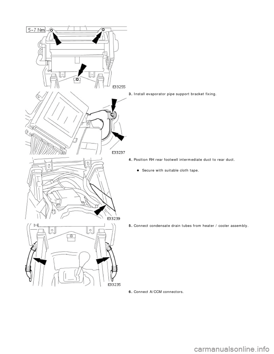
3. Install evaporator pipe support bracket fixing.
4. Position RH rear footwell inte rmediate duct to rear duct.
Secure with suitable cloth tape.
5. Connect condensate drain tubes from heater / cooler assembly.
6. Connect A/CCM connectors.
Page 1794 of 2490

7. Position LH rear footwell inte rmediate duct to rear duct.
Secure with suitable cloth tape.
8. Connect heater / cooler assembly electrical connector.
9. Install LH fan motor duct.
Install duct.
Install screws.
10. Install cable tie to secure console harness to LH blower duct.