ECU JAGUAR X308 1998 2.G Workshop Manual
[x] Cancel search | Manufacturer: JAGUAR, Model Year: 1998, Model line: X308, Model: JAGUAR X308 1998 2.GPages: 2490, PDF Size: 69.81 MB
Page 1893 of 2490
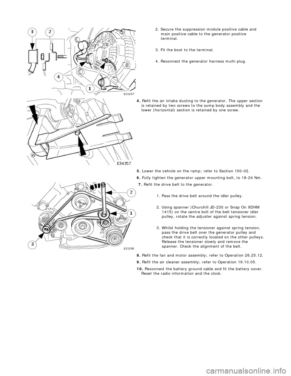
2. Secure the suppression module positive cable and
main positive cable to the generator positive
terminal.
3. Fit the boot to the terminal.
4. Reconnect the generator harness multi-plug.
4. Refit the air intake ducting to the generator. The upper section
is retained by two screws to the sump body assembly and the
lower (horizontal) section is retained by one screw.
5. Lower the vehicle on the ramp ; refer to Section 100-02.
6. Fully tighten the generator upper mounting bolt, to 18-24 Nm.
7. Refit the drive belt to the generator.
1. Pass the drive belt around the idler pulley.
2. Using spanner )Churchill JD-230 or Snap On XDHM 1415) on the centre bolt of the belt tensioner idler
pulley, rotate the adjuster against spring tension.
3. Whilst holding the tensioner against spring tension, pass the drive belt over the generator pulley and
check that it is correctly located on the other pulleys.
Release the tensioner slowly and remove the
spanner. Check the alignment of the belt.
8. Refit the fan and motor assembly ; refer to Operation 26.25.12.
9. Refit the air cleaner assembly; refer to Operation 19.10.05.
10. Reconnect the battery ground cable and fit the battery cover.
Reset the radio inform ation and the clock.
Page 1895 of 2490
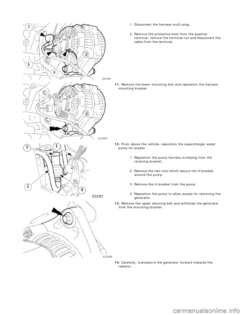
1. Disconnect the harness multi-plug.
2. Remove the protective boot from the positive
terminal, remove the termin al nut and disconnect the
cable from the terminal.
11. Remove the lower mounting bolt and reposition the harness
mounting bracket.
12. From above the vehicle, reposi tion the supercharger water
pump for access.
1. Reposition the pump harness multiplug from the
retaining bracket.
2. Remove the two nuts which secure the U-bracket around the pump.
3. Remove the U-bracket from the pump.
4. Reposition the pump to al low access for removing the
generator.
13. Remove the upper securing bolt and withdraw the generator
from the mounting bracket.
14. Carefully, manoeuvre the ge nerator forward towards the
radiator.
Page 1897 of 2490
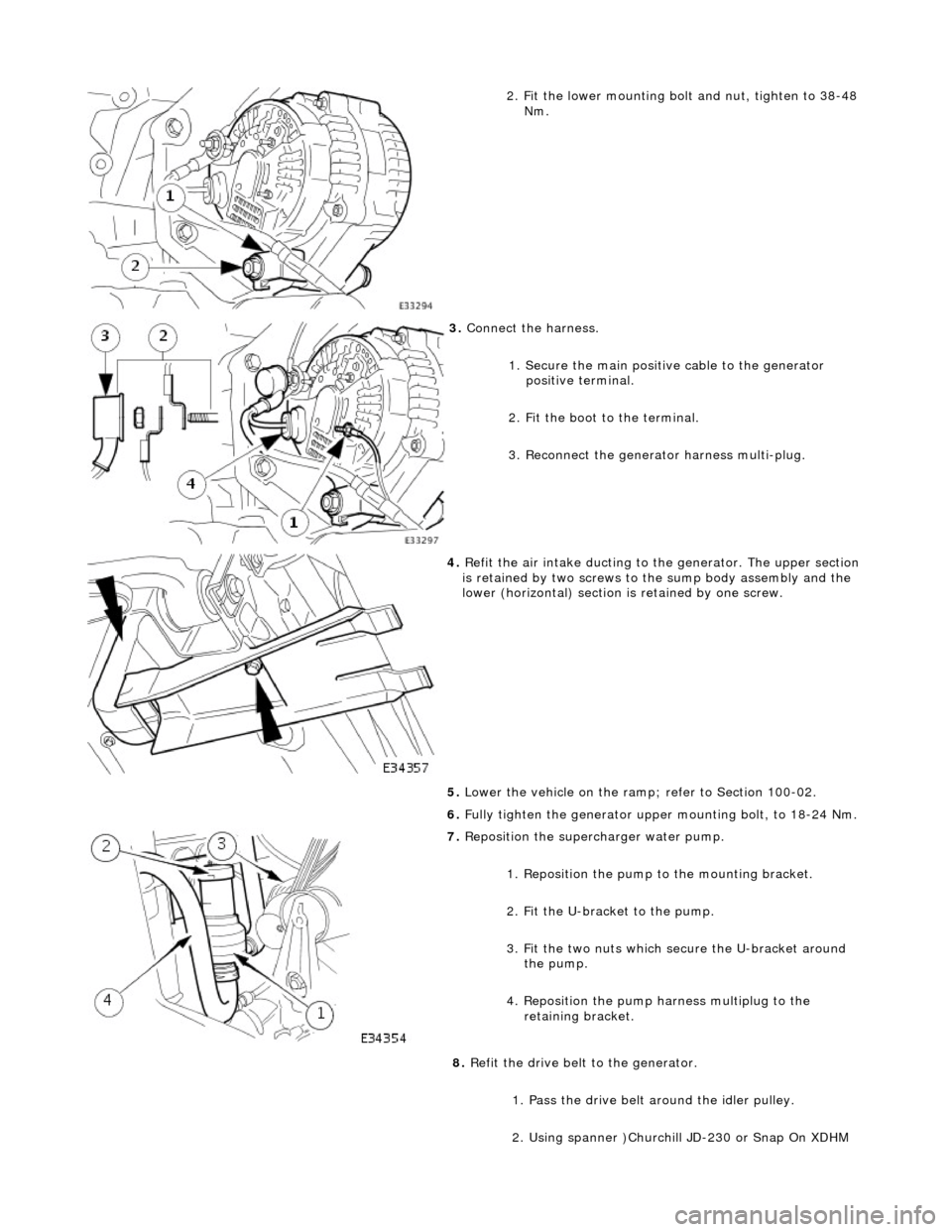
2. Fit the lower mounting bolt and nut, tighten to 38-48
Nm.
3. Connect the harness.
1. Secure the main positive cable to the generator positive terminal.
2. Fit the boot to the terminal.
3. Reconnect the generator harness multi-plug.
4. Refit the air intake ducting to the generator. The upper section
is retained by two screws to the sump body assembly and the
lower (horizontal) section is retained by one screw.
5. Lower the vehicle on the ramp ; refer to Section 100-02.
6. Fully tighten the generator upper mounting bolt, to 18-24 Nm.
7. Reposition the superc harger water pump.
1. Reposition the pump to the mounting bracket.
2. Fit the U-bracket to the pump.
3. Fit the two nuts which secure the U-bracket around the pump.
4. Reposition the pump harness multiplug to the retaining bracket.
8. Refit the drive belt to the generator.
1. Pass the drive belt around the idler pulley.
2. Using spanner )Churchill JD-230 or Snap On XDHM
Page 1899 of 2490

Generator and Regulator - Voltage Regulator
Removal and Installation
Removal
1. Disconnect the batt ery ground cable.
Remove the battery cover.
2. Remove the generator from the vehicle. Refer to Operation
86.10.02.
3. Remove the nut from the main terminal and remove the
insulator.
4. Remove the ground tag.
1. Remove the nut which secures the ground tag.
2. Remove the screw which secures the ground tag and remove the tag.
5. Remove the two remaining nuts which secure th e rear cover
and remove the cover.
Page 1900 of 2490
Installation
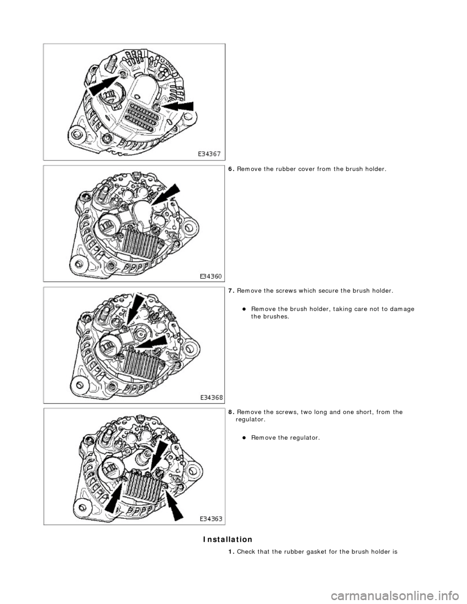
6. Remove the rubber cover from the brush holder.
7. Remove the screws which secure the brush holder.
Remove the brush holder, taking care not to damage
the brushes.
8. Remove the screws, two long and one short, from the
regulator.
Remove the regulator.
1. Check that the rubber gasket for the brush holder is
Page 1901 of 2490
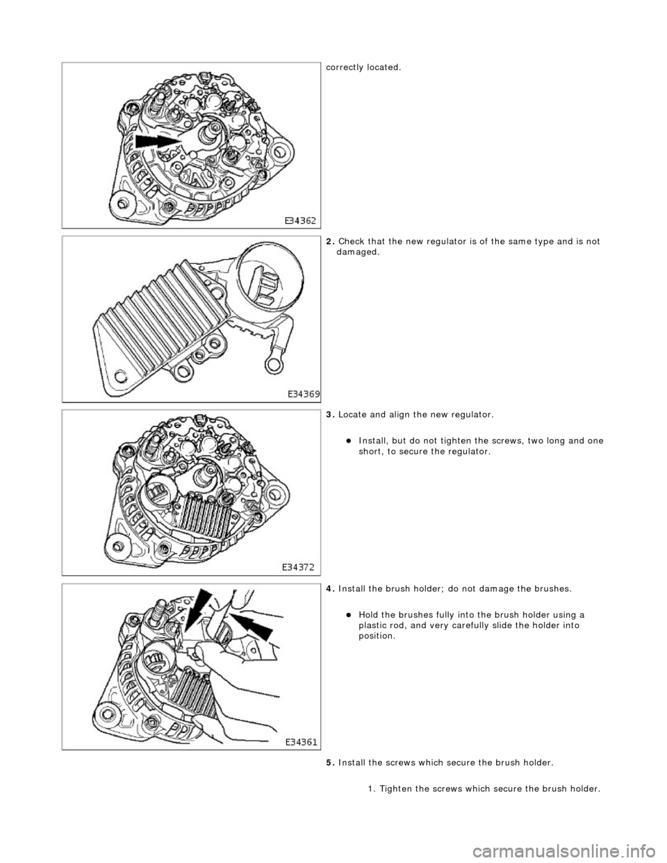
correctly located.
2. Check that the new regulator is of the same type and is not
damaged.
3. Locate and align the new regulator.
Install, but do not tighten the screws, two long and one
short, to secure the regulator.
4. Install the brush holder; do not damage the brushes.
Hold the brushes fully into the brush holder using a
plastic rod, and very carefully slide the holder into
position.
5. Install the screws which secure the brush holder.
1. Tighten the screws whic h secure the brush holder.
Page 1902 of 2490
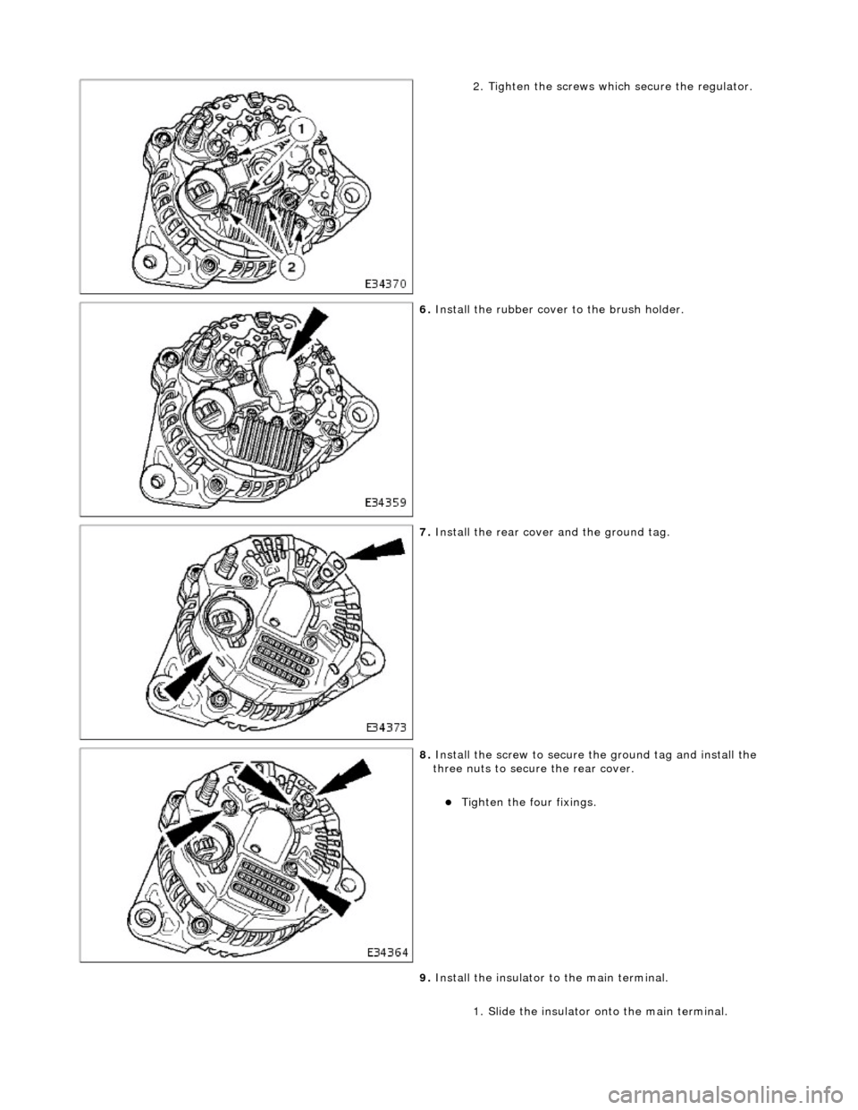
2. Tighten the screws which secure the regulator.
6. Install the rubber cover to the brush holder.
7. Install the rear cover and the ground tag.
8. Install the screw to secure th e ground tag and install the
three nuts to secure the rear cover.
Tighten the four fixings.
9. Install the insulator to the main terminal.
1. Slide the insulator on to the main terminal.
Page 1907 of 2490
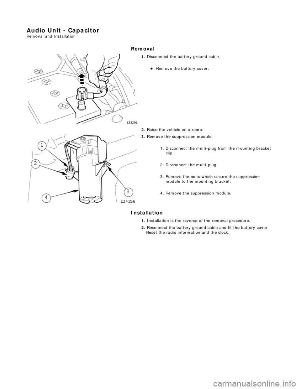
Audio Unit - Capacitor
Removal and Installation
Removal
Installation
1. Disconnect the batt ery ground cable.
Remove the battery cover.
2. Raise the vehicle on a ramp.
3. Remove the suppr ession module.
1. Disconnect the multi-plug from the mounting bracket clip.
2. Disconnect the multi-plug.
3. Remove the bolts which secure the suppression module to the mounting bracket.
4. Remove the su ppression module.
1. Installation is th e reverse of the re moval procedure.
2. Reconnect the battery ground cable and fit the battery cover.
Reset the radio inform ation and the clock.
Page 1920 of 2490
Direction indicator and side marker lamps
Each front direction indicator and side marker lamp is retained in the bumper cover by a lug at one end and a spring clip at
the other end. The side marker lamps are not electrically connected for certain markets.
The side repeater lamps are secured by sp ring clips on the lower edge of the lamp unit. In certain markets Jaguar leaper
badges are substituted for side repeater lamps.
Fog lamps
The fog lamps are located in recesses in the front bump er and secured by three screws. The la mps which are not
interchangeable left to right, are accessed from the rear of the bumper.
Operation
All lamps are controlled by the BPM which provides an appropriate output in response to an input received when a selected
switch is operated.
All lamps receive an input direct from th e BPM with the exception of the main be am, dip beam and front fog lamps which
receive an input from the BPM vi a the respective relays and fuses; refer to section 418-01.
Fault analysis must be undertaken using the PDU. Refer to Diagnosis and Testing.
Consult the relevant Electrical Guid e for details of circuit operation.
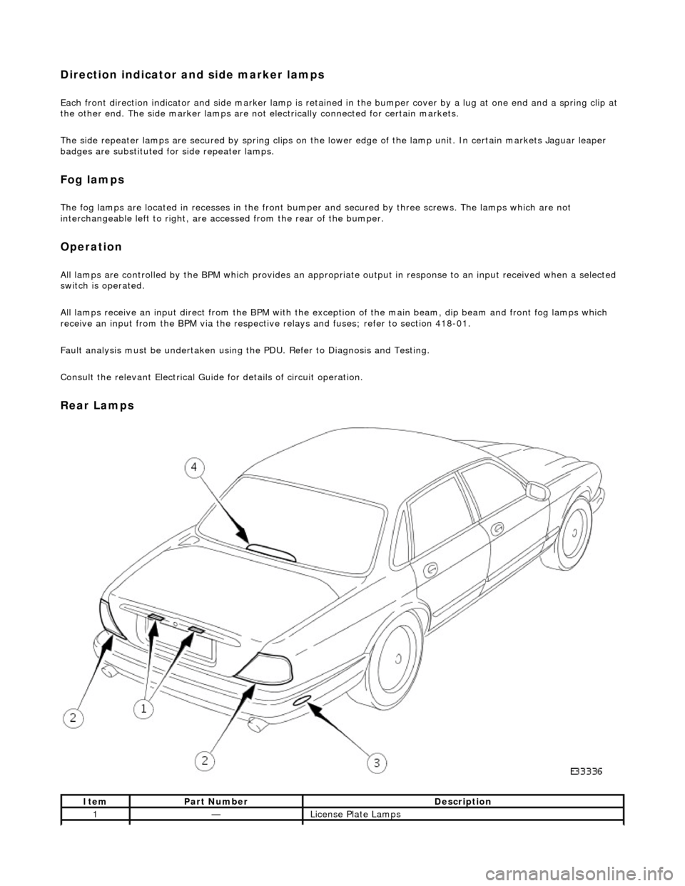
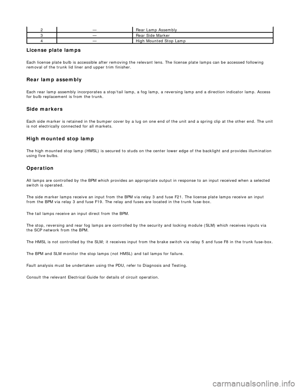
Rear Lamps
ItemPart NumberDescription
1—License Plate Lamps
Page 1921 of 2490
License plate lamps
Each license plate bulb is accessible after removing the relevant lens. The license plate lamps can be accessed following
removal of the trunk lid liner and upper trim finisher.
Rear lamp assembly
Each rear lamp assembly incorporates a stop/tail lamp, a fog lamp, a reversing lamp and a direction indicator lamp. Access
for bulb replacement is from the trunk.
Side markers
Each side marker is retained in the bumper cover by a lug on one end of the unit and a spring clip at the other end. The unit is not electrically connected for all markets.
High mounted stop lamp
The high mounted stop lamp (HMSL) is secu red to studs on the center lower edge of the backlight and provides illumination
using five bulbs.
Operation
All lamps are controlled by the BPM which pr ovides an appropriate output in response to an input received when a selected
switch is operated.
The side marker lamps receive an input from the BPM via relay 3 and fuse F21. The license plate lamps receive an input
from the BPM via relay 3 and fuse F19. The rela y and fuses are located in the trunk fuse-box.
The tail lamps receive an input direct from the BPM.
The stop, reversing and rear fog lamps are controlled by the security and locking module (SLM) which receives inputs via
the SCP network from the BPM.
The HMSL is not controlled by the SLM; it receives input from the brake switch via relay 5 and fuse F8 in the trunk fuse-box.
The BPM and SLM monitor the stop lamps (n ot HMSL) and tail lamps for failure.
Fault analysis must be undertaken using the PDU, refer to Diagnosis and Testing.
Consult the relevant Electrical Guid e for details of circuit operation.
2—Rear Lamp Assembly
3—Rear Side Marker
4—High Mounted Stop Lamp