fault code JAGUAR X308 1998 2.G Manual Online
[x] Cancel search | Manufacturer: JAGUAR, Model Year: 1998, Model line: X308, Model: JAGUAR X308 1998 2.GPages: 2490, PDF Size: 69.81 MB
Page 1627 of 2490
GO to H8
No
Renew O2 sensor. Reconnect plug(s)
GO to H7
H7
: STOP
Perform
appropriate service drive cycle and check for the
presence of DTC.
1
Has
the fault code cleared?
Yes STOP
No Contact Jaguar Service
H
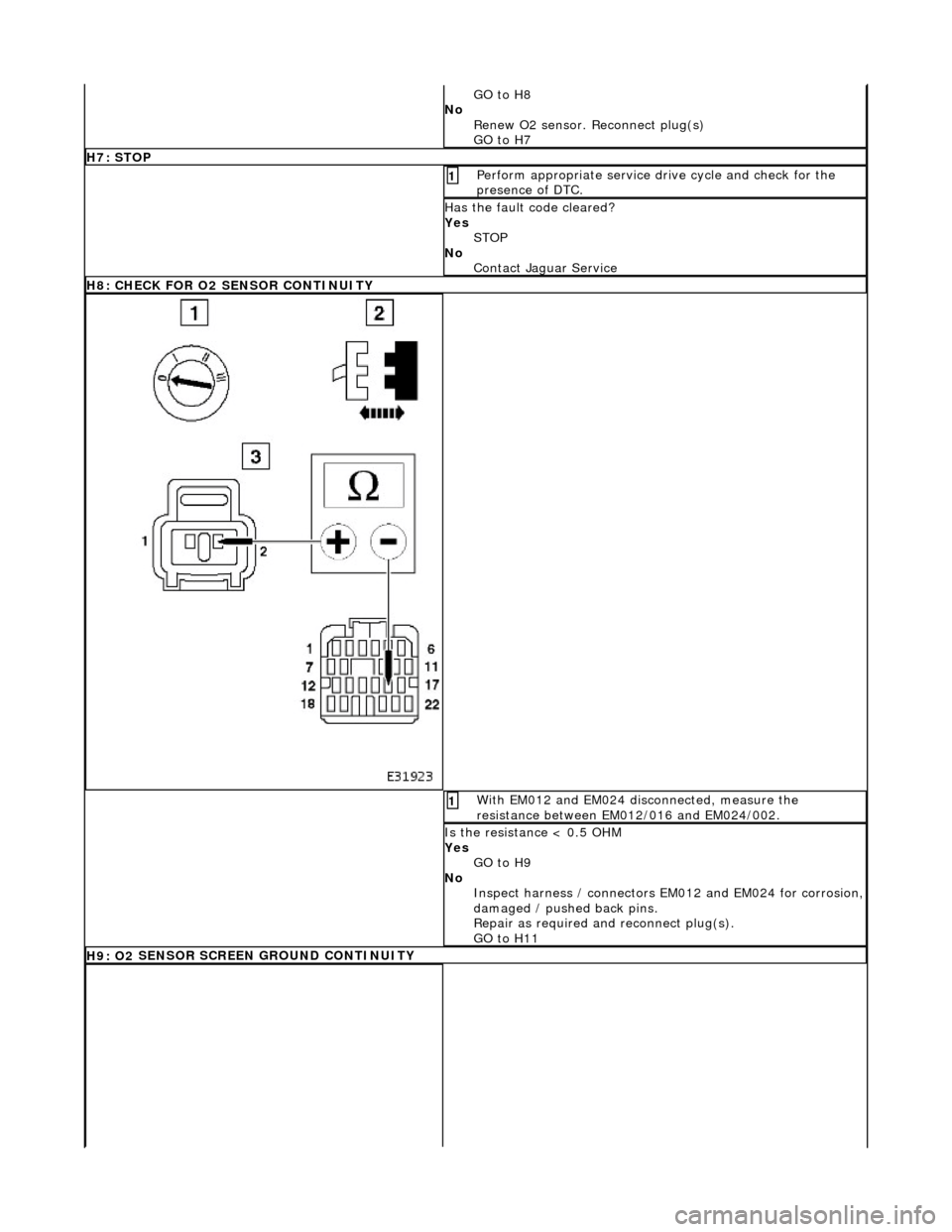
8: CHECK FOR O2 SENSOR CONTINUITY
W
ith EM012 and EM024 disconnected, measure the
resistance between EM012/016 and EM024/002.
1
I
s the resistance < 0.5 OHM
Yes GO to H9
No Inspect harness / connectors EM012 and EM024 for corrosion,
damaged / pushed back pins.
Repair as required an d reconnect plug(s).
GO to H11
H9: O2
SENSOR SCREEN GROUND CONTINUITY
Page 1629 of 2490
W
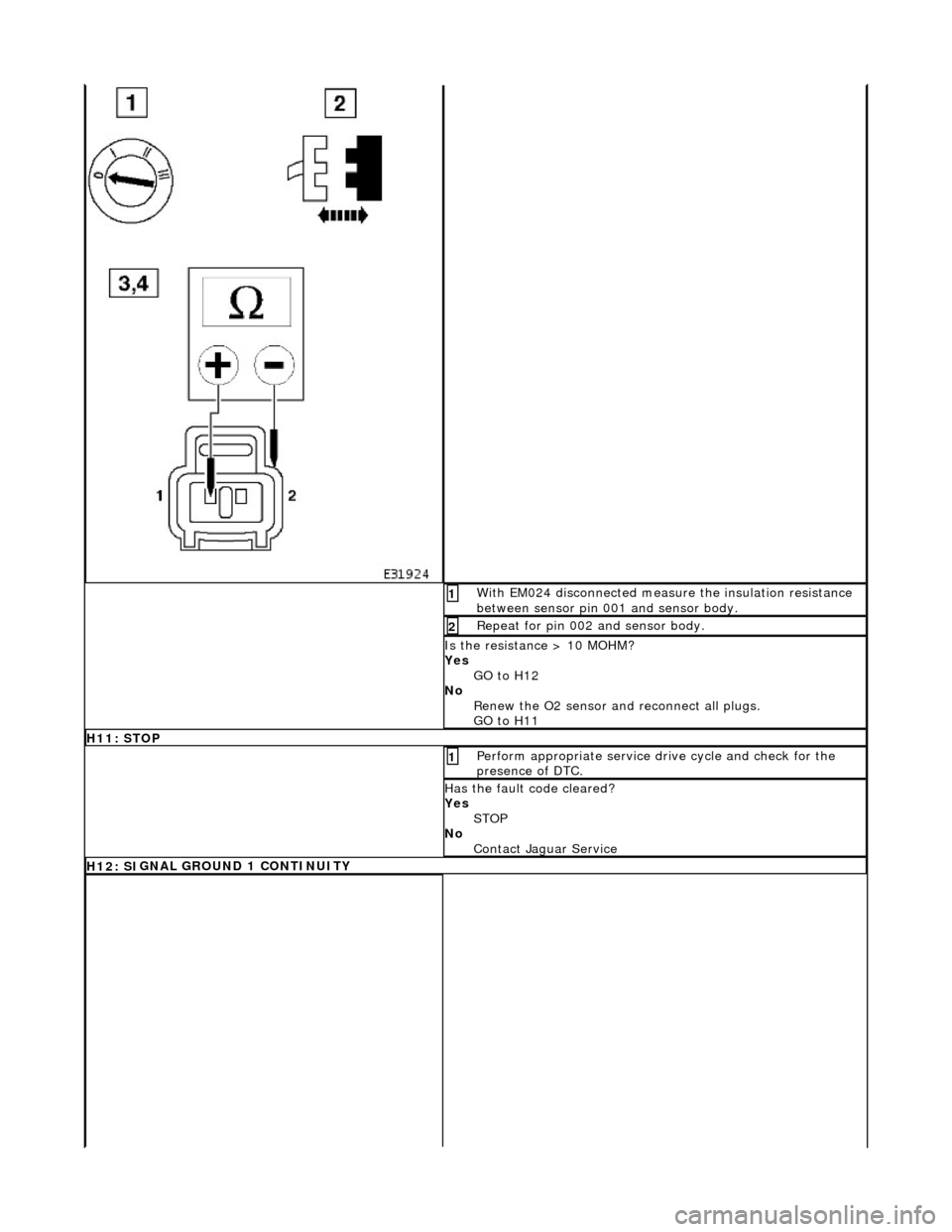
ith EM024 disconnected measur
e the insulation resistance
between sensor pin 001 and sensor body.
1
Repeat
for pin 002 and sensor body.
2
I
s the resistance > 10 MOHM?
Yes GO to H12
No Renew the O2 sensor and reconnect all plugs.
GO to H11
H1
1: STOP
Perform
appropriate service drive cycle and check for the
presence of DTC.
1
Has
the fault code cleared?
Yes STOP
No Contact Jaguar Service
H12: SI
GNAL GROUND 1 CONTINUITY
Page 1631 of 2490
W
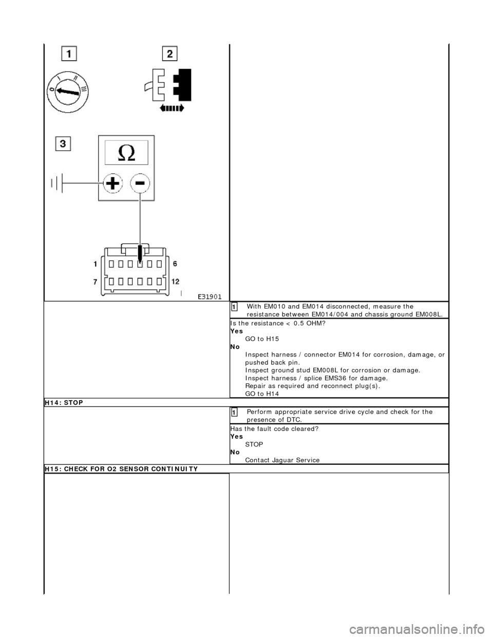
ith EM010 and EM014 disconnected, measure the
resistance between EM014/004 and chassis ground EM008L.
1
I
s the resistance < 0.5 OHM?
Yes GO to H15
No Inspect harness / connector EM014 for corrosion, damage, or
pushed back pin.
Inspect ground stud EM008L for corrosion or damage.
Inspect harness / spli ce EMS36 for damage.
Repair as required an d reconnect plug(s).
GO to H14
H1
4: STOP
Perform
appropriate service drive cycle and check for the
presence of DTC.
1
Has
the fault code cleared?
Yes STOP
No Contact Jaguar Service
H
15: CHECK FOR O2 SENSOR CONTINUITY
Page 1637 of 2490
M
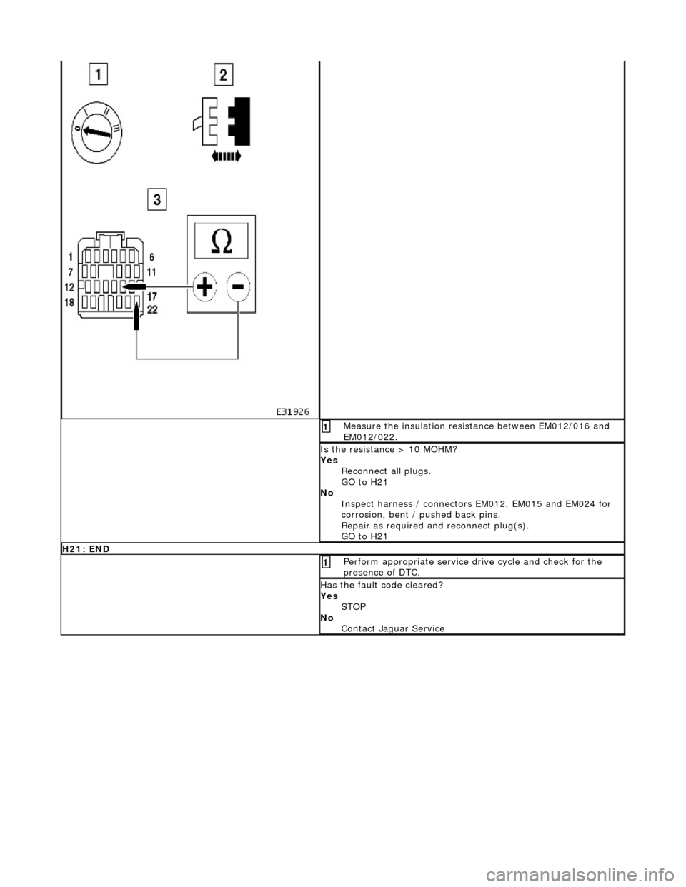
easure the insulation resistance between EM012/016 and
EM012/022.
1
I
s the resistance > 10 MOHM?
Yes Reconnect all plugs.
GO to H21
No Inspect harness / connectors EM012, EM015 and EM024 for
corrosion, bent / pushed back pins.
Repair as required an d reconnect plug(s).
GO to H21
H2
1: END
Perform
appropriate service drive cycle and check for the
presence of DTC.
1
Has
the fault code cleared?
Yes STOP
No Contact Jaguar Service
Page 1712 of 2490
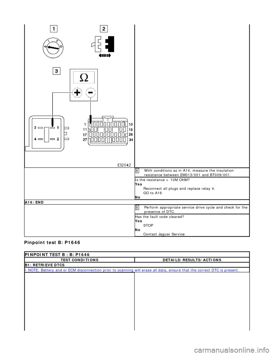
Pinpoint test B:
P1646
W
i
th conditions as in A14, measure the insulation
resistance between EM013/001 and BT009/001.
1
I s
the resistance > 10M OHM?
Yes Reconnect all plugs and replace relay 4.
GO to A16
No
A 16:
END
Perform
a
ppropriate service drive cycle and check for the
presence of DTC.
1
Has th
e fault code cleared?
Yes STOP
No Contact Ja
guar Serv ice
PINPOINT TEST B : B: P1646
TE
ST CONDITIONS
D
E
TAILS/RESULTS/ACTIONS
B1
: RETRI
EVE DTCS
•
NOTE
: Battery and or ECM disconnection prior to scanning wi
ll erase all data, ensure that the correct DTC is present.
Page 1726 of 2490
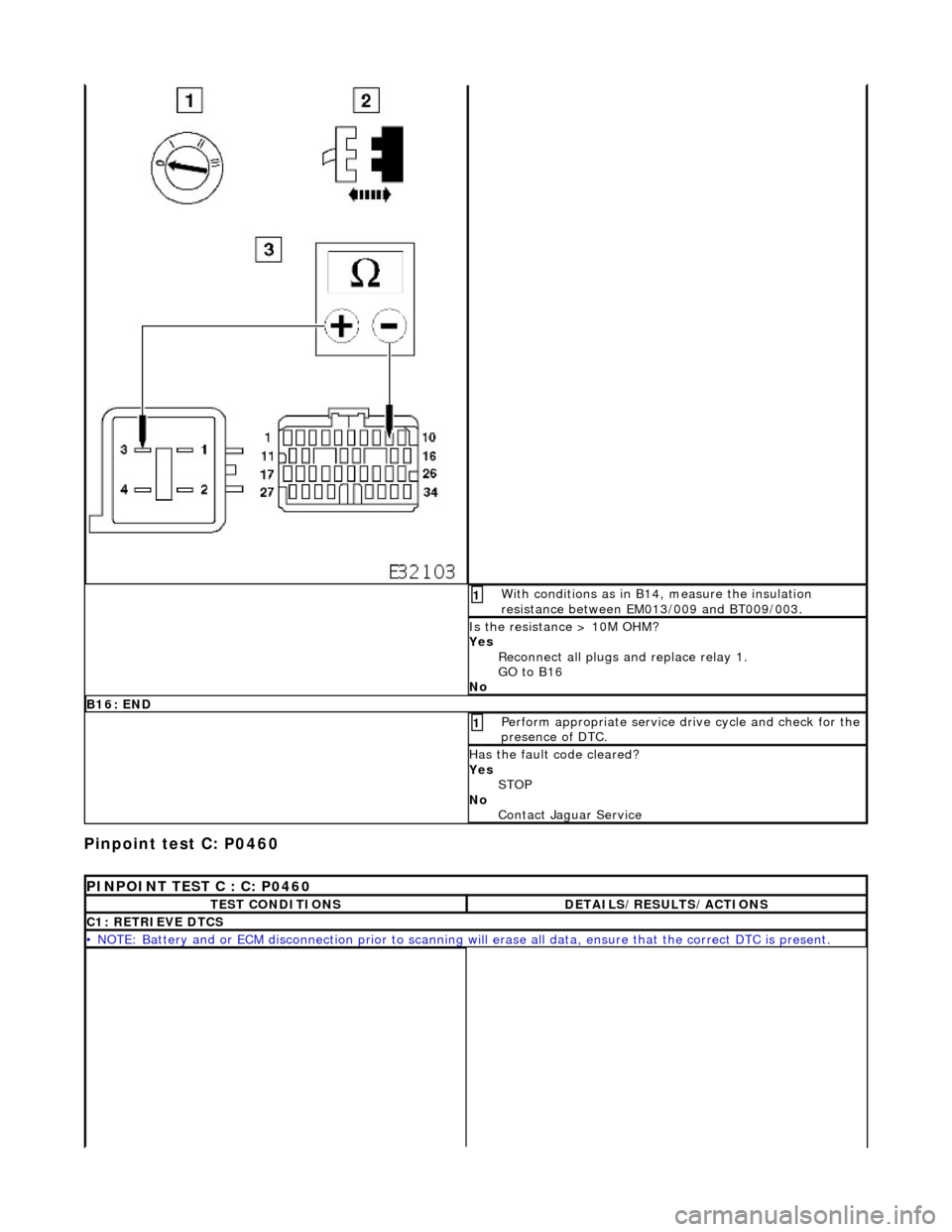
Pinpoint test C: P0460
Wi
th conditions as in B14, measure the insulation
resistance between EM013/009 and BT009/003.
1
I s
the resistance > 10M OHM?
Yes Reconnect all plugs and replace relay 1.
GO to B16
No
B 16:
END
Perform
a
ppropriate service drive cycle and check for the
presence of DTC.
1
Has th
e fault code cleared?
Yes STOP
No Contact Jaguar Service
PI
NPOINT TEST C : C: P0460
T
E
ST CONDITIONS
D
E
TAILS/RESULTS/ACTIONS
C1
: RETRIEVE DTC
S
•
NOTE
: Battery and or ECM disconnection prior to scanning wi
ll erase all data, ensure that the correct DTC is present.
Page 1731 of 2490
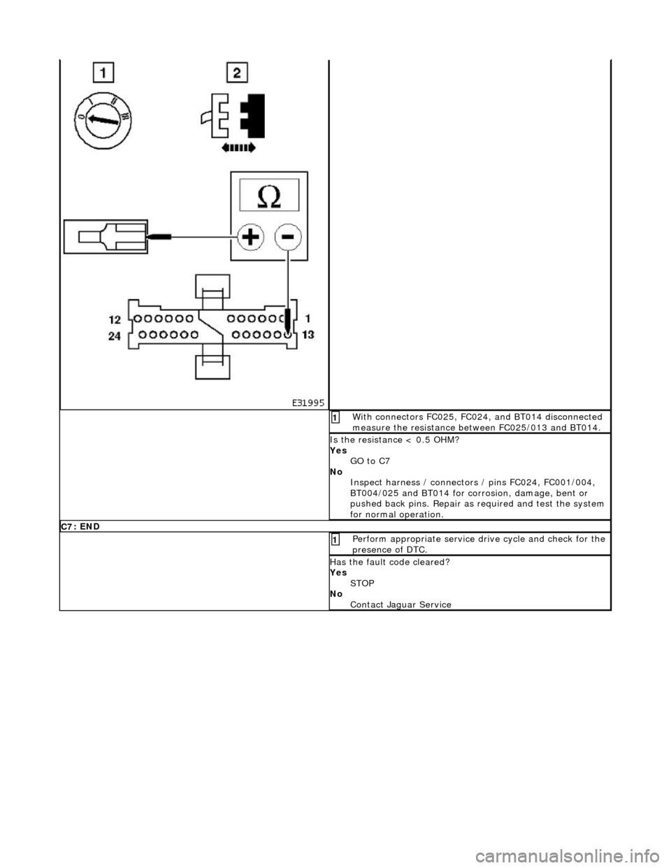
W
ith connectors FC025, FC024, and BT014 disconnected
measure the resistance between FC025/013 and BT014.
1
I
s the resistance < 0.5 OHM?
Yes GO to C7
No Inspect harness / connectors / pins FC024, FC001/004,
BT004/025 and BT014 for corrosion, damage, bent or
pushed back pins. Repair as required and test the system
for normal operation.
C7
: END
Perform
appropriate service drive cycle and check for the
presence of DTC.
1
Has
the fault code cleared?
Yes STOP
No Contact Jaguar Service
Page 1744 of 2490
Speed Control - Speed
Control
D
iagn
osis and Testing
Pri
n
ciples of operation
The s
p
eed (cruise) control sy
stem is activated by an ON/OFF master switch in the J-gate surround, which has an integral
LED to indicate status.
The steering wheel switches allow the driver to set the speed, increase or decrease the selected speed, cancel and resume
the facility without his/her hand ever leaving the steering wheel
The vehicle speed can be increased an d decreased in increments of 2 kmh (1 mph) by briefly pressing the + or - buttons up
to a maximum of five times.
Alternatively, the + or - button can be held until th e desired speed is reached.
The selected speed (by whichever method) w ill be displayed in the message center.
The system will not function at speeds below 26 kmh (16 mph), and can be cancelled from the master switch, the steering
wheel switches, and by depressing th e brake pedal. The system can be overridden by accelerating as normal.
In
spection and Verification
1.
1. Veri fy the customer concern.
2. 2. Vis
ually inspect for obvious signs of mechanical or electrical damage.
3. 3. If an obvious cause for an observed or reported concern is found, correct the cause (if possible) before proceeding
to the next step.
4. 4. If the cause is not visually evident, verify the symptom, check for DTCs and follow the routines in this section.
Vi
sual Inspection Chart
Diagnostic Trouble Code (D
TC) index
MechanicalElectrical
Throttle body mechan
ism
Throttle body actuator
Module Switch(es) Instrument cluster
DTC
De
scr
iption
Possib
l
e Source
Acti
o
n
P0566Speed
c
ontrol
CANCEL
switch ON fault
Speed
control switches internal steering wheel
short circuit to ground
St
eering wheel cassette reel short circuit to
ground
Cassette reel to ECM circ
uit short circuit to
ground
CANCEL
switch failure (stuck ON)
Fo
r
CANCEL switch circuit
tests,GO to Pinpoint Test A.
P0567Speed c
ontrol
RESUME
switch ON fault
Speed
control switches internal steering wheel
short circuit to ground
St
eering wheel cassette reel short circuit to
ground
Cassette reel to ECM circ
uit short circuit to
ground
RESUME swit
ch failure (stuck ON)
For
RESUME switch circuit
tests,GO to Pinpoint Test B.
P0568Spee
d control switch
ground malfunction
Speed
control switches internal steering wheel
open circuit
St
eering wheel cassette reel open circuit or
high resistance
Cassette reel to ECM ci
rcuit open circuit or high
For
ACCEL/DECEL switch circuit
tests,GO to Pinpoint Test C.
Page 1759 of 2490
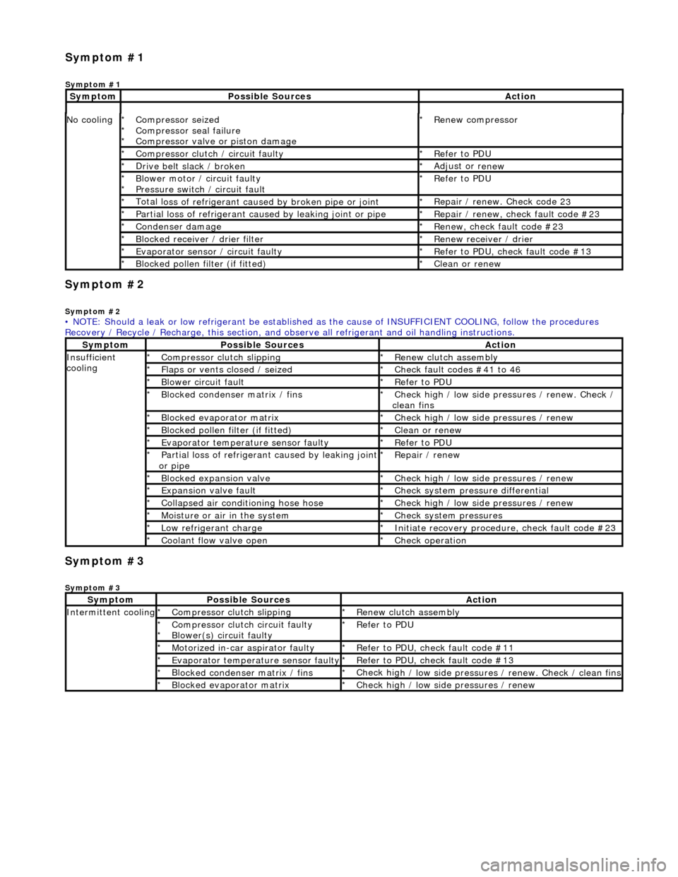
Sym
ptom #2
Sy
mptom #2
Sym
ptom #3
Sy
mptom #3
No
cooling
Compressor sei
zed
Compressor seal failure
Compressor valve or piston damage
*
*
*
R
enew compressor
*
Compressor cl
utch / circuit faulty
*
R
efer to PDU
*
D
rive belt slack / broken
*
Adjust or r
enew
*
B
lower motor / circuit faulty
Pressure switch / circuit fault
*
*
R
efer to PDU
*
Total l
oss of refrigerant caused by broken pipe or joint
*
Repair / renew. Check code 2
3
*
P
artial loss of refrigerant caused by leaking joint or pipe
*
R
epair / renew, check fault code #23
*
Conden
ser damage
*
Re
new, check fault code #23
*
Bl
ocked receiver / drier filter
*
R
enew receiver / drier
*
Evaporator senso
r / circuit faulty
*
R
efer to PDU, check fault code #13
*
Bl
ocked pollen filter (if fitted)
*
Cle
an or renew
*
• NOTE: Should a leak or low refrigerant be established as the cause of INSUFFICIENT COOL ING, follow the procedures
Recovery / Recycle / Recharge, this section, and ob serve all refrigerant and oil handling instructions.
Sy
mptom
Possib
le Sources
Acti
on
Insuffi
cient
cooling
Compre
ssor clutch slipping
*
R
enew clutch assembly
*
Fl
aps or vents closed / seized
*
Check f
ault codes #41 to 46
*
Bl
ower circuit fault
*
R
efer to PDU
*
Bl
ocked condenser matrix / fins
*
Check hig
h / low side pr
essures / renew. Check /
clean fins
*
Bl
ocked evaporator matrix
*
Check hig
h / low side
pressures / renew
*
Bl
ocked pollen filter (if fitted)
*
Cle
an or renew
*
Evaporator temp
erat
ure sensor faulty
*
R
efer to PDU
*
P
artial loss of refrigerant caused by leaking joint
or pipe
*
R
epair / renew
*
Blocked expan
sion valve
*
Check hig
h / low side
pressures / renew
*
Expans
ion valve fault
*
Chec
k system pres
sure differential
*
C
ollapsed air conditioning hose hose
*
Check hig
h / low side
pressures / renew
*
Moi
sture or air in the system
*
Chec
k system pressures
*
Low r
efrigerant charge
*
Initiate recovery
procedure, check fault code #23
*
Coo
lant flow valve open
*
Chec
k operation
*
Sy
mptom
Possib
le Sources
Acti
on
Int
ermittent cooling
Compre
ssor clutch slipping
*
R
enew clutch assembly
*
Compressor cl
utch circuit faulty
Blower(s) circuit faulty
*
*
R
efer to PDU
*
Motorized in-car aspirator faulty
*
R
efer to PDU, check fault code #11
*
Evaporator temp
erature sensor faulty
*
R
efer to PDU, check fault code #13
*
Bl
ocked condenser matrix / fins
*
Check hig
h / low side pressures / renew. Check / clean fins
*
Bl
ocked evaporator matrix
*
Check hig
h / low side
pressures / renew
*
Sym
ptom #1
Sy
mptom #1
Sy
mptom
Possib
le Sources
Acti
on
Page 1760 of 2490
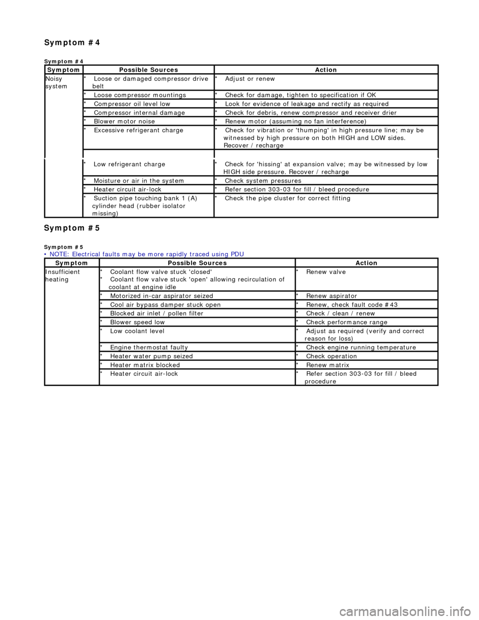
Symp
tom #5
Sy
m
ptom #5
Low r
e
frigerant charge
*
Check f or 'hissi
ng' at expansion
valve; may be witnessed by low
HIGH side pressure. Recover / recharge
*
Moi
s
ture or air in the system
*
Chec k syst
em pressures
*
Heat er ci
rcuit air-lock
*
R e
fer section 303-03 for fill / bleed procedure
*
Suct ion
pipe touching bank 1 (A)
cylinder head (rubber isolator
missing)
*
Check the pi
pe cluster for correct fitti
ng
*
• NOTE: Electrical faults may be more rapidly traced using PDU
Sym
ptom
Possib
l
e Sources
Acti
o
n
Insuffi
ci
ent
heating
Coo l
ant flow valve stuck 'closed'
Coolant flow valve stuck 'open' allowing recirculation of
coolant at engine idle
*
*
Re
new v
alve
*
Motorized in-car aspirator sei zed
*R e
new aspirator
*
Coo l
air bypass damper stuck open
*
Re new,
check fault code #43
*
B l
ocked air inlet / pollen filter
*
Chec k / cl
ean / renew
*
B l
ower speed low
*
Check performance range
*
Low cool ant
level
*
Adjust as req u
ired (verify and correct
reason for loss)
*
Engine
t
hermostat faulty
*
Check engine r u
nning temperature
*
Heater water pump seized
*Chec k op
eration
*
Heater ma trix
blocked
*
Re new m
atrix
*
Heater circui t
air-lock
*
R e
fer section 303-03 for fill / bleed
procedure
*
Sym
p
tom #4
Sym
ptom #4
Sy
m
ptom
Possib
l
e Sources
Acti
o
n
No
i
sy
system
Loose or damaged compressor drive
belt
*Adjust or r
e
new
*
Loose compressor mountings
*Check f o
r damage, tighten to specification if OK
*
Compressor oil level l
ow
*
Look for evidence of l
eakag
e and rectify as required
*
Compressor internal dama ge
*Check f o
r debris, renew compressor and receiver drier
*
B l
ower motor noise
*
Re new m
otor (assuming no fan interference)
*
Excessive refrige rant charge
*Check f o
r vibration or 'thumping'
in high pressure line; may be
witnessed by high pressure on both HIGH and LOW sides.
Recover / recharge
*