park assist JAGUAR X308 1998 2.G Workshop Manual
[x] Cancel search | Manufacturer: JAGUAR, Model Year: 1998, Model line: X308, Model: JAGUAR X308 1998 2.GPages: 2490, PDF Size: 69.81 MB
Page 46 of 2490
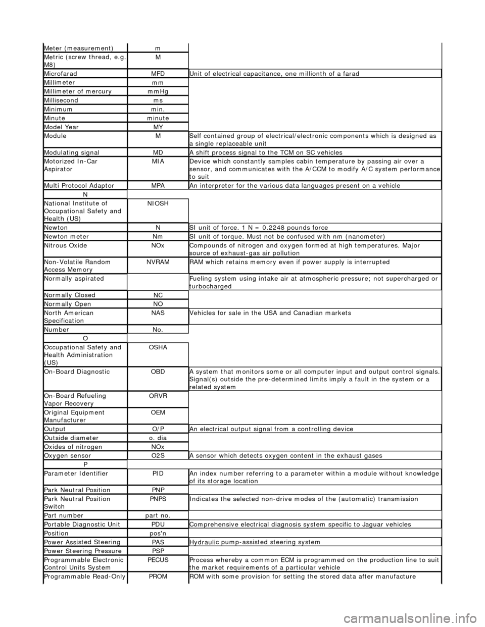
Meter (measurement)m
Me
tric (screw thread, e.g.
M8)
M
MicrofaradMFDUni t
of electrical capacitance, one millionth of a farad
Mi
ll
imeter
mm
Mi
ll
imeter of mercury
mm
Hg
Mill
isecond
ms
Min
i
mum
mi
n.
Min u
te
minut
e
Model YearMY
ModuleMSelf
contained group of electrical/electronic components which is designed as
a single replaceable unit
Modulating signalMDA sh
ift process signal to the TCM on SC vehicles
Motorized In
-Car
AspiratorMIAD e
vice which constantly samples cabi
n temperature by passing air over a
sensor, and communicates with the A/ CCM to modify A/C system performance
to suit
Mult i Prot
ocol Adaptor
MPAAn i
n
terpreter for the various data
languages present on a vehicle
N
Nati
onal Institute of
Occupational Safety and
Health (US)
NIO S
H
Ne
wto
n
NSI unit of force. 1
N = 0.224
8 pounds force
Ne
wto
n meter
NmSI unit of torque. Must not be
co
nfused with nm (nanometer)
Ni
tr
ous Oxide
NO
xCompounds of nit rogen and oxygen fo rmed at high temperatures. Major
sourc
e of exhaust-gas air pollution
No
n
-Volatile Random
Access Memory
NVR A
M
R
A
M which retains memory even
if power supply is interrupted
Normal
ly aspirated
F
u
eling system using intake air at atmo
spheric pressure; not supercharged or
turbocharged
N ormal
ly Closed
NC
N
o
rmally Open
NO
No
r
th American
Specification
NASVehicles f or sal
e in the USA and Canadian markets
Nu
mbe
r
No
.
O
Oc
cupational Safety and
Health Administration
(US)
OS H
A
O
n
-Board Diagnostic
OB
DA system that moni
tors some or all co
mputer input and output control signals.
Signal(s) outside the pre-de termined limits imply a fault in the system or a
related system
O n
-Board Refueling
Vapor Recovery
OR V
R
O
riginal
Equipment
Manufacturer
OE M
Outp
ut
O/
PAn electrical o u
tput signal from a controlling device
Ou
ts
ide diameter
o.
d
ia
O
xides of
nitrogen
NO
x
Oxygen senso
r
O2
SA s
ensor which detects oxygen content in the exhaust gases
P
Parameter Identifi
erPIDAn in
dex number referring to a parame
ter within a module without knowledge
of its storage location
Park N e
utral Position
PN
P
Park N e
utral Position
Switch
PN PSIndic
ates the selected non-drive modes of the (automatic) transmission
Part numberpart no.
Portable Diag
nostic Un
it
PD
UCompre hen
sive electrical diagnosis system specific to Jaguar vehicles
Posi
ti
on
po
s'n
Power As si
sted Steering
PASHydraul
i
c pump-assisted steering system
Power Steer
i
ng Pressure
PSP
Programmable Elect
r
onic
Control Units System
PECU SProcess whereb y
a common ECM is progra
mmed on the production line to suit
the market requirements of a particular vehicle
Programmable Read-O
nly
PROMRO
M with some provision for setting
the stored data after manufacture
Page 309 of 2490
Brake System - General Inform
ation - Brake System
D
iagnosis and Testing
Principles of Operations
The brake system operates by transferring effort applied to th e brake pedal, by the driver to the brakes at each wheel.
The braking effort is distributed to each wheel, using a hydraulic system. The system is assisted using a vacuum brake
booster that reduces pedal effort for a given hydraulic pressure. The parking brake operates on the rear wheels and is
applied using a hand operated control.
I
nspection and Verification
•
NOTE: Prior to carrying out any diagno
sis, make sure that the brake system warning indicator is functional.
Visually examine the front and rear tire and wheel assemblies for damage such as un even wear patterns, tread worn out or
sidewall damage. Verify the tires are th e same size, type and, where possible, same manufacture. Replace the damaged
wheel or excessively worn tire. For a dditional information, refer toSection 204
-0
4 Wheels and Tires
.
W
heels and tires must be cleared of an
y foreign matter and tire pressures ad justed to the correct specification.
If the tires exhibit uneven wear or feathering, the cause must be corrected. Check the steering and suspension components
for damage or wear and, if ne cessary, check and adjust front wheel alignment. For additional information, refer toSection
204
-00 Suspen
sion System
- General Informati
on
.
Road Test
V
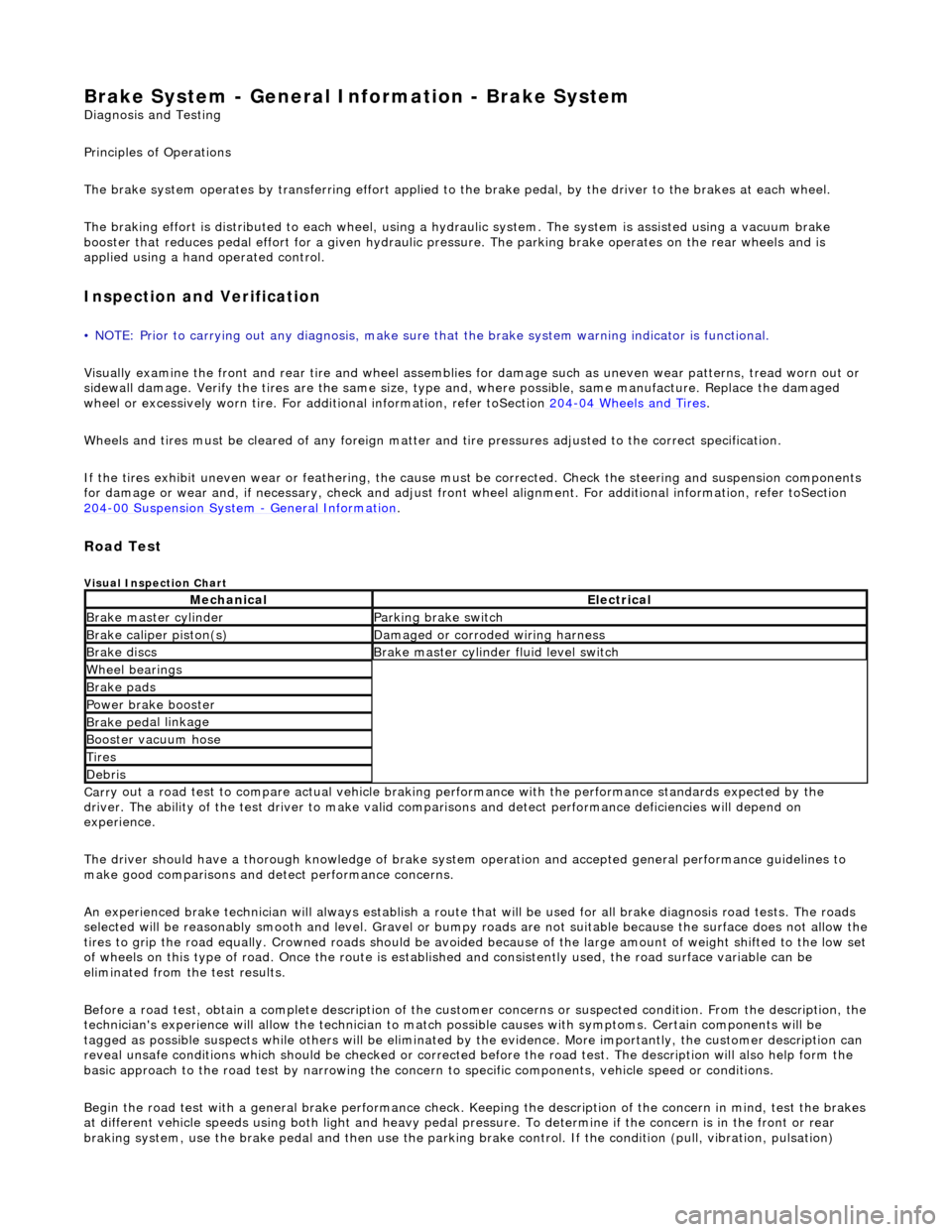
isual Inspection Chart
Carr
y out a road test to compare actual vehicle braking performance with the
performance standards expected by the
driver. The ability of the test driver to make valid compar isons and detect performance deficiencies will depend on
experience.
The driver should have a thorough knowledge of brake system operation and accepted general performance guidelines to
make good comparisons and de tect performance concerns.
An experienced brake technician will always establish a route that will be used for all br ake diagnosis road tests. The roads
selected will be reasonably smooth and level. Gravel or bump y roads are not suitable because the surface does not allow the
tires to grip the road equally. Crowned roads should be avoide d because of the large amount of weight shifted to the low set
of wheels on this type of road. Once th e route is established and consistently used, the road surface variable can be
eliminated from the test results.
Before a road test, obtain a complete description of the customer concerns or suspec ted condition. From the description, the
technician's experience will allow the te chnician to match possible causes with symptoms. Certain components will be
tagged as possible suspects while others wi ll be eliminated by the evidence. More importantly, the customer description can
reveal unsafe conditions which should be ch ecked or corrected before the road test. The description will also help form the
basic approach to the road test by narrowing the concern to specific components, vehicle speed or conditions.
Begin the road test with a general brake performance check. Keeping the description of the concern in mind, test the brakes
at different vehicle speeds using both ligh t and heavy pedal pressure. To determine if the concern is in the front or rear
braking system, use the brake pe dal and then use the parking brake control. If the condition (pull, vibration, pulsation)
MechanicalElectrical
Brake m
aster cylinder
Parkin
g brake switch
Brake ca
liper piston(s)
D
amaged or corroded wiring harness
Brake di
scs
B
rake master cylinder fluid level switch
Wh
eel bearin
gs
Brake pads
Power brake booster
Brake ped
al linkage
Boost
er vacuum hose
Tire
s
De
bris
Page 318 of 2490
Comp
onent Tests
Bra
k
e Booster
1.
1. Chec k all
hoses and connections. All unused vacuum connectors should be capped. Hoses and their connections
should be correctly secured and in good condition with no holes and no collapsed areas. Inspect the valve on the
brake booster for damage.
2. 2. Check the hydraulic brake system for leaks or low fluid.
3. 3. With the transmission in PARK, stop the engine and apply the parking brake. Pump the brake pedal several times
to exhaust all vacuum in the system.
4. 4. With the engine switched off and all vacuum in the system exhausted, appl y the brake pedal and hold it down.
Start the engine. If the vacuum system is operating, the brake pedal will tend to move downward under constant
foot pressure. If no motion is felt, the vacuum booster system is not functioning.
5. 5. Remove the vacuum hose from the brake booster. Manifold vacuum should be available at the brake booster end
of the hose with the engine at idle speed and the transm ission in PARK or NEUTRAL. Make sure that all unused
vacuum outlets are correctly capped, hose connectors are correctly secured and vacuum hoses are in good
condition. When it is established that manifold vacuum is available to the brake booster, connect the vacuum hose
to the brake booster and repeat Step 3. If no downward movement of the brake pedal is felt, install a new brake
booster.
6. 6. Operate the engine for a minimum of 10 seconds at a fast idle. Stop the engine and allow the vehicle to stand for
10 minutes. Then, apply th e brake pedal with approximately 89 N ( 20lb) of force. The pedal feel (brake
application) should be the same as that noted with the engine running. If the brake pedal feels hard (no power
assist), install a new valve and then re peat the test. If the brake pedal still feels hard, in stall a new brake booster.
If the brake pedal movement feels spongy, bleed the brak e system. For additional information, refer to General
Procedures in this section.
Bra k
e Master Cylinder
Usual
l
y, the first and strongest
indicator of anything wrong in the brake syst em is a feeling through the brake pedal. In
diagnosing the condition of the brake master cylinder, check pedal feel as evidence of a brake concern. Check for brake
warning lamp illumination and the brake fluid le vel in the brake master cylinder reservoir.
Normal Conditio
ns
The fo
llowing conditions are considered norm
al and are not indications that the brake master cylinder is in need of repair.
New bra
ke systems are designed to produc
e a pedal effort that is not as hard as in the past. Complaints of light
pedal efforts should be compared to the pedal effort s of another vehicle of the same model and year.
The fl
uid level will fall with brake pad wear.
Abnormal Conditions
•
NOTE: Prior to carrying out any diag
nosis, make sure the brake system warning indicator is functional.
Changes in the brake pedal feel or brake pedal travel are in dicators that something could be wrong in the brake system. The
diagnostic procedure and techniques use brake pedal feel, warning indicator illu mination and low brake fluid level as
indicators to diagnosing brake system co ncerns. The following conditions are cons idered abnormal and indicate that the
brake master cylinder is in need of repair:
Brake ped a
l goes down fast. Th
is could be caused by an ex ternal or internal leak.
Brake pedal goes down slowly
. This could be
caused by an internal or external leak.
Brak
e pedal is low or feels spongy. This condition may be ca
used by no fluid in the brake master cylinder, reservoir
Page 469 of 2490
Buzz (E
lectrical)
A
different steering buzz can be caused by
pulse width modulated (PWM) electric actuators used in variable assist steering
systems. This buzz is felt by turning the ignition key to run without starting the engine and holding onto the steering wheel.
In extreme cases, the buzz can be felt with the engine running also.
Column/Steering Wheel
Shake
Column shake is a low f
requenc
y vertical vibration excited by primary engine vibrations.
Nibble (Shimm
y)
Steeri
ng nibble is a rotary oscillation or
vibration of the steering wheel, which can be excited at a specific vehicle speed.
Nibble is driven by wheel and tire imbalance exciting a suspensi on recession mode, which then translates into steering gear
travel and finally steering wheel nibble.
Shudder (Judd
er)
Shudder i
s a low frequency oscillation of th
e entire steering system (tire, wheels, st eering gear and linkage, etc.) when the
vehicle is steered during static-park or at low sp eeds. Shudder is very dependent on road surface.
Torque Ri
pple
Torque rippl
e is a concern with Electric Power Steering (EPS) sy
stems. Torque ripple is most evident at static-park steering
the wheel very slowly from lock to lock. Torque ripple is primarily caused by motor commutation.
Torque/Veloc
ity Variation
(Phasing/Effort Cycling)
Steeri
ng wheel torque variation oc
curring twice in one revolution is normally as a result of problems with the lower steering
column (intermediate shaft), but foul cond itions generally result in either constant stiffnes s or single point stiffness.
Depending upon the orientation of the joints, the steering can fe el asymmetric (torque falling off in one direction and rising
in the other) or else it can simply have pronounced peaks and troughs as the steering moves from lock to lock.
Wheel Fight
(Kick Back)
W
heel fight is excess feedback of sudden road forces through th
e steering system and back to the driver. It is evaluated at
all vehicle speeds over cobblestones, rough roads, and potholes . The tires, wheels, and suspension generate forces into the
steering systems. Steering friction, hydraulic damping, hydr aulic compliance, mechanical compliance, steering ratio, and
assist gain all affect how much is transmitted to the driver.
Stee
ring Linkage
CAUTI
ON: Steering gear boots must be
handled carefully to avoid damage. Use new clamps when installing steering
gear boots.
Inspect the boots for cuts, deterioration, tw isting or distortion. Check the steering gear boots to make sure they are tight.
Install new boots or clamps as necessary.
• NOTE: The following steps must be carried out with assistance.
1. 1. With the wheels in the straight ahead po sition, gently turn the steering wheel to the left and the right to check for
free play.
2. 2. Free play should be between 0 and 6 mm (0 and 0.24 in) at the steering wheel rim. If the free play exceeds this
limit, either the ball joints are worn, the lower steering column joints are worn or the backlash of the steering gear
is excessive.
Page 489 of 2490
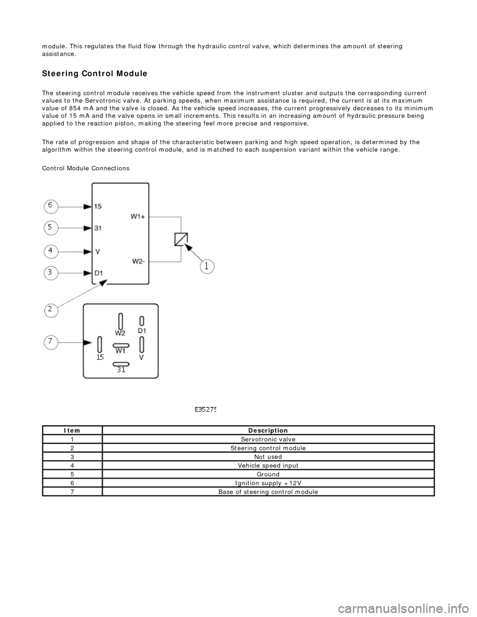
modul
e. This regulates the fluid flow
through the hydraulic control valve, wh ich determines the amount of steering
assistance.
Steering Control Module
The steering control
module re
ceives the vehicle speed from the instrument cluster and outputs the corresponding current
values to the Servot ronic valve. At parking speeds, wh en maximum assistance is required , the current is at its maximum
value of 854 mA and the valve is closed. As the vehicle speed increases, the current progressively decreases to its minimum
value of 15 mA and the valve opens in sma ll increments. This results in an increasing amount of hydraulic pressure being
applied to the reaction piston, making the steering feel more precise and responsive.
The rate of progression and shape of the characteristic between parking and high speed operation, is determined by the
algorithm within the steering control module, and is matched to each suspension variant within the vehicle range.
Control Module Connections
It
em
De
scription
1Servotronic valve
2Steeri
ng control module
3No
t used
4Vehi
cle speed input
5Ground
6Ignition su
pply +12V
7Base of
steering control module
Page 1869 of 2490
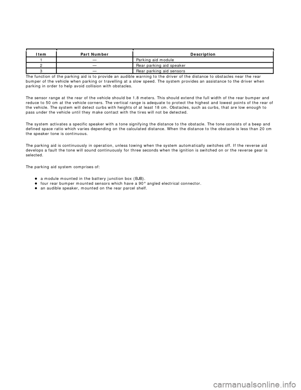
The functi
on of the parking aid is to prov
ide an audible warning to the driver of the distance to obstacles near the rear
bumper of the vehicle when parking or travelling at a slow sp eed. The system provides an assistance to the driver when
parking in order to help avoid collision with obstacles.
The sensor range at the rear of the vehicl e should be 1.8 meters. This should extend the full width of the rear bumper and
reduce to 50 cm at the vehicle co rners. The vertical range is adequate to protec t the highest and lowest points of the rear of
the vehicle. The system will detect curbs with heights of at least 18 cm. Obstacles, such as curbs, that are low enough to
pass under the vehicle until they make contact with the tires will not be detected.
The system activates a specific speaker with a tone signifying the distance to the obstacle. The tone consists of a beep and
defined space ratio which varies depending on the calculated distance. When the distance to the obstacle is less than 20 cm
the speaker tone is continuous.
The parking aid is continuously in operation, unless towing wh en the system automatically switches off. If the reverse aid
develops a fault the tone will sound continuously for three seconds when the igni tion is switched on or the reverse gear is
selected.
The parking aid system comprises of:
a
module mounted in the batte
ry junction box (BJB).
fou
r rear bumper mounted sensors which have a 90° angled electrical connector.
an audible speaker, moun
ted on
the rear parcel shelf.
It
em
Par
t Number
De
scription
1—Parkin
g aid module
2—Rear
parking aid speaker
3—Rear
parking aid sensors