204-04 JAGUAR X308 1998 2.G Workshop Manual
[x] Cancel search | Manufacturer: JAGUAR, Model Year: 1998, Model line: X308, Model: JAGUAR X308 1998 2.GPages: 2490, PDF Size: 69.81 MB
Page 222 of 2490
Remova
l
2
05-2
34 (JD 550-1)
1. CAUTION: Replacement of nuts and bolts: Various
thread-locking devices are used on nuts and bolts throughout the
vehicle. These devices restrict the number of times a nut or bolt
can be used. See section 100-00 for information.
Release handbrake.
2. Ra
ise the vehicle on a four-post lift.
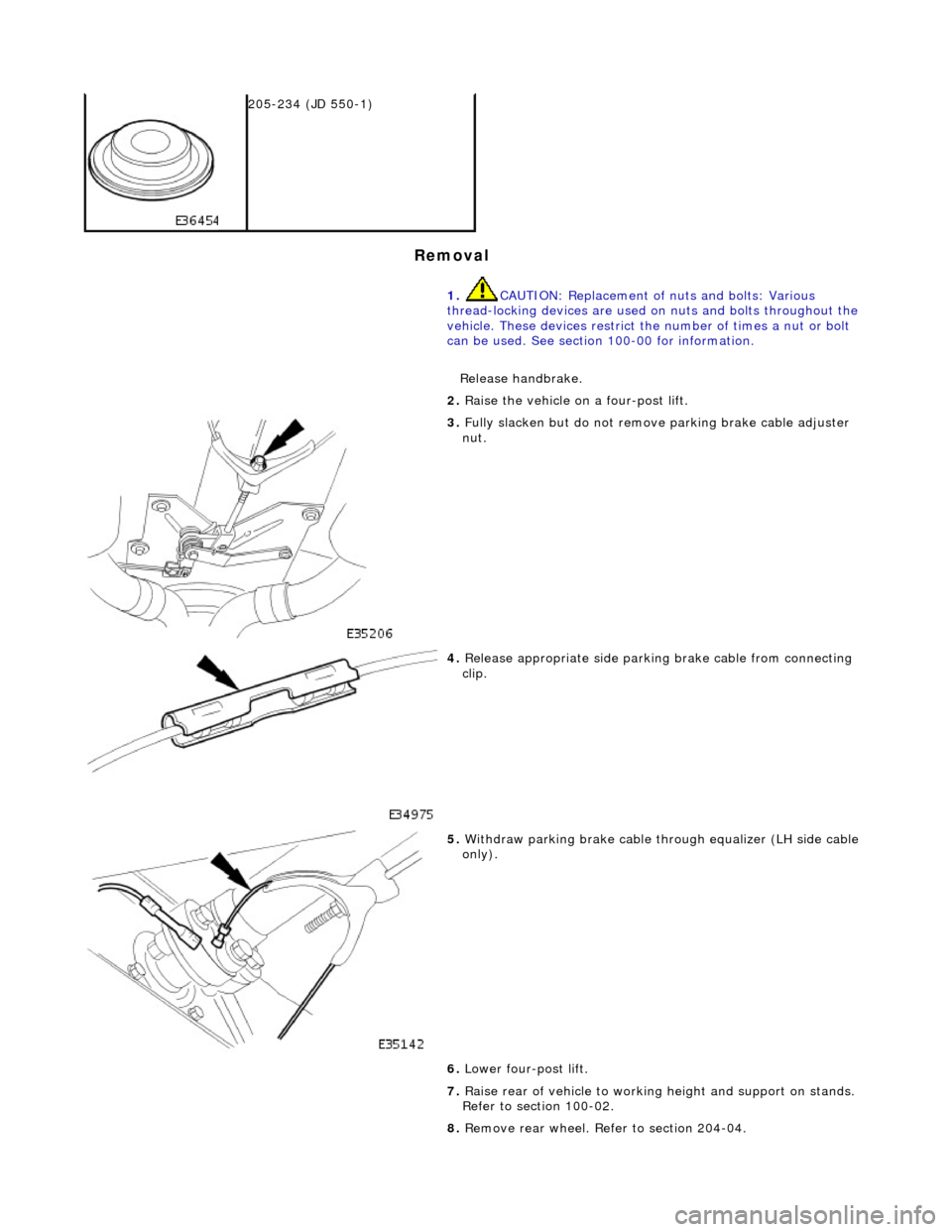
3. Fully slacken bu
t do not remove parking brake cable adjuster
nut.
4. Relea s
e appropriate side parkin
g brake cable from connecting
clip.
5. With draw parkin
g brake cable th
rough equalizer (LH side cable
only).
6. Lower four-post lift.
7. Raise rear of vehicle to workin g height and support on stands.
Refer to section 100-02.
8. Remove rear wheel. Refer to section 204-04.
Page 235 of 2490
35
.
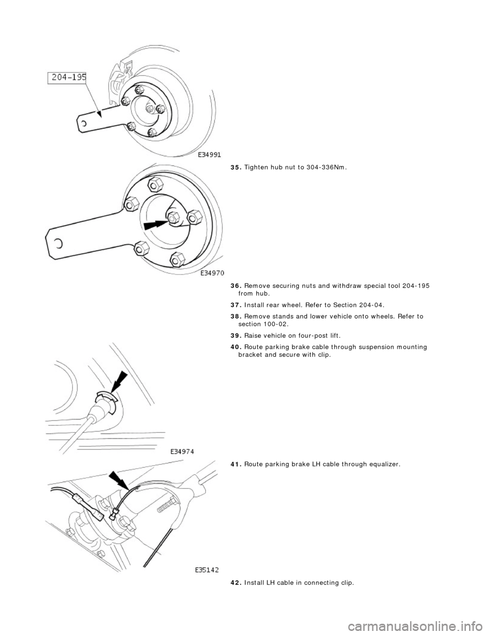
Tighten hub nut to 304-336Nm.
36. Remove securing nuts and withdraw special tool 204-195
from hub.
37. Install rear wheel. Refer to Section 204-04.
38. Remove stands and lower vehi cle onto wheels. Refer to
section 100-02.
39. Raise vehicle on four-post lift.
40
.
Route parking brake cable through suspension mounting
bracket and secure with clip.
41
.
Route parking brake LH ca ble through equalizer.
42. Install LH cable in connecting clip.
Page 238 of 2490

clip
.
5. With draw parkin
g brake cable th
rough equalizer (LH side cable
only).
6. Lower four-post lift.
7. Raise rear of vehicle to workin g height and support on stands.
Refer to section 100-02.
8. Remove rear wheel. Refer to section 204-04.
9. Posit i
on special tool (204-1
95) on hub studs and install
securing nuts.
10 . Slac
ken but do not remove hub to axle shaft securing nut.
11. Remove nuts and withdraw special tool (204-195) from hub.
12. Remove rear brake disc. Refer to 70.10.13.
13. Remove parking brake shoe s. Refer to 70.40.05.
14. Remove wheel speed sensor.
Page 247 of 2490
20
.
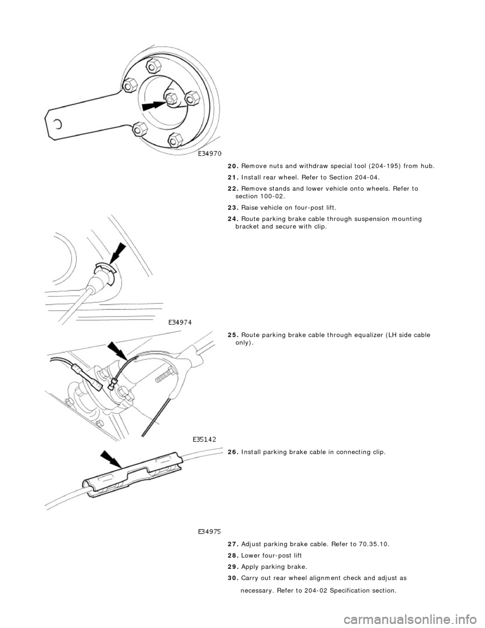
Remove nuts and withdraw special tool (204-195) from hub.
21. Install rear wheel. Refer to Section 204-04.
22. Remove stands and lower vehi cle onto wheels. Refer to
section 100-02.
23. Raise vehicle on four-post lift.
24
.
Route parking brake cable through suspension mounting
bracket and secure with clip.
25
.
Route parking brake cable through equalizer (LH side cable
only).
26
.
Install parking brake cabl e in connecting clip.
27. Adjust parking brake cable. Refer to 70.35.10.
28. Lower four-post lift
29. Apply parking brake.
30. Carry out rear wheel alignm ent check and adjust as
necessary. Refer
t
o 204-02 Specification section.
Page 249 of 2490

cli
p.
5. With
draw parking brake cable th
rough equalizer (LH side cable
only).
6. Lower four-post lift.
7. Raise rear of vehicle to workin g height and support on stands.
Refer to section 100-02.
8. Remove rear wheel. Refer to section 204-04.
9. Posit
ion special tool (204-1
95) on hub studs and install
securing nuts.
10
.
Slacken but do not remove hub to axle shaft securing nut.
11. Remove securing nuts from stud s and withdraw special tool
(204-195) from hub.
12. Remove rear brake disc. Refer to 70.10.13.
13. Remove parking brake shoe s. Refer to 70.40.05.
14. Remove wheel speed sensor.
Page 258 of 2490
24
. R
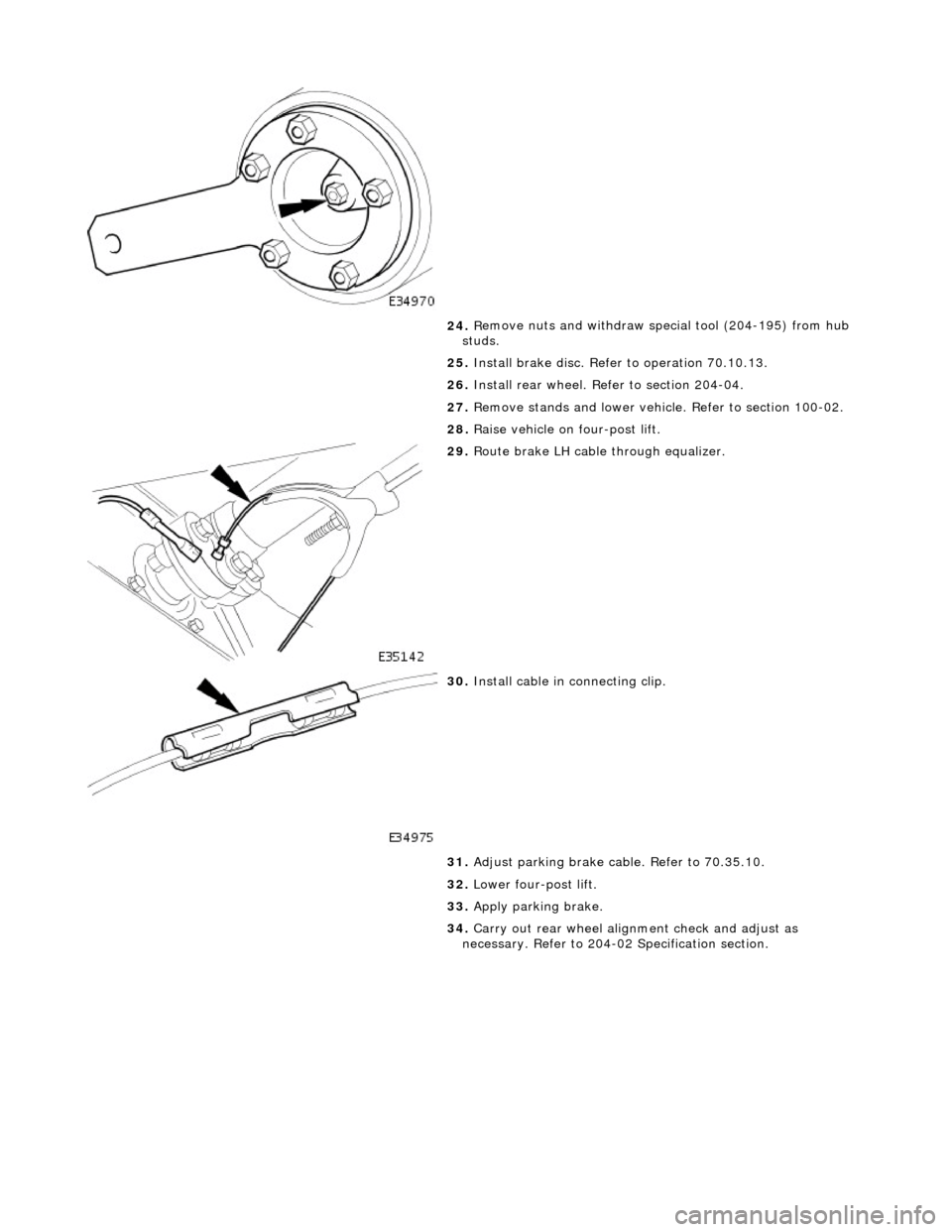
emove nuts and withdraw special tool (204-195) from hub
studs.
25. Install brake disc. Refer to operation 70.10.13.
26. Install rear wheel. Refer to section 204-04.
27. Remove stands and lower vehicl e. Refer to section 100-02.
28. Raise vehicle on four-post lift.
29 . Rout
e brake LH cable through equalizer.
30 . Inst
all cable in connecting clip.
31. Adjust parking brake cable. Refer to 70.35.10.
32. Lower four-post lift.
33. Apply parking brake.
34. Carry out rear wheel alignm ent check and adjust as
necessary. Refer to 204-02 Specification section.
Page 259 of 2490
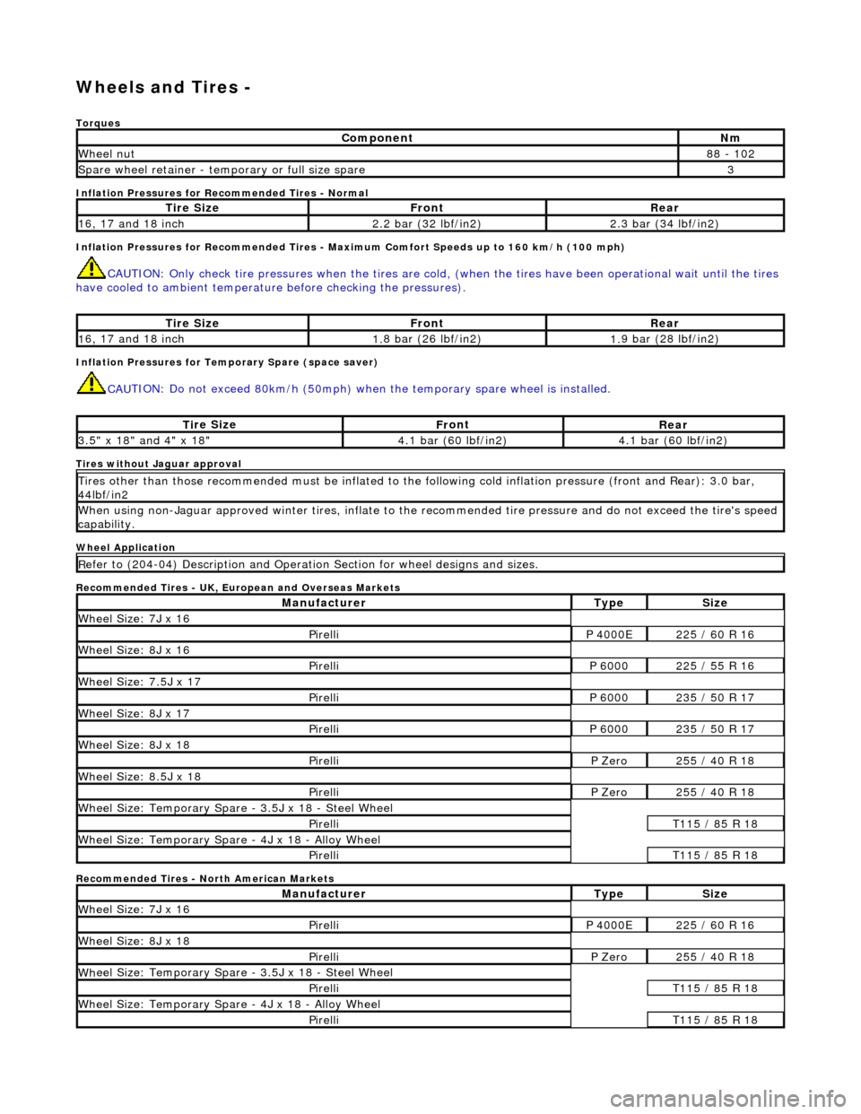
W
heels and Tires -
Torq
ues
Inflation Pressures for Recommended Tires - Normal
Inflation Pressures for Recommended Tires - Maxi mum Comfort Speeds up to 160 km/h (100 mph)
CAUTI
ON: Only check tire pressures when
the tires are cold, (when the tires have been operational wait until the tires
have cooled to ambient temperature before checking the pressures).
Inf
lation Pressures for Temporary Spare (space saver)
CAU
TION: Do not exceed 80km/h (50mph) when the temporary spare
wheel is installed.
Tires
without Jaguar approval
Wheel Application
Recommended Tires - UK, European and Overseas Markets
Recommended Tires - North American Markets
Com
ponent
Nm
Wh
eel nut
8
8 - 102
Spare wheel r
etainer - temporary or full size spare
3
Ti
re Size
Fr
ont
Rear
1
6, 17 and 18 inch
2.
2 bar (32 lbf/in2)
2.
3 bar (34 lbf/in2)
Ti
re Size
Fr
ont
Rear
1
6, 17 and 18 inch
1.
8 bar (26 lbf/in2)
1.
9 bar (28 lbf/in2)
Ti
re Size
Fr
ont
Rear
3.
5" x 18" and 4" x 18"
4.
1 bar (60 lbf/in2)
4.
1 bar (60 lbf/in2)
Ti
res other than those recommended must be inflated to the following cold
inflation pressure (front and Rear): 3.0 bar,
44lbf/in2
Wh
en using non-Jaguar approved winter ti
res, inflate to the recommended tire pressure and do not exceed the tire's speed
capability.
R
efer to (204-04) Description and Operation Section for wheel designs and sizes.
Manufact
urer
Ty
pe
Si
ze
W
heel Size: 7J x 16
Pire
lli
P 40
00E
2
25 / 60 R 16
W
heel Size: 8J x 16
Pire
lli
P 60
00
2
25 / 55 R 16
Wh
eel Size: 7.5J x 17
Pire
lli
P 60
00
2
35 / 50 R 17
W
heel Size: 8J x 17
Pire
lli
P 60
00
2
35 / 50 R 17
W
heel Size: 8J x 18
Pire
lli
P Ze
ro
2
55 / 40 R 18
Wh
eel Size: 8.5J x 18
Pire
lli
P Ze
ro
2
55 / 40 R 18
Wh
eel Size: Temporary Spare - 3.5J x 18 - Steel Wheel
Pire
lli
T1
15 / 85 R 18
W
heel Size: Temporary Spare - 4J x 18 - Alloy Wheel
Pire
lli
T1
15 / 85 R 18
Manufact
urer
Ty
pe
Si
ze
W
heel Size: 7J x 16
Pire
lli
P 40
00E
2
25 / 60 R 16
W
heel Size: 8J x 18
Pire
lli
P Ze
ro
2
55 / 40 R 18
Wh
eel Size: Temporary Spare - 3.5J x 18 - Steel Wheel
Pire
lli
T1
15 / 85 R 18
W
heel Size: Temporary Spare - 4J x 18 - Alloy Wheel
Pire
lli
T1
15 / 85 R 18
Page 263 of 2490
O
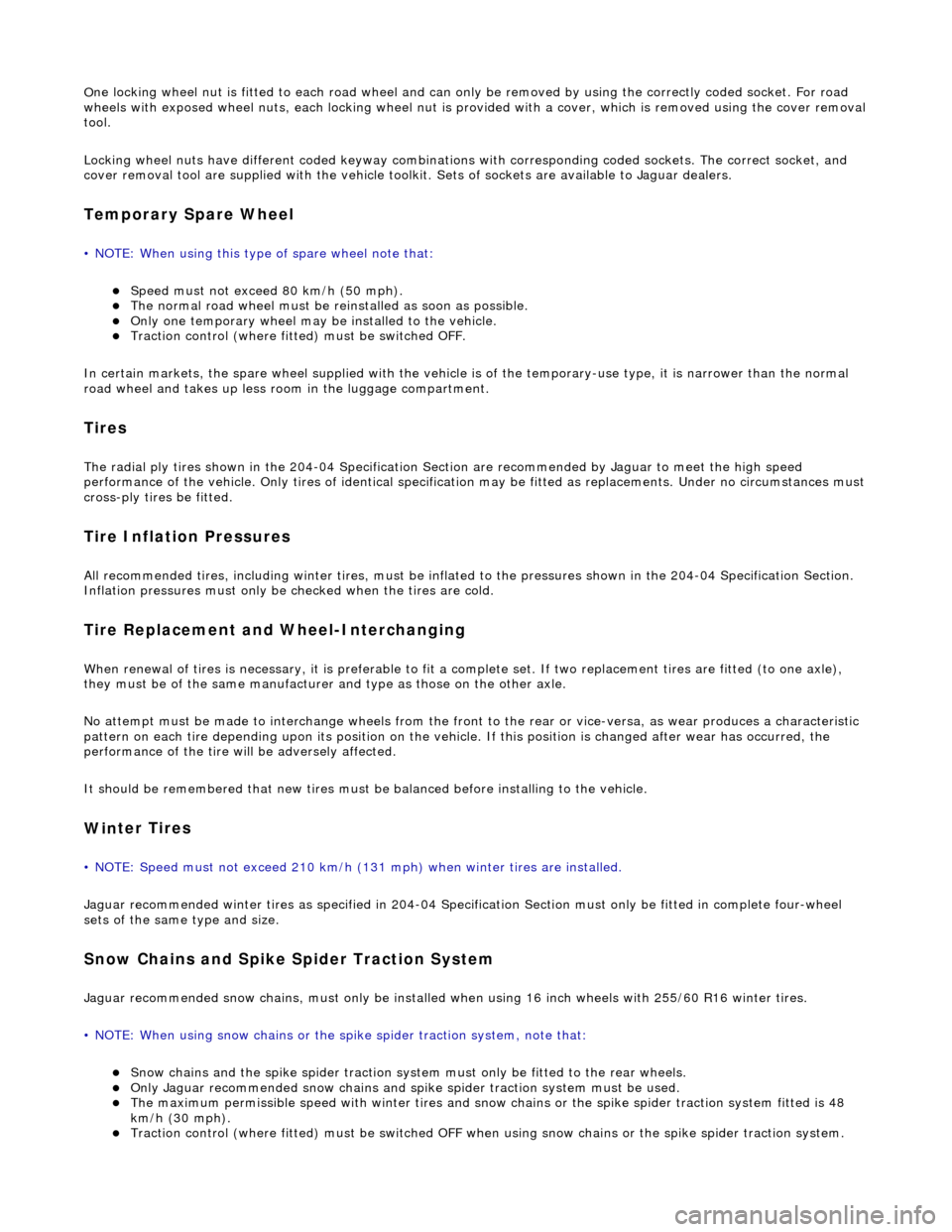
ne locking wheel nut is fitted to each road wheel and can on
ly be removed by using the correctly coded socket. For road
wheels with exposed wheel nuts, each locking wheel nut is provided with a cover, which is removed using the cover removal
tool.
Locking wheel nuts have different coded keyway combinations with corresponding coded sockets. The correct socket, and
cover removal tool are supplied with the vehicle toolkit. Sets of sockets are available to Jaguar dealers.
Temporary Spare Wheel
•
NOTE: When using this type of spare wheel note that:
Speed
must not exceed 80 km/h (50 mph).
The normal ro
ad wheel must be reinstalled as soon as possible.
On
ly one temporary wheel may be installed to the vehicle.
Tracti
on control (where fitted
) must be switched OFF.
In certain markets, the spare wheel supplied with the vehicle is of the temporary-use type, it is narrower than the normal
road wheel and takes up less room in the luggage compartment.
Tire
s
The
radial ply tires shown in the 204-04
Specification Section are recommended by Jaguar to meet the high speed
performance of the vehicle. Only tires of identical specification may be fitted as replacements. Unde r no circumstances must
cross-ply tires be fitted.
Tire Inflation Pressures
Al
l recommended tires, including winter tire
s, must be inflated to the pressures shown in the 204-04 Specification Section.
Inflation pressures must only be checked when the tires are cold.
Tire Replac
ement and Wheel-Interchanging
W
hen renewal of tires is necessary, it is
preferable to fit a complete set. If two replacement tires are fitted (to one axle),
they must be of the same manufacturer and type as those on the other axle.
No attempt must be made to interchange wh eels from the front to the rear or vice-versa, as wear produc es a characteristic
pattern on each tire depending upon its po sition on the vehicle. If this position is changed after wear has occurred, the
performance of the tire w ill be adversely affected.
It should be remembered that new tires must be balanced befo re installing to the vehicle.
Win
ter Tires
•
NOTE: Speed must not exceed 210 km/h (131 mph) when winter tires are installed.
Jaguar recommended winter tires as specified in 204-04 Specification Section must only be fitted in complete four-wheel
sets of the same type and size.
Snow Chains and Spike Spider Traction System
Jagu
ar recommended snow chains, must on
ly be installed when using 16 inch wheels with 255/60 R16 winter tires.
• NOTE: When using snow chains or the spike spider traction system, note that:
Snow ch
ains and the spike spider
traction system must only be fitted to the rear wheels.
O
nly Jaguar recommended snow chains and spik
e spider traction system must be used.
The m
aximum permissible speed with winter tires and snow chains or the spike spider traction system fitted is 48
km/h (30 mph).
Tracti
on control (where fitted) must be
switched OFF when using snow chains or the spike spider traction system.
Page 333 of 2490
Position the gauge so that the pointer contacts the hub face.
Slowly rotate the hub one revolution, the hub run-out must not exceed the specification. Refer to
Specification Section <<204-01>>.
If the hub exceeds the maximum run-out specification replace the hub. Refer to Section <<204-01>>.
9. NOTE:
Make sure the brake disc and hub mating surfaces are clean.
If the hub run-out is within specification replace brake discs. Refer to procedure 70.10.13.
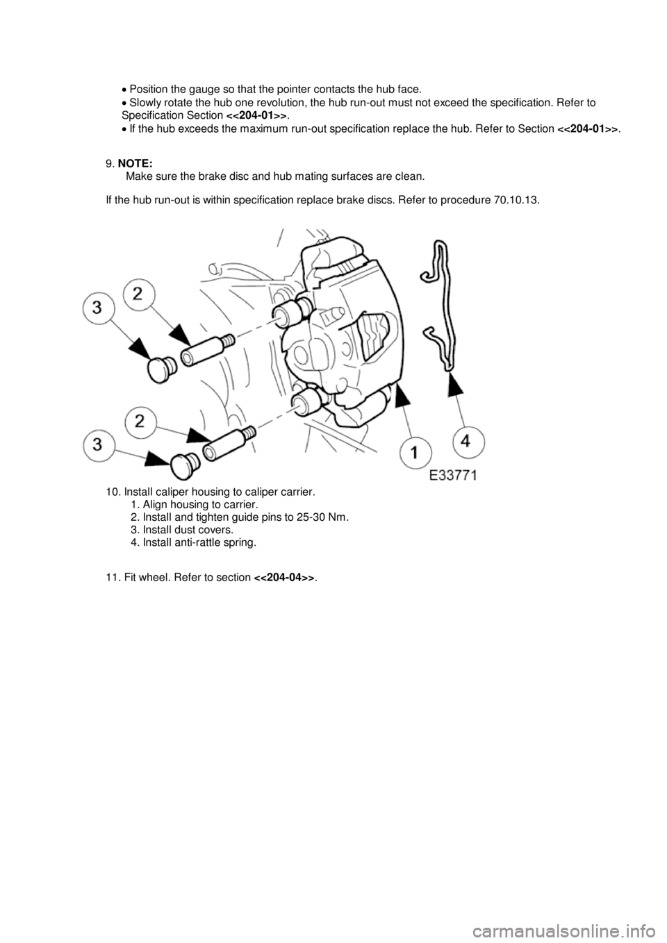
1
0. Install caliper housing to caliper carrier.
1. Align housing to carrier.
2. Install and tighten guide pins to 25-30 Nm.
3. Install dust covers.
4. Install anti-rattle spring.
11. Fit wheel. Refer to section <<204-04>>.
Page 338 of 2490

13
.
CA
UTION:
Retracting the caliper piston may cause the fluid reservoir to over-flow. Remove brake fluid
spillage immediately from paint work with clean water.
CA
UTION:
Note condition of pins and replace if necessary.
Install brake pads to caliper. Slowly retract caliper pistons.
1. Install pads.
2. Position anti-rattle spring.
3. Install pins - make sure pin collets are fully engaged into caliper.
14. Fit wheel. Refer to section <<204-04>>.