303-01 JAGUAR X308 1998 2.G Workshop Manual
[x] Cancel search | Manufacturer: JAGUAR, Model Year: 1998, Model line: X308, Model: JAGUAR X308 1998 2.GPages: 2490, PDF Size: 69.81 MB
Page 560 of 2490
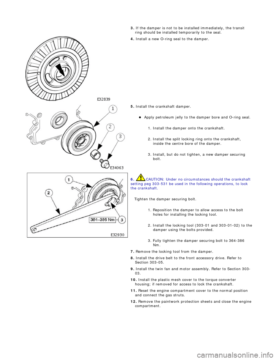
3.
If
the damper is not to be installed immediately, the transit
ring should be installed temporarily to the seal.
4. Install a new O-ri
ng seal to the damper.
5. Instal
l the crankshaft damper.
Apply petroleum jelly to the damper
bore and O-ring seal.
1. Install the damper onto the crankshaft.
2. Install the split locking ring onto the crankshaft,
inside the centre bo re of the damper.
3. Install, but do not tigh ten, a new damper securing
bolt.
6. CAUTIO
N: Under no circumstan
ces should the crankshaft
setting peg 303-531 be used in the following operations, to lock
the crankshaft.
Tighten the damper securing bolt. 1. Reposition the damper to allow access to the bolt holes for installing the locking tool.
2. Install the locking tool (303-01 and 303-01-02) to the
damper using the bolts provided.
3. Fully tighten the damper securing bolt to 364-386 Nm.
7. Re
move the locking tool from the damper.
8. Install the drive belt to the fr ont accessory drive. Refer to
Section 303-05.
9. Install the twin fan and motor assembly. Refer to Section 303-
03.
10. Install the plastic mesh cove r to the torque converter
housing; if removed for acce ss to lock the crankshaft.
11. Reset the engine compartment cover to the normal position
and connect the gas struts.
12. Remove the paintwork protection sheets and close the engine
compartment.
Page 596 of 2490
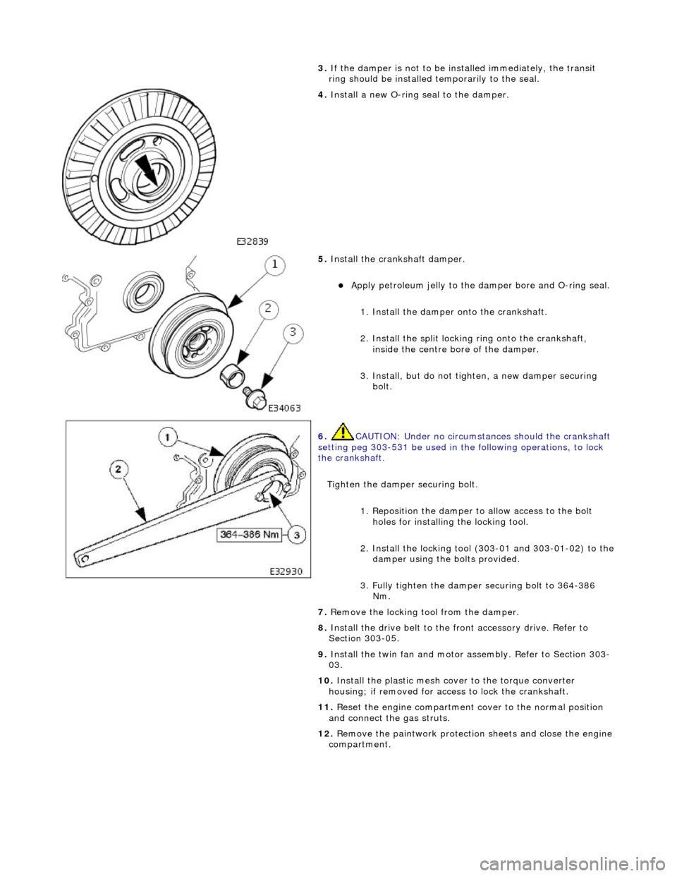
3.
If
the damper is not to be installed immediately, the transit
ring should be installed temporarily to the seal.
4. Install a new O-ri
ng seal to the damper.
5. Instal
l the crankshaft damper.
Apply petroleum jelly to the damper
bore and O-ring seal.
1. Install the damper onto the crankshaft.
2. Install the split locking ring onto the crankshaft,
inside the centre bo re of the damper.
3. Install, but do not tigh ten, a new damper securing
bolt.
6. CAUTIO
N: Under no circumstan
ces should the crankshaft
setting peg 303-531 be used in the following operations, to lock
the crankshaft.
Tighten the damper securing bolt. 1. Reposition the damper to allow access to the bolt holes for installing the locking tool.
2. Install the locking tool (303-01 and 303-01-02) to the
damper using the bolts provided.
3. Fully tighten the damper securing bolt to 364-386 Nm.
7. Re
move the locking tool from the damper.
8. Install the drive belt to the fr ont accessory drive. Refer to
Section 303-05.
9. Install the twin fan and motor assembly. Refer to Section 303-
03.
10. Install the plastic mesh cove r to the torque converter
housing; if removed for acce ss to lock the crankshaft.
11. Reset the engine compartment cover to the normal position
and connect the gas struts.
12. Remove the paintwork protection sheets and close the engine
compartment.
Page 611 of 2490
E
ngine - Cylinder Head LH
In-ve
hicle Repair
Remova
l
CAU
TION: If a replacement cylinder head is to be installed to a
vehicle with variable camshaft timing (VCT) the cylinder head m ust have the
oil gallery blind rivet removed before installation.
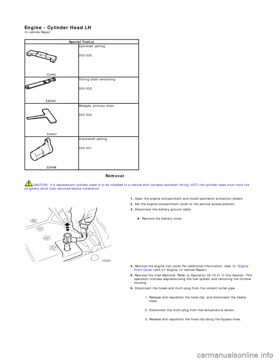
Spe
cial Tool(s)
Cams
haft setting
303-530
Ti
ming chain tensioning
303-532
Wedges, prim
ary chain
303-533
Cr
ankshaft setting
303-531
1.
Open the engine compartment and install paintwork protection sheets.
2. Set the engine compartment cover to the service access position.
3.
Disconnect the battery ground cable.
Re
move the battery cover.
4. Remove the engine fron cover.For additional information, refer to: Engine
Front Cover (303-01 Engi
ne, In-vehicle Repair).
5. Remove the Inlet Manifold. Refer to Operation 30.15.01 in this Section. This operation includes depressurising the fuel system and removing the throttle
housing.
6. Disconnect the hoses and multi-plug from the coolant outlet pipe.
1. Release and reposition the hose clip, and disconnect the heater hose.
2. Disconnect the multi-plug from the temperature sensor.
3. Release and reposition the hose clip along the bypass hose.
Page 618 of 2490
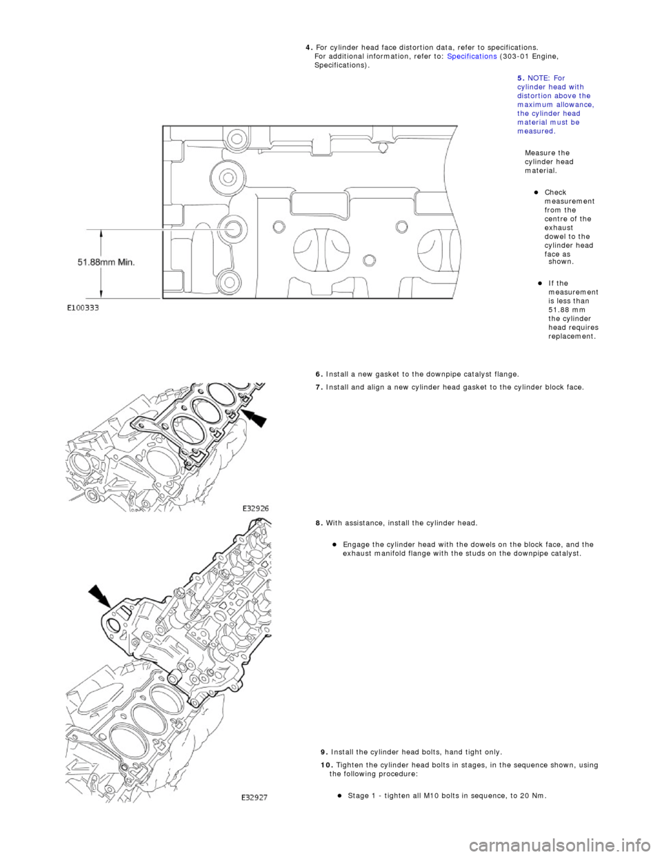
shown
.
If the
m
easurement
is less than
51.88 mm
the cylinder
head requires
replacement.
6.
Install a new gasket to the downpipe catalyst flange.
7.
Install and align a new cylinder head gasket to the cylinder block face.
8.
With assistance, install the cylinder head.
E
ngage t
he cylinder head with the dowels on the block face, and the
exhaust manifold flange with the studs on the downpipe catalyst.
9. Install the cylinder head bolts, hand tight only.
10. Tighten the cylinder head bolts in stages, in the sequence shown, using
the following procedure:
Stage 1 - ti
ghten all M10 bolt
s in sequence, to 20 Nm.
4.
For cylinder head face distortion
data, refer to specifications.
For additional information, refer to: Specifications
(303-01 Engi
ne,
Specifications).
5. NOTE: For
cylinder head with
distortion above the
maximum allowance,
the cylinder head
material must be
measured.
Measure the
cylinder head
material.
Che c
k
measurement
from the
centre of the
exhaust
dowel to the
cylinder head
face as
Page 625 of 2490
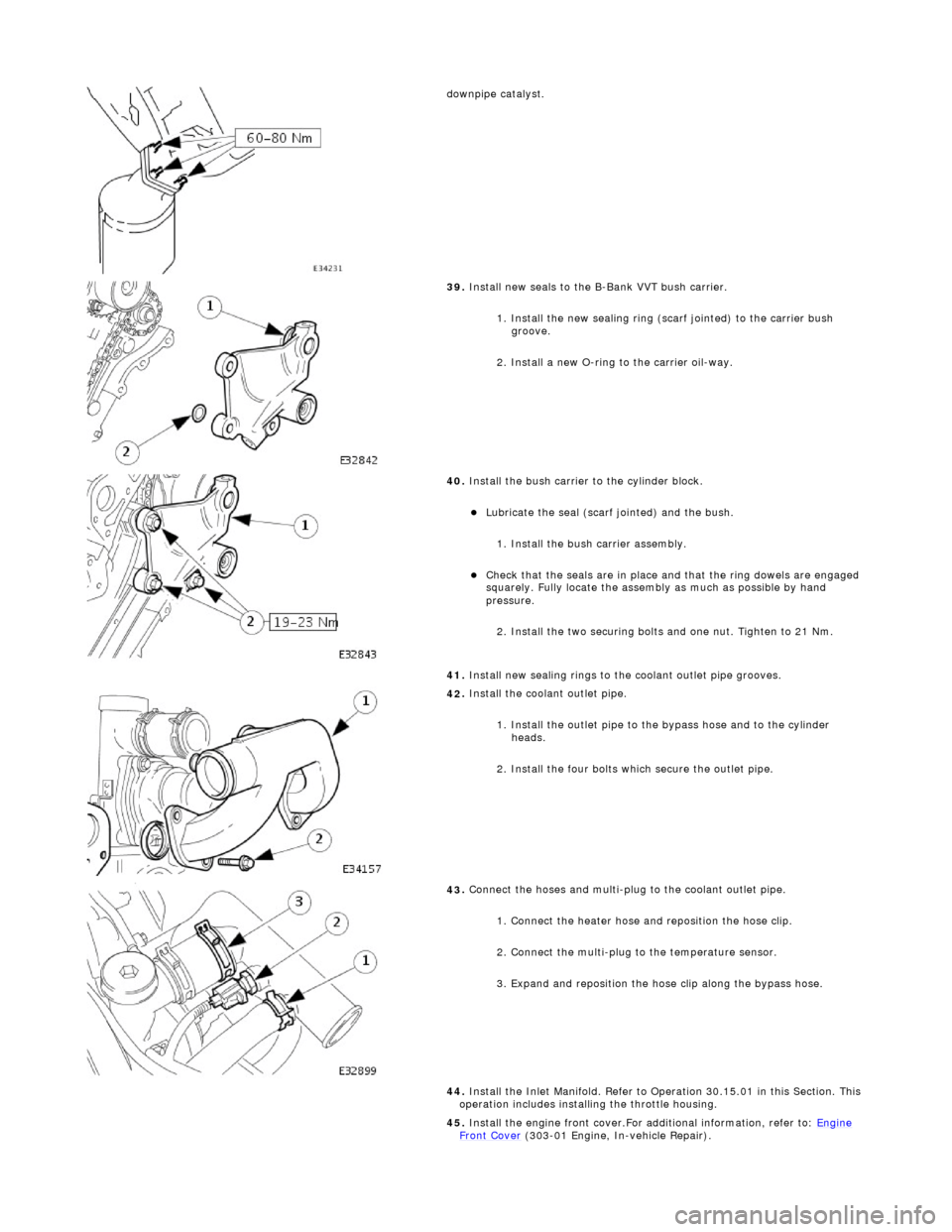
d
ownpipe catalyst.
39
.
Install new seals to the B-Bank VVT bush carrier.
1. Install the new sealing ring (scarf jointed) to the carrier bush groove.
2. Install a new O-ring to the carrier oil-way.
40
.
Install the bush carrier to the cylinder block.
Lu
bricate the seal (scarf
jointed) and the bush.
1. Install the bush carrier assembly.
Chec
k that the seals are
in place and that the ri ng dowels are engaged
squarely. Fully locate the assembly as much as possible by hand
pressure.
2. Install the two securing bolts and one nut. Tighten to 21 Nm.
41. Install new sealing rings to the coolant outlet pipe grooves.
42
.
Install the coolant outlet pipe.
1. Install the outlet pipe to the bypass hose and to the cylinder heads.
2. Install the four bolts which secure the outlet pipe.
43
.
Connect the hoses and multi-plug to the coolant outlet pipe.
1. Connect the heater hose and reposition the hose clip.
2. Connect the multi-plug to the temperature sensor.
3. Expand and reposition the hose clip along the bypass hose.
44. Install the Inlet Manifold. Refer to Operation 30.15.01 in this Section. This
operation includes installing the throttle housing.
45. Install the engine front cover.For additional information, refer to: Engine
Front Cover (303-01 Engi
ne, In-vehicle Repair).
Page 627 of 2490
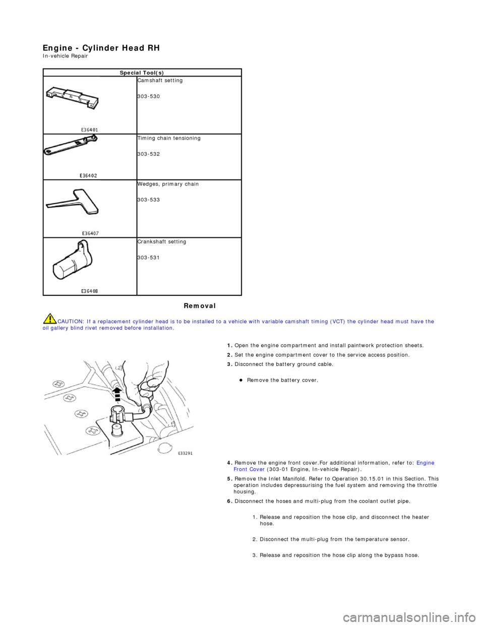
E
ngine - Cylinder Head RH
In-ve
hicle Repair
Remova
l
CAU
TION: If a replacement cylinder head is to be installed to a
vehicle with variable camshaft timing (VCT) the cylinder head m ust have the
oil gallery blind rivet removed before installation.
Spe
cial Tool(s)
Cams
haft setting
303-530
Ti
ming chain tensioning
303-532
Wedges, prim
ary chain
303-533
Cr
ankshaft setting
303-531
1.
Open the engine compartment and install paintwork protection sheets.
2. Set the engine compartment cover to the service access position.
3.
Disconnect the battery ground cable.
Re
move the battery cover.
4. Remove the engine front cover.For additional information, refer to: Engine
Front Cover (303-01 Engi
ne, In-vehicle Repair).
5. Remove the Inlet Manifold. Refer to Operation 30.15.01 in this Section. This operation includes depressurising the fuel system and removing the throttle
housing.
6. Disconnect the hoses and multi-plug from the coolant outlet pipe.
1. Release and reposition the hose clip, and disconnect the heater hose.
2. Disconnect the multi-plug from the temperature sensor.
3. Release and reposition the hose clip along the bypass hose.
Page 641 of 2490
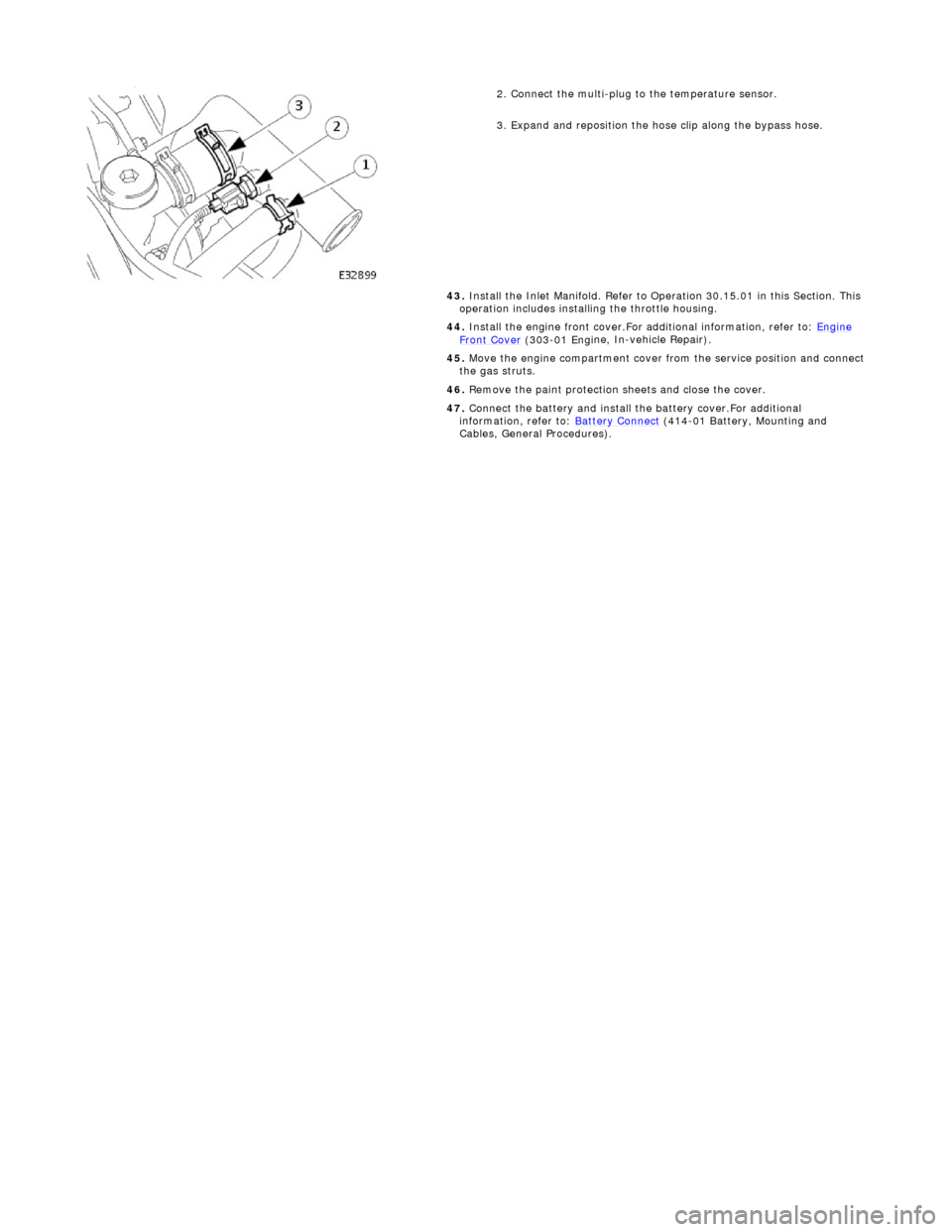
2.
Connect the multi-plug to the temperature sensor.
3. Expand and reposition the hose clip along the bypass hose.
43. Install the Inlet Manifold. Refer to Operation 30.15.01 in this Section. This
operation includes installing the throttle housing.
44. Install the engine front cover.For additional information, refer to: Engine
Front Cover (303-01 Engi
ne, In-vehicle Repair).
45. Move the engine compartment cover from the service position and connect
the gas struts.
46. Remove the paint protection sheets and close the cover.
47. Connect the battery and install th e battery cover.For additional
information, refer to: Battery Connect
(414
-01 Battery, Mounting and
Cables, General Procedures).
Page 1019 of 2490
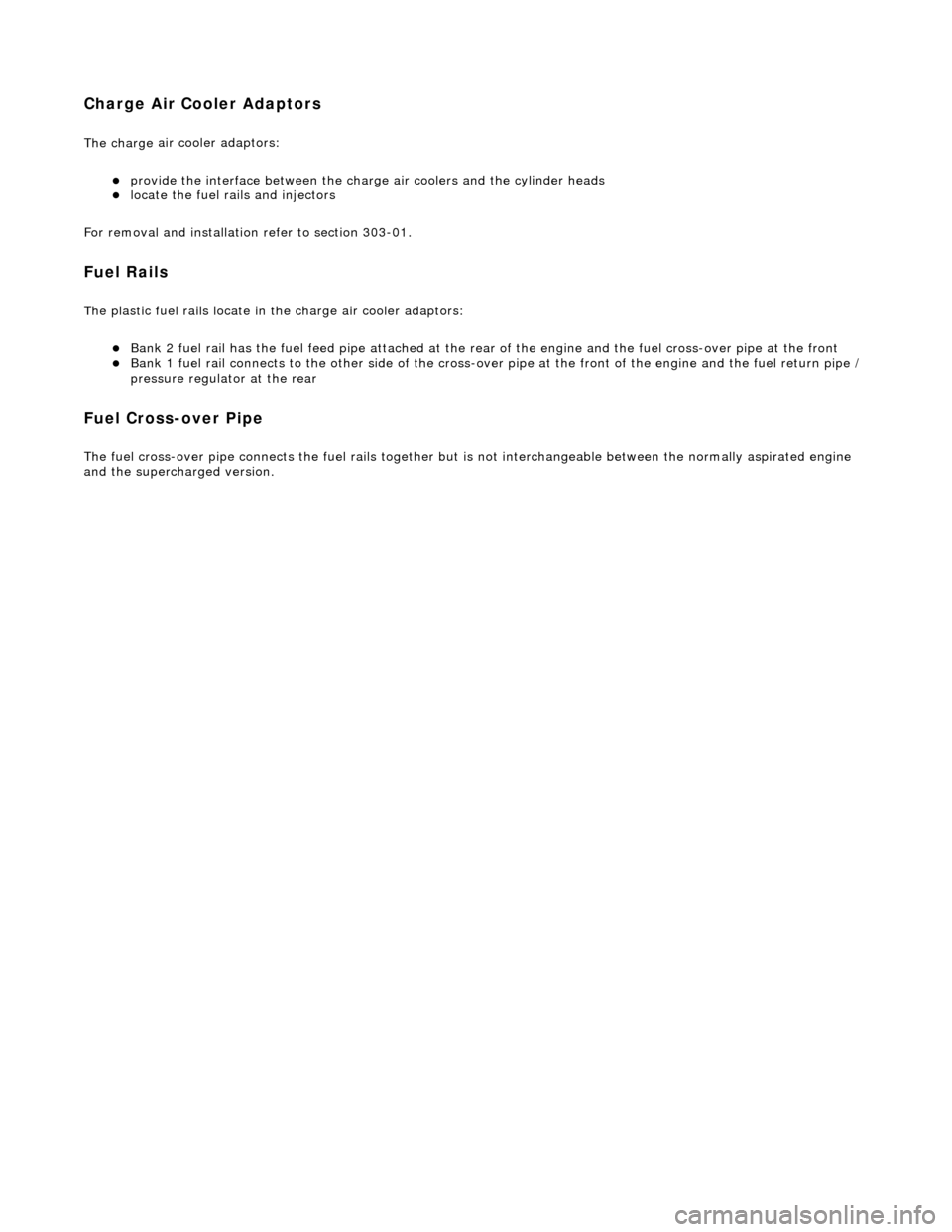
C
harge Air Cooler Adaptors
The charge
air cooler adaptors:
provi
de the interface between the charge air coolers and the cylinder heads
l
ocate the fuel ra
ils and injectors
For removal and installation refer to section 303-01.
Fuel R
ails
The plasti
c fuel rails locate in
the charge air cooler adaptors:
Bank 2 fuel rai
l has the fuel feed pipe attached at the rear
of the engine and the fuel cross-over pipe at the front
Bank 1 fuel rai
l connects to
the other side of the cross-over pipe at the front of the engine and the fuel return pipe /
pressure regulato r at the rear
Fuel C
ross-over Pipe
The fu
el cross-over pipe connects the fuel rails together but is not interchangeable between the normally aspirated engine
and the supercha rged version.
Page 1111 of 2490
the
intake elbow provide connections for vacuum actuators and are also used to redirect emissions into the engine.
On the right-hand side of the elbow a la rge diameter pipe connects to the brake servo. The smaller pipe provides a vacuum
feed to the fuel rail pressure regulator and throttle cruise control system. On the le ft-hand side of the elbow the front pipe
supplies vacuum control for the evaporative emissions system valves.
Emissions from the engine part load breather (bank 2) and pu rged fuel vapor from the EVAP valve are drawn via a common
T piece into the left-hand side of the intake elbow. Re-cir culated exhaust gas enters the intake elbow via the EGR valve
which is mounted directly on the rear of the elbow : where the EGR system is not used, a blanking plate is fitted.
The fuel system, throttle and emission control system s are described more fully in the relevant sections.
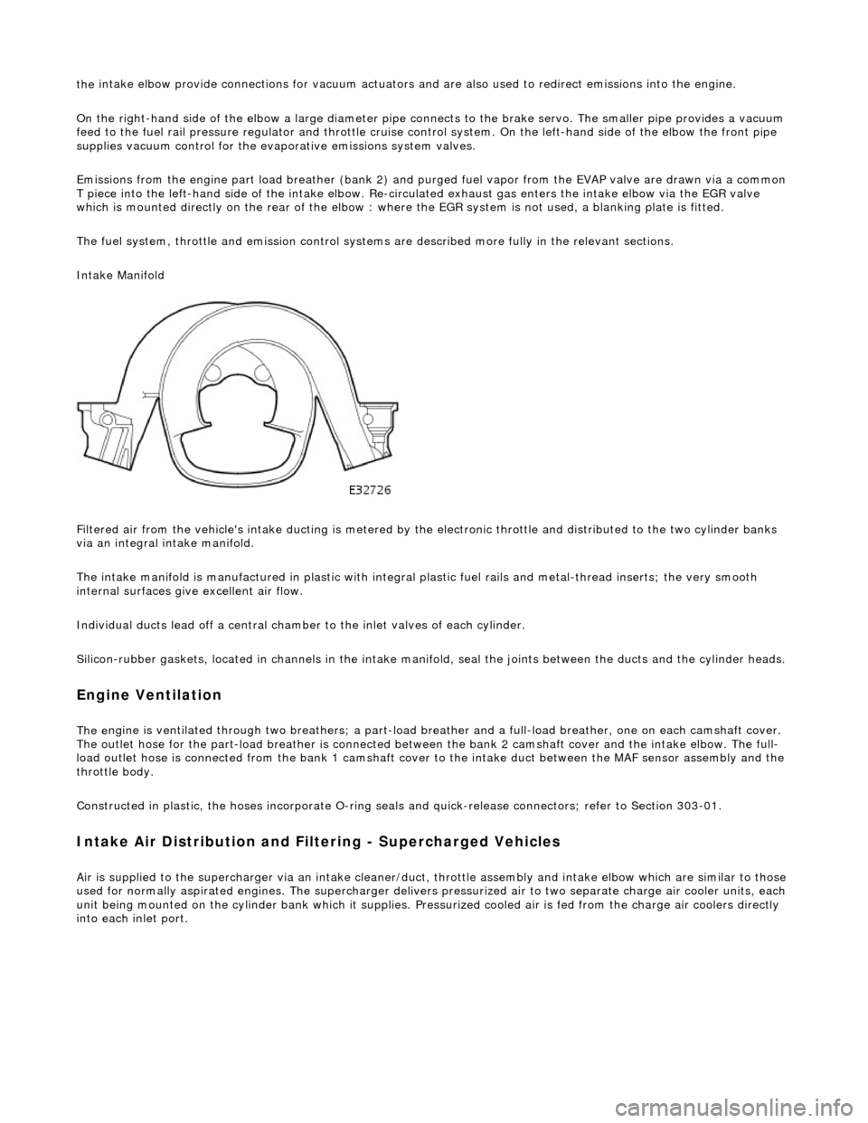
Intake Manifold
Filtered air from the vehicle's intake ducting is metered by th e electronic throttle and distributed to the two cylinder banks
via an integral intake manifold.
The intake manifold is manufactured in plastic with integral plastic fuel rails and metal-thread inserts; the very smooth
internal surfaces give excellent air flow.
Individual ducts lead off a central chamber to the inlet valves of each cylinder.
Silicon-rubber gaskets, loca ted in channels in the intake manifold, seal th e joints between the ducts and the cylinder heads.
Engine Ventilation
The e
ngine is ventilated through two brea
thers; a part-load breather and a full-load breather, one on each camshaft cover.
The outlet hose for the part-load breather is connected between the bank 2 camshaft cover and the intake elbow. The full-
load outlet hose is connected from the bank 1 camshaft cover to the intake duct between the MAF sensor assembly and the
throttle body.
Constructed in plastic, the hoses incorporate O-ring seal s and quick-release connectors; refer to Section 303-01.
I
ntake Air Distribution and Filtering - Supercharged Vehicles
Ai
r is supplied to the supercharger via an
intake cleaner/duct, throttle assembly and intake elbow which are similar to those
used for normally aspirated engines. The su percharger delivers pressurized air to two separate charge air cooler units, each
unit being mounted on the cy linder bank which it supplies. Pr essurized cooled air is fed from the charge air coolers directly
into each inlet port.
Page 1179 of 2490
generates a signal when th
e dr
ive plate passes the sensor
sen
ds the ECM signals indicating crankshaft position and engine speed
is e
ssential for calculating spark timing
En
gine Coolant Temperature (ECT) Sensor
sen
ds the ECM a signal indicating the temperature of the engine coolant
is a t
emperature dependent resistor with a negative temperature coefficient (resistance changes inversely with
respect to temperature) and is constantly monitored by the ECM
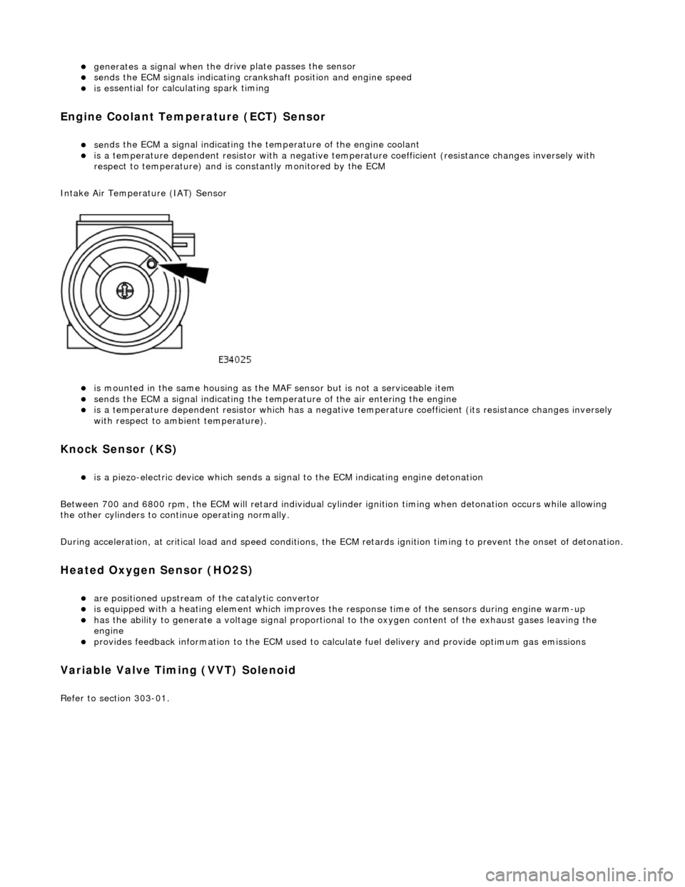
Intake Air Temperature (IAT) Sensor
is m
ounted in the same housing as the MA
F sensor but is not a serviceable item
sen
ds the ECM a signal indicating the temperature of the air entering the engine
is a t
emperature dependent resistor which has a negative
temperature coefficient (its resistance changes inversely
with respect to ambient temperature).
Knock S
ensor (KS)
is a pi
ezo-electric device which sends a signal
to the ECM indicating engine detonation
Between 700 and 6800 rpm, the ECM will retard individual cylinder ignition timing when detonation occurs while allowing
the other cylinders to continue operating normally.
During acceleration, at critical load and speed conditions, the ECM retards ignition timing to prevent the onset of detonation.
H
eated Oxygen Sensor (HO2S)
are
positioned upstream of the catalytic convertor
is equipped with
a heating element wh
ich improves the response time of the sensors during engine warm-up
h
as the ability to generate a voltage signal proportional to the oxygen content of the exhaust gases leaving the
engine
pr
ovides feedback information to the ECM used to calc
ulate fuel delivery and provide optimum gas emissions
Variable V
alve Timing (VVT) Solenoid
R
efer to section 303-01.