Coolant recovery JAGUAR X308 1998 2.G Workshop Manual
[x] Cancel search | Manufacturer: JAGUAR, Model Year: 1998, Model line: X308, Model: JAGUAR X308 1998 2.GPages: 2490, PDF Size: 69.81 MB
Page 900 of 2490

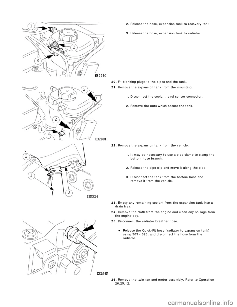
2. Release the hose, expansion tank to recovery tank.
3. Release the hose, expansion tank to radiator.
20. Fit blanking plugs to the pipes and the tank.
21. Remove the expansion tank from the mounting.
1. Disconnect the coolant level sensor connector.
2. Remove the nuts which secure the tank.
22. Remove the expansion tank from the vehicle.
1. It may be necessary to us e a pipe clamp to clamp the
bottom hose branch.
2. Release the pipe clip an d move it along the pipe.
3. Disconnect the tank from the bottom hose and remove it from the vehicle.
23. Empty any remaining coolant from the expansion tank into a
drain tray.
24. Remove the cloth from the engine and clean any spillage from
the engine bay.
25. Disconnect the radiator breather hose.
Release the Quick-Fit hose (radiator to expansion tank)
using 303 - 623, and disconnect the hose from the
radiator.
26. Remove the twin fan and motor assembly. Refer to Operation
26.25.12.
Page 921 of 2490

2
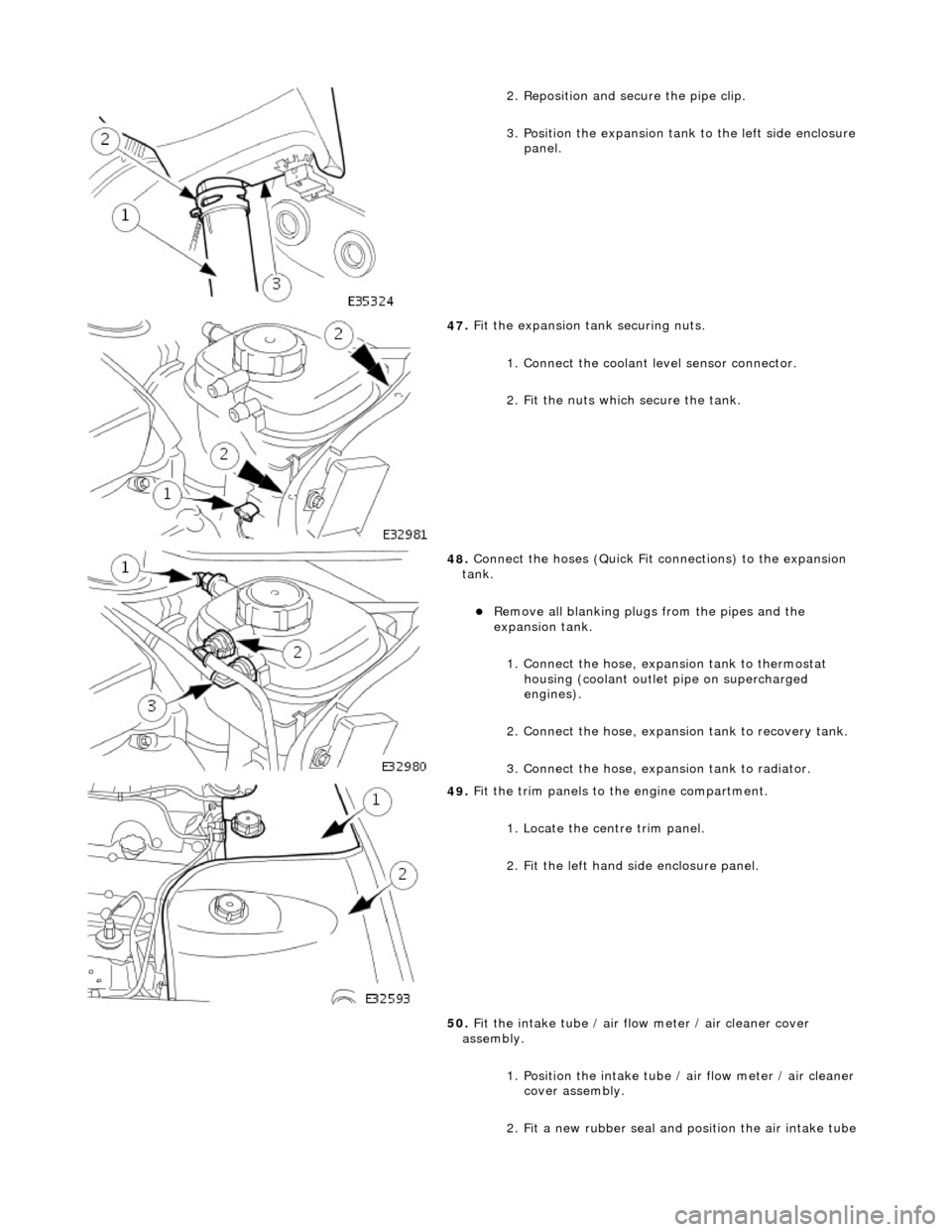
. Reposition and secure the pipe clip.
3. Position the expansion tank to the left side enclosure
panel.
47
.
Fit the expansion tank securing nuts.
1. Connect the coolant level sensor connector.
2. Fit the nuts which secure the tank.
48
.
Connect the hoses (Quick Fit connections) to the expansion
tank.
Remove all blanking plug s
from the pipes and the
expansion tank.
1. Connect the hose, expansion tank to thermostat housing (coolant outlet pipe on supercharged
engines).
2. Connect the hose, expansion tank to recovery tank.
3. Connect the hose, expansion tank to radiator.
49
.
Fit the trim panels to the engine compartment.
1. Locate the centre trim panel.
2. Fit the left hand side enclosure panel.
50. Fit the intake tube / air flow meter / air cleaner cover
assembly.
1. Position the intake tube / air flow meter / air cleaner
cover assembly.
2. Fit a new rubber seal and po sition the air intake tube
Page 925 of 2490

T
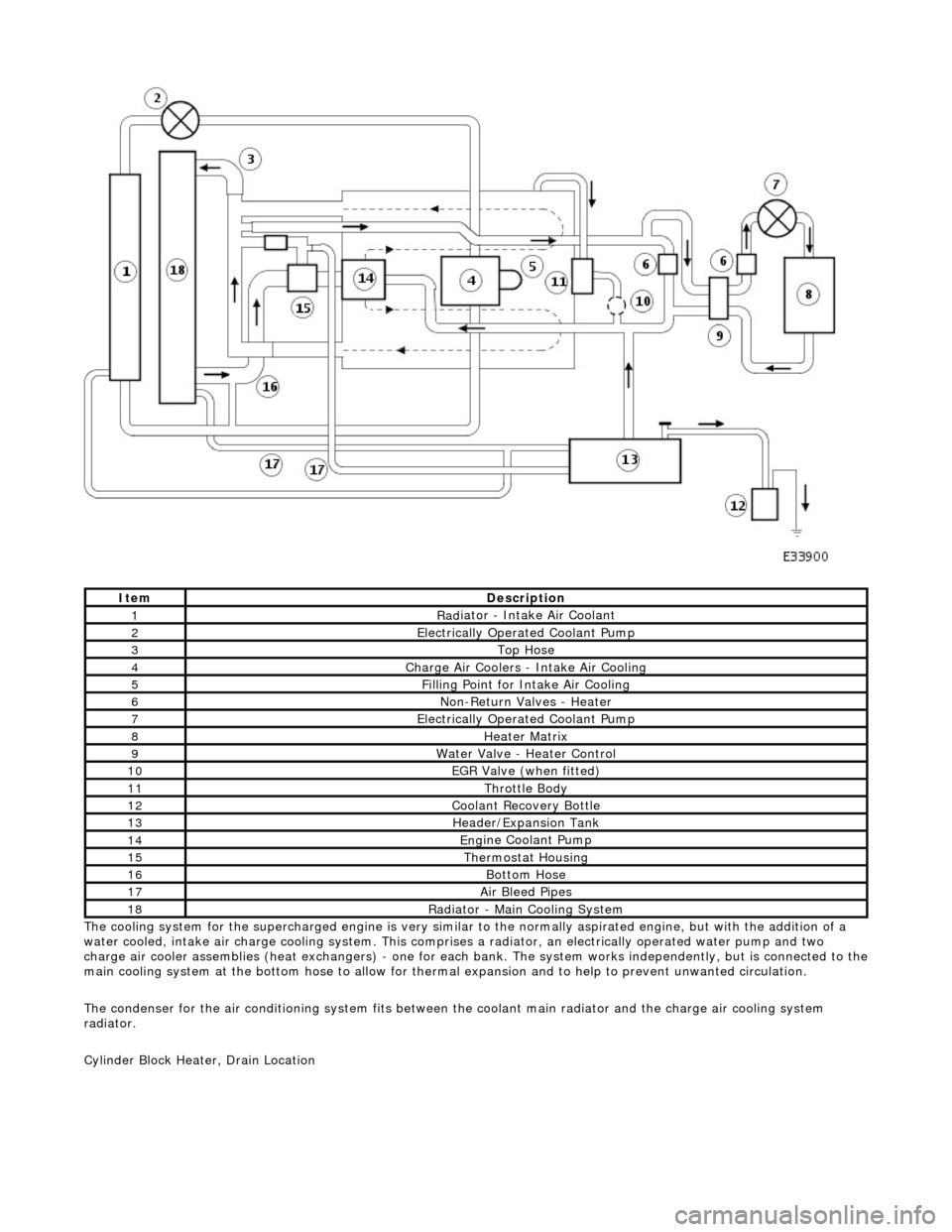
he cooling system for the supercharged engine is very similar
to the normally aspirated engine, but with the addition of a
water cooled, intake air charge cooling system. This comprises a radiator, an electrically operated water pump and two
charge air cooler assemblies (heat exchangers) - one for each bank. The system works independently, but is connected to the
main cooling system at the bottom hose to allow for therma l expansion and to help to prevent unwanted circulation.
The condenser for the air conditioning system fits between th e coolant main radiator and the charge air cooling system
radiator.
Cylinder Block Heater, Drain Location
ItemDe
scription
1Rad
iator - Intake Air Coolant
2Ele
ctrically Operated Coolant Pump
3Top Hose
4Charge Air Coo
lers -
Intake Air Cooling
5Fi
lling Point for Intake Air Cooling
6N
on-Return Valves - Heater
7Ele
ctrically Operated Coolant Pump
8Hea
ter Matrix
9Wate
r Valve - Heater Control
10EGR V
alve (when fitted)
11Thr
ottle Body
12Coolan
t Recovery Bottle
13H
eader/Expansion Tank
14Eng
ine Coolant Pump
15The
rmostat Housing
16Bottom
Hose
17Air Bleed
Pipes
18Rad
iator - Main Cooling System
Page 930 of 2490

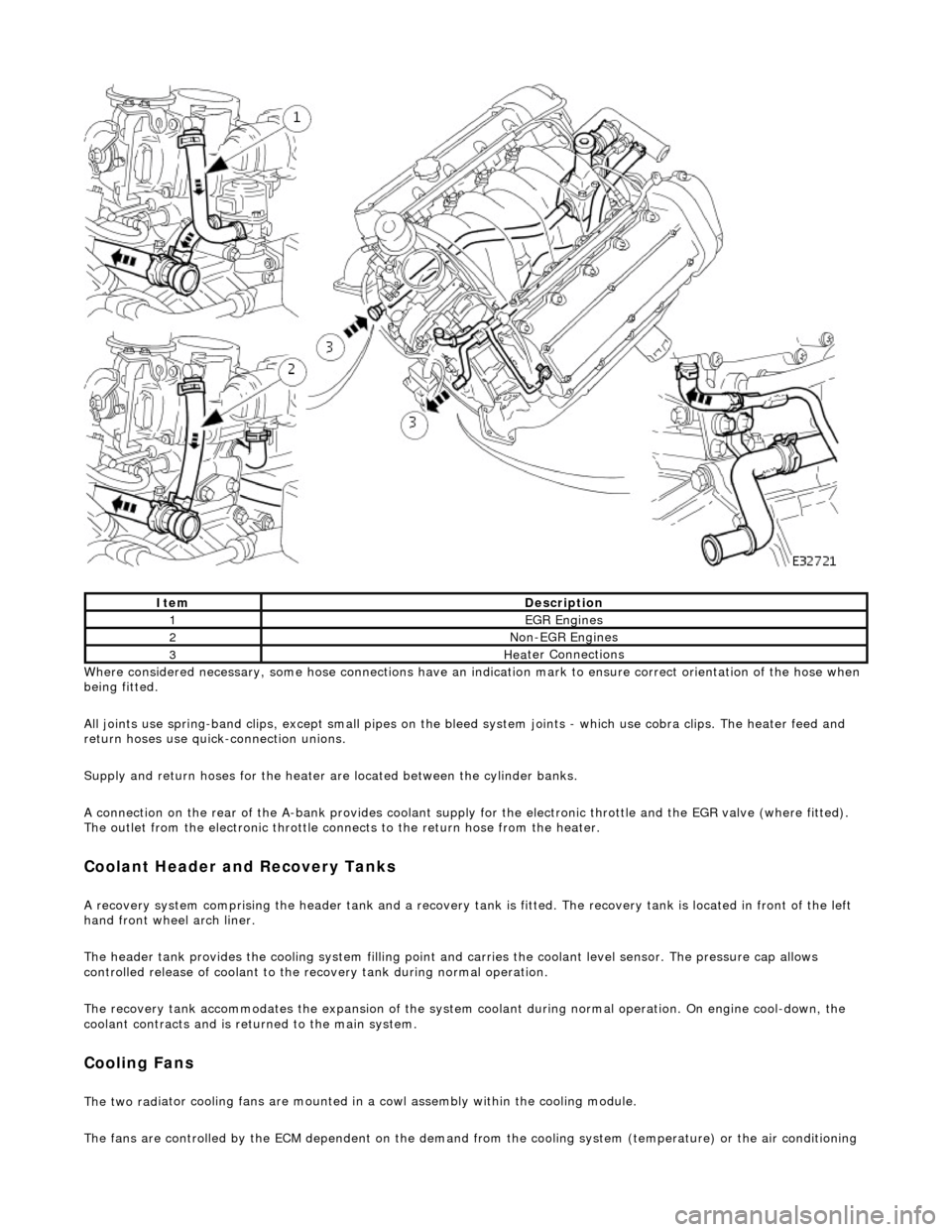
Whe r
e considered necessary, some hose conn
ections have an indication mark to ensure correct orientation of the hose when
being fitted.
All joints use spring-band clips, except small pipes on the bleed system joints - which use cobra clips. The heater feed and
return hoses use quick-connection unions.
Supply and return hoses for the heater are located between the cylinder banks.
A connection on the rear of the A-bank provides coolant supply for the electronic throttle and the EGR valve (where fitted).
The outlet from the electronic throttle connects to the return hose from the heater.
Cool
ant Header and Recovery Tanks
A recovery system comp
rising the header tank
and a recovery tank is fitted. The recove ry tank is located in front of the left
hand front wheel arch liner.
The header tank provides the cooling system filling point and carries the coolant level sensor. The pressure cap allows
controlled release of coolant to the re covery tank during normal operation.
The recovery tank accommodates the expansion of the system coolant during normal operation. On engine cool-down, the
coolant contracts and is returned to the main system.
Coo lin
g Fans
The two
rad
iator cooling fans are mounted in
a cowl assembly within the cooling module.
The fans are controlled by the ECM dependent on the demand fr om the cooling system (temperature) or the air conditioning
ItemDescrip
tion
1EGR
E
ngines
2Non
-
EGR Engines
3Hea
ter Connections
Page 963 of 2490

Engine Cooling - Coolant Expansi
on Tank
Re
moval and Installation
Remov
al
1.
O
pen the engine compartment and fit paintwork protection
sheets.
2. R
emove the centre trim panel
from the engine compartment.
1. Remove the left hand side enclosure panel.
2. Remove the centre trim panel.
3. Ensure that the cooling system is cool and very carefully,
remove the pressure cap.
4. Place a cloth under the expansion tank to absorb any spillage
caused by disconnecting the hoses.
5. R
elease the hoses (Quick Fit connections) from the expansion
tank.
1. Release the hose, expansion tank to thermostat housing (coolant outlet pipe on supercharged
engines).
2. Release the hose, expansion tank to recovery tank.
3. Release the hose, expansion tank to radiator..
6. Fit blanking plugs to the pipes and the tank.
7. Re
move the expansion tank from the mounting.
1. Disconnect the coolant level sensor connector.
2. Remove the nuts which secures the tank.
8. Remove the expansion tank from the vehicle.
1. Use a pipe clamp to clam p the bottom hose branch.
2. Release the pipe clip an d move it along the pipe.
3. Disconnect the tank from the bottom hose and