Intake Manifold Gaskets JAGUAR X308 1998 2.G Workshop Manual
[x] Cancel search | Manufacturer: JAGUAR, Model Year: 1998, Model line: X308, Model: JAGUAR X308 1998 2.GPages: 2490, PDF Size: 69.81 MB
Page 10 of 2490

В В В В В В В В В В В В В В В В В В В В
В В В В В В В В В В В В В В В В В В В В В В В В В В В В В В В В В В В В В В В В В В В В В В В В В В В В В В В В В В В В В В В В В В В В В В В В В В В В В В В В В В В В В В В В В В В В В В В В В В В В Flexplate
В VehiclesВ With
out:В
SuperchargerВ (12.53.13)В
В В В В В В В В В В В В В В В В В В В В Flexplate
В VehiclesВ With:В Supercharger В (12.53.13) В
В В В В В В В В В В В В В В В В В В В В Intake
В Camshaft В LH В (12.13.16) В
В В В В В В В В В В В В В В В В В В В В Intake
В Camshaft В RH В (12.13.14) В
В В В В В В В В В В В В В В В В В В В В Intake
В Manifo
ldВ (30.15.01) В
В В В В В В В В В В В В В В В В В В В В Intake
В Manifold В Gaskets В (30.15.08) В
В В В В В В В В В В В В В В В В В В В В Intake
В Manifold В LHВ (18.50.26) В
В В В В В В В В В В В В В В В В В В В В Intake
В Manifold В RH В (18.50.25) В
В В В В В В В В В В В В В В В В В В В В Intake
В Manifold В Gasket В LHВ (18.50.28) В
В В В В В В В В В В В В В В В В В В В В Intake
В Manifold В Gasket В RH В (18.50.27) В
В В В В В В В В В В В В В В В В В В В В Oil
В Pan В (12.60.44) В
В В В В В В В В В В В В В В В В В В В В Oil
В Pan В Gasket В (12.60.38) В
В В В В В В В В В В В В В В В В В В В В Oil
В PressureВ SwitchВ (88.25.07) В
В В В В В В В В В В В В В В В В В В В В Oil
В Pump В VehiclesВ Without:В SuperchargerВ (12.60.26)В
В В В В В В В В В В В В В В В В В В В В Oil
В Pump В VehiclesВ With:В Supercharger В (12.60.26) В
В В В В В В В В В В В В В В В В В В В В Primary
В Timing В Chain В LHВ 4.0L, В VehiclesВ Wit
hout: В SuperchargerВ (12.65.67)В
В В В В В В В В В В В В В В В В В В В В Primary
В Timing В Chain В LHВ 3.2L/4.0L,В VehiclesВ With: В Supercharger В (12.65.67) В
В В В В В В В В В В В В В В В В В В В В Primary
В Timing В Chain В RH В (12.65.66) В
В В В В В В В В В В В В В В В В В В В В Primary
В Timing В Chain В InnerВ Guide В LHВ (12.65.58) В
В В В В В В В В В В В В В В В В В В В В Primary
В Timing В Chain В InnerВ Guide В RH В (12.65.60) В
В В В В В В В В В В В В В В В В В В В В Primary
В Timing В Chain В Outer В Guide В LHВ (12.65.61) В
В В В В В В В В В В В В В В В В В В В В Primary
В TimingВ Chain В Outer В Gu
ide В RH В (12.65.57) В
В В В В В В В В В В В В В В В В В В В В Primary
В Timing В Chain В Tensioner В LHВ (12.65.55) В
В В В В В В В В В В В В В В В В В В В В Primary
В Timing В Chain В Tensioner В RH В (12.65.54) В
В В В В В В В В В В В В В В В В В В В В Secondary
В Timing В Chain В LH В (12.65.69) В
В В В В В В В В В В В В В В В В В В В В Secondary
В Timing В Chain В RH В (12.65.68) В
В В В В В В В В В В В В В В В В В В В В Secondary
В Timing В Chain В Tensioner В LHВ 4.0L,В VehiclesВ Without: В Supercharger В В
В В В В В В В В В (12.65.64)
В
В В В В В В В В В В В В В В В В В В В В Secondary
В Timing В Chain В Tensioner В LHВ 3.2L/4.0L, В VehiclesВ With:В SuperchargerВ В
В В В В В В В В В (12.65.64)
В
В В В В В В В В В В В В В В В В В В В В Secondar
yВ Timing В Chain В Tensioner В RH В 4.0L,В VehiclesВ Without: В Supercharger В В
В В В В В В В В В (12.65.63)
В
В В В В В В В В В В В В В В В В
В В В В В В В В В В В В В В В В В В В В В В В В В В В В В В В В В В В В В В В В В В В В В В В В В В В В В В В В
Secondar yВ Timing В Ch
ain
В Tensioner В RH В 3.2L/4.0L, В VehiclesВ With:В SuperchargerВ В
(12.65.63) В
Upper В Oil В Pan В 3.2L В (12.60.48) В
Upper В Oil В Pan В 4.0L, В VehiclesВ Without:В SuperchargerВ (12.60.48)В
Upper В Oil В Pan В 4.0L, В VehiclesВ With:В Supercharger В (12.60.48) В
Page 718 of 2490

Engine - Intake Manifold Gaskets
In-vehicle Repair
Removal
WARNING: BEFORE PROCEEDING, IT IS ESSENTIAL THAT THE WARNINGS GIVEN IN SECTION 100-00 (UNDER THE
HEADING 'SAFETY PRECAUTIONS') ARE READ AND UNDERSTOOD.
Special Tool(s)
Quick Fit Connector Release Tool
310-044
Quick Fit Connector Release Tool
310-054
Fuel Injection Pressu re Test Equipment
310-058
1. Open the engine compartment and fit paintwork protection
sheets.
2. Carefully remove the en gine covers, taking care not to damage
the plastic fixings or the rubber inserts.
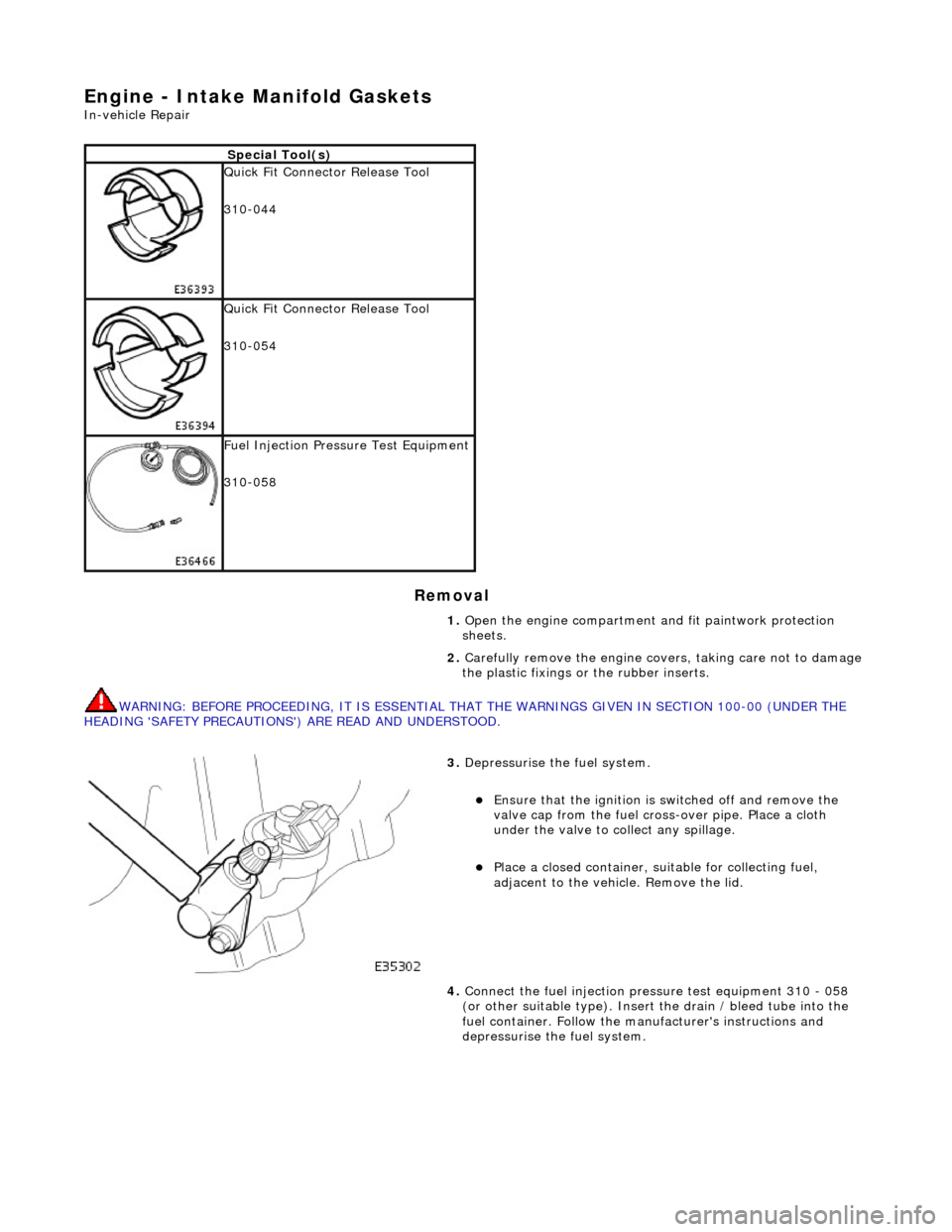
3. Depressurise the fuel system.
пЃ¬Ensure that the ignition is switched off and remove the
valve cap from the fuel cross-over pipe. Place a cloth
under the valve to collect any spillage.
пЃ¬Place a closed container, su itable for collecting fuel,
adjacent to the vehicle. Remove the lid.
4. Connect the fuel injection pres sure test equipment 310 - 058
(or other suitable type). Insert the drain / bleed tube into the
fuel container. Follow the ma nufacturer's instructions and
depressurise the fuel system.
Page 1111 of 2490

the
intake elbow provide connections for vacuum actuators and are also used to redirect emissions into the engine.
On the right-hand side of the elbow a la rge diameter pipe connects to the brake servo. The smaller pipe provides a vacuum
feed to the fuel rail pressure regulator and throttle cruise control system. On the le ft-hand side of the elbow the front pipe
supplies vacuum control for the evaporative emissions system valves.
Emissions from the engine part load breather (bank 2) and pu rged fuel vapor from the EVAP valve are drawn via a common
T piece into the left-hand side of the intake elbow. Re-cir culated exhaust gas enters the intake elbow via the EGR valve
which is mounted directly on the rear of the elbow : where the EGR system is not used, a blanking plate is fitted.
The fuel system, throttle and emission control system s are described more fully in the relevant sections.
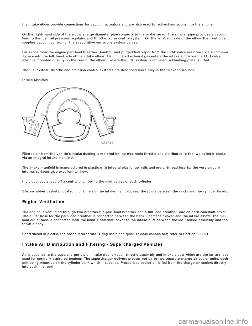
Intake Manifold
Filtered air from the vehicle's intake ducting is metered by th e electronic throttle and distributed to the two cylinder banks
via an integral intake manifold.
The intake manifold is manufactured in plastic with integral plastic fuel rails and metal-thread inserts; the very smooth
internal surfaces give excellent air flow.
Individual ducts lead off a central chamber to the inlet valves of each cylinder.
Silicon-rubber gaskets, loca ted in channels in the intake manifold, seal th e joints between the ducts and the cylinder heads.
Engine Ventilation
The e
ngine is ventilated through two brea
thers; a part-load breather and a full-load breather, one on each camshaft cover.
The outlet hose for the part-load breather is connected between the bank 2 camshaft cover and the intake elbow. The full-
load outlet hose is connected from the bank 1 camshaft cover to the intake duct between the MAF sensor assembly and the
throttle body.
Constructed in plastic, the hoses incorporate O-ring seal s and quick-release connectors; refer to Section 303-01.
I
ntake Air Distribution and Filtering - Supercharged Vehicles
Ai
r is supplied to the supercharger via an
intake cleaner/duct, throttle assembly and intake elbow which are similar to those
used for normally aspirated engines. The su percharger delivers pressurized air to two separate charge air cooler units, each
unit being mounted on the cy linder bank which it supplies. Pr essurized cooled air is fed from the charge air coolers directly
into each inlet port.