oil filter JAGUAR X308 1998 2.G Workshop Manual
[x] Cancel search | Manufacturer: JAGUAR, Model Year: 1998, Model line: X308, Model: JAGUAR X308 1998 2.GPages: 2490, PDF Size: 69.81 MB
Page 14 of 2490

303‐07: En gine Ignition
Specification
Diagnosis and Testing
Engine Ignition
Diagnosis and Testing
Engine Ignition
Inspection and Verification
Driver Information Chart
Default mode Definitions
Diagnostic Trouble Code (DTC) index
Pinpoint Tests
Removal and Installation
Ignition Coil ‐On ‐Plug LH (18.20.44)
Ignition Coil ‐On ‐Plug RH (18.20.43)
Ignition Module (18.20.30)
Spark Plugs (18.20.02)
303‐08: En
gine Emission Control
Specification
Diagnosis and Testing
Engine Emission Control
Inspection and Verification
Diagnostic Trouble Code (DTC) Index
Pinpoint Tests
Removal and Installation
Exhaust Gas Recirculation (EGR) Valve (17.45.01)
Exhaust Manifold to Exhaust Gas Recirculation (E
GR) Valve Tube (17.45.11)
303‐12: Intake Air Distribution and Filtering
Removal and Installation
Air Cleaner (19.10.05)
Air Cleaner Element (19.10.08)
Charge Air Cooler LH (18.50.19)
Charge Air Cooler RH (18.50.18)
Charge Air Cooler Gasket LH (18.50.22)
Charge Air Cooler Gasket RH (18.50.21)
Supercharger (18.50.
15)
Page 16 of 2490

Knock Sensor (KS) RH (18.30.93)
Variable Camshaft Timing (VCT) Oil Co ntrol
Solenoid (18.30.90)
307: Automatic Transmission/Transaxle
307‐01A : Automatic Transmission/Transaxle ‐ 3.2L NA V8 ‐ AJ26/4.0L NA V8 ‐ AJ27
Specification
Description and Operation
Transmission Description
Diagnosis and Testing
Diagnostic Strategy
General Procedures
Transmission Fluid Drain and Refill (44.24.02)
In‐Ve
hicle Repair
Electronic Pressure Control (EPC) Solenoid (44.15.51)
Extension Housing Seal (44.20.18)
Extension Housing O ‐Ring Seal (44.20.19)
Main Control Valve Body (44.40.01)
Output Shaft Speed (OSS) Sensor (44.15.41)
Shift Solenoids (SS) (44.15.50)
Transmission Control Module (TCM) (44.15.32)
Transmission Fluid Filter (44.24.07)
Transmission Fl
uid Pan (44.24.04)
Transmission Fluid Pan Gasket (44.24.05)
Transmission Internal Wiring Harness (44.15.35)
Transmission Internal Wiring Harness Electrical Connector O‐Ring Seals
(44.24.20)
Transmission Range (TR) Sensor
Transmission Support Insulator (12.45.04)
Turbine Shaft Speed (TSS) Sensor (44.15.40)
Removal
Transmission (44.20.01)
Disassembly and Assembly of Subassemblies
Input Sh
aft Seal (44.32.07)
Torque Converter (44.17.07)
Installation
Transmission (44.20.01)
Mass
Airflow
Sen s
or
Knock
Sensor
(KS)
LH
(18.30.92)
Page 20 of 2490

310‐01: Fu el Tank and Lines
Removal and Installation
Fuel Level Sensor (88.25.32)
Fuel Pump (19.45.08)
Fuel Tank (19.55.01)
310‐02
:
Acceleration Control
General Procedures
Accelerator Cable Adjustment (12.20.05)
Removal and Installation
Accelerator Cable (19.20.06)
310‐03: Speed Control
Diagnosis and Testing
Speed Con
trol
4: Electrical
412: Climate Control System
412‐00: Climate Control System ‐ General Information
Specification
Description and Operation
Climate Control System
Diagnosis and Testing
Climate Control System
General Procedures
Air Conditioning (A/C) System Check ‐ Retail Procedure
Air Conditioning (A/C) System Recovery, Evacuation and Charging (82.30.30)
Contaminated Refrigerant Ha
ndling
Manifold Gauge Set Connection
Refrigerant Adding (82.30.02)
Refrigerant Oil Adding
Refrigerant System Tests
412‐01: Air Distribution and Filtering
Description and Operation
Page 522 of 2490

diverter val
ve (if fitted) and oil filter.
Main
bearings
which are grooved in the upper positions and plain in
the lower positions. They are manufactured from
aluminium / tin material.
A c
rankshaft with under
cuts and rolled fillets for extra strength.
Fracture
-split connecting rods in sintered-forged steel.
Brackets
bolted to the front of
the cylinder
block are used to mo unt all accessories.
A sin
gle, seven ribbed vee belt
drives the accessories.
An au
tomatic belt tensioner for the front accessory drive,
incorporating a wear indicator.
An advanced en
gine management system inco
rporating electronic throttle control.
The un
it meets the requirements of the CARB OBDII USA legislation.
Ancillary Systems
The an
ci
llary systems, driven by the engine, each have a
detailed Description and Operation along with Diagnostic
Procedures, and Removal and Installation instructions ; refer to the following sections of this manual:
Power Steeri
ng Pump - Section 211-02
Ai
r Conditioning Compressor - Sectio
n 412-03
Engine
C
ooling Pump - Section 303-03
Generator
- Sectio
n 414-02
The drive belt, idler pulley and automatic tensioner are described in Section 303-05.
The engine starting system is described in Section 303-06.
En
gine Management and Emission Control System
Engine Control Modu
le (ECM)
Engine
management and exhaust emissions are controlled by the ECM, which has the
following main functions:
Fu
el injection
Idle
s
peed
Ignition Ev
aporative loss system
Engine
cooling fans Clim
ate control compressor clutch demand
The microprocessor within the ECM receiv es signals from various sensors and other modules and uses a pre-determined
program to compute engine management functions.
Adaptive functions are incorporated in the ECM to cater for co ntinuous adjustments to its computations to suit prevailing
conditions. Because the system also controls emissions to suit all modes, neither CO levels nor idle speed require service
attention or adjustment, except if an error should occur.
On Board Diagnostics are controlled by the ECM with the continuous monitoring of incoming signals and the subsequent
verification against what the module expects to 'see'. Should a si gnal be incorrect or missing, the ECM will substitute a fixed
value to provide the 'limp home mode' and alert the driver of the problem. Fixed values may be adopted for:
Transmission oil
temperature
Mechanica
l
guar
d position
Throttle blade angle Camshaft position
Inta
k
e air temperature
Diagnostic trouble codes (DTC), including OBD II codes, are stored in the ECM memo ry and can be read by an appropriate
retrieval tool.
Should either the ECM or TCM fa il, ensure that the control housing cooling fan is operating correctly. Failure of the cooling
fan MUST be rectified before renewing a control module and details of a fa n failure should accompany a returned control
module.
Page 555 of 2490

I
nstallation
Tigh
ten each bolt to 8 to 12 Nm initial torque value.
Ti
ghten to a final torque of 57 to 63 Nm.
27. Check that the cranks haft turns freely.
28. Repeat the previous operations for each connecting rod
bearing as necessary.
1. Install the oil pan bo dy assembly. Refer to Operation 12.60.48.
2. Po
sition and align the oil pan gasket to the oil pan body
assembly.
Inse
rt the seal into the locating positions in the groove,
working around from a corner.
Press in the remai
nder of th
e seal, following the same
procedure.
3. Install th
e oil pan to the oil pan body.
1. Position and align the oil pan.
2. Install, but do not tighte n, all eighteen bolts which
secure the oil pan.
4. Tigh
ten the bolts to the correct
torque figure 11-13 Nm, in the
sequence indicated.
Tigh
ten the drain plug to 30-40 Nm.
Install a new oil
filter.
Page 753 of 2490

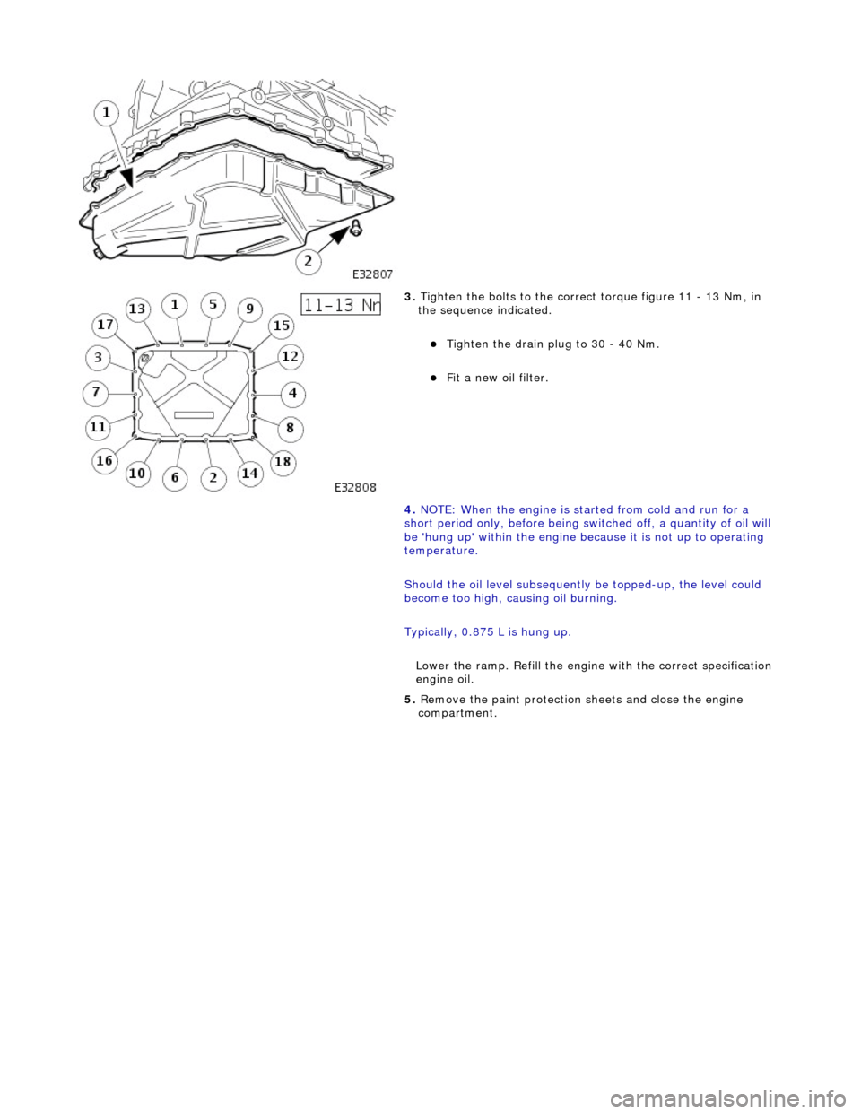
3. Tighten the bolts to the correct torque figure 11 - 13 Nm, in
the sequence indicated.
Tighten the drain plug to 30 - 40 Nm.
Fit a new oil filter.
4. NOTE: When the engine is star ted from cold and run for a
short period only, before being swit ched off, a quantity of oil will
be 'hung up' within the engine because it is not up to operating
temperature.
Should the oil level subsequently be topped-up, the level could
become too high, causing oil burning.
Typically, 0.875 L is hung up.
Lower the ramp. Refill the engine with the correct specification
engine oil.
5. Remove the paint protection sheets and close the engine
compartment.
Page 754 of 2490

Engine - Oil Pressure Switch
In-vehicle Repair
Removal
Installation
1.
Raise vehicle on four post ramp.
2. Remove oil pressure switch.
Disconnect connector.
Remove oil pressure switch from oil filter head.
1. NOTE: Fit new sealing washer to oil pressure switch.
Installation is reverse of removal.
Page 830 of 2490

Engine - Upper Oil Pan3.2L NA V8 - AJ26
In-vehicle Repair
Removal
Special Tool(s)
Installer/remover, Oil Filter
303-752
1. Disconnect the batt ery ground cable.
Remove the battery cover.
2. Open the engine compartment and fit paintwork protection
sheets.
3. Set the engine compartment cover to the service access
position.
4. Remove the timing cover and al l associated components, as
detailed in Operation 12.65.01.
5. Remove both front wheel and tyre assemblies. Refer to
Operation 74.20.05.
6. Remove the undertray. Re fer to Operation 76.22.90.
7. Remove the two bolts which secu re the generator cooling duct
to the oil pan body and remove the duct.
8. Remove the front cross member for access. Refer to Operation
76.10.05.
9. Drain the engine oil.
1. Position the waste oil bowser.
2. Remove the drain plug from the oil pan and drain the engine oil.
Fit a new sealing washer to the drain plug.
Page 831 of 2490

Wipe the drain plug and install it to the oil pan to prevent
oil dripping.
Move the oil bowser away from the vehicle.
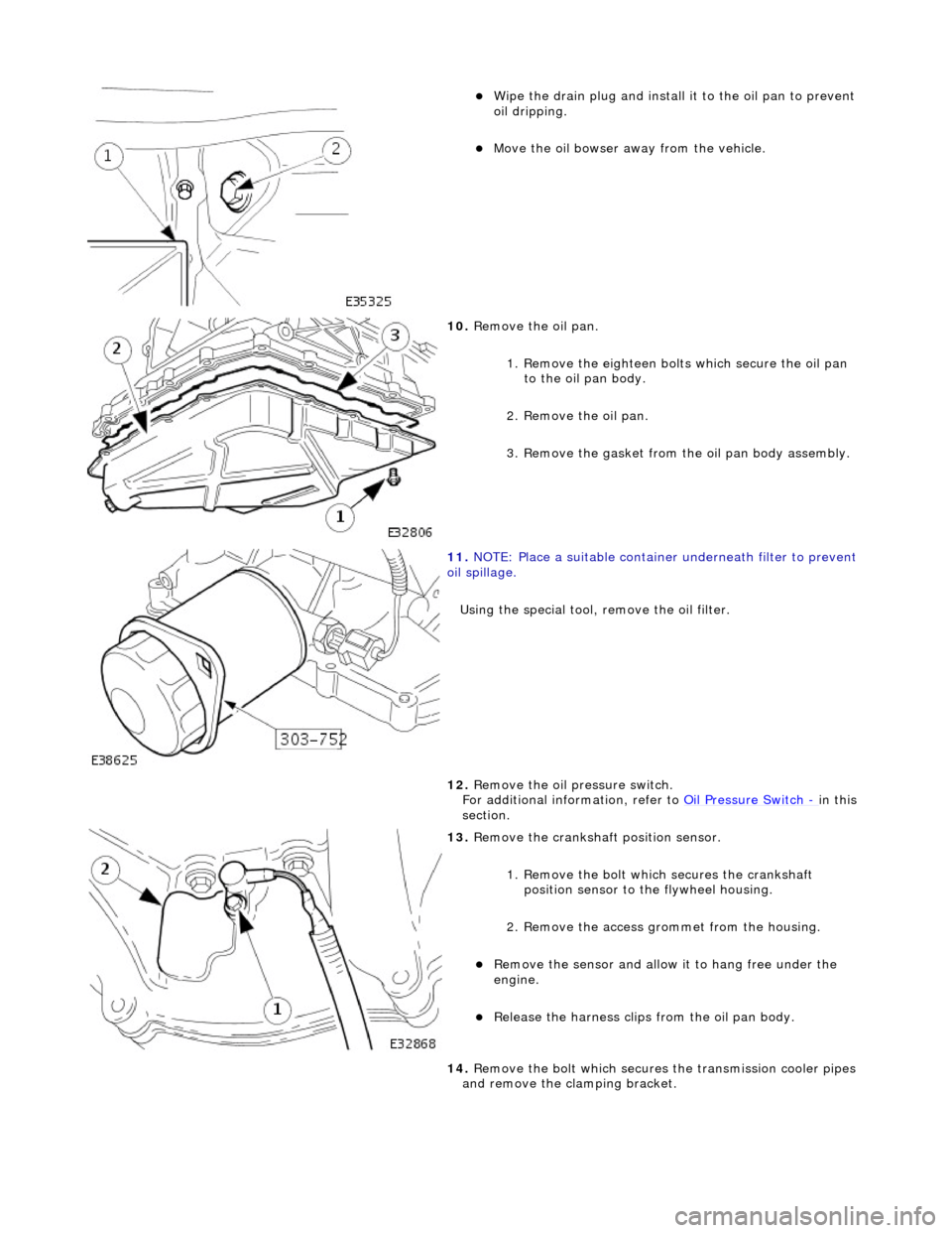
10. Remove the oil pan.
1. Remove the eighteen bolt s which secure the oil pan
to the oil pan body.
2. Remove the oil pan.
3. Remove the gasket from the oil pan body assembly.
11. NOTE: Place a suitable container underneath filter to prevent
oil spillage.
Using the special tool, remove the oil filter.
12. Remove the oil pressure switch.
For additional information, refer to Oil Pressure Switch
- in this
section.
13. Remove the crankshaft position sensor.
1. Remove the bolt which secures the crankshaft position sensor to the flywheel housing.
2. Remove the access grommet from the housing.
Remove the sensor and allow it to hang free under the
engine.
Release the harness clips from the oil pan body.
14. Remove the bolt which secures the transmission cooler pipes
and remove the clamping bracket.
Page 833 of 2490

Installation
19. Remove the eight screws an d release the windage tray.
20. Remove the oil filter adaptor.
21. Clean all components and releva nt mating faces; cylinder
block, oil pan, oil pan body, wi ndage tray, oil pick-up pipe and
timing cover.
1. Reposition the windage tray and install the eight screws,