check transmission fluid JAGUAR X308 1998 2.G Workshop Manual
[x] Cancel search | Manufacturer: JAGUAR, Model Year: 1998, Model line: X308, Model: JAGUAR X308 1998 2.GPages: 2490, PDF Size: 69.81 MB
Page 47 of 2490
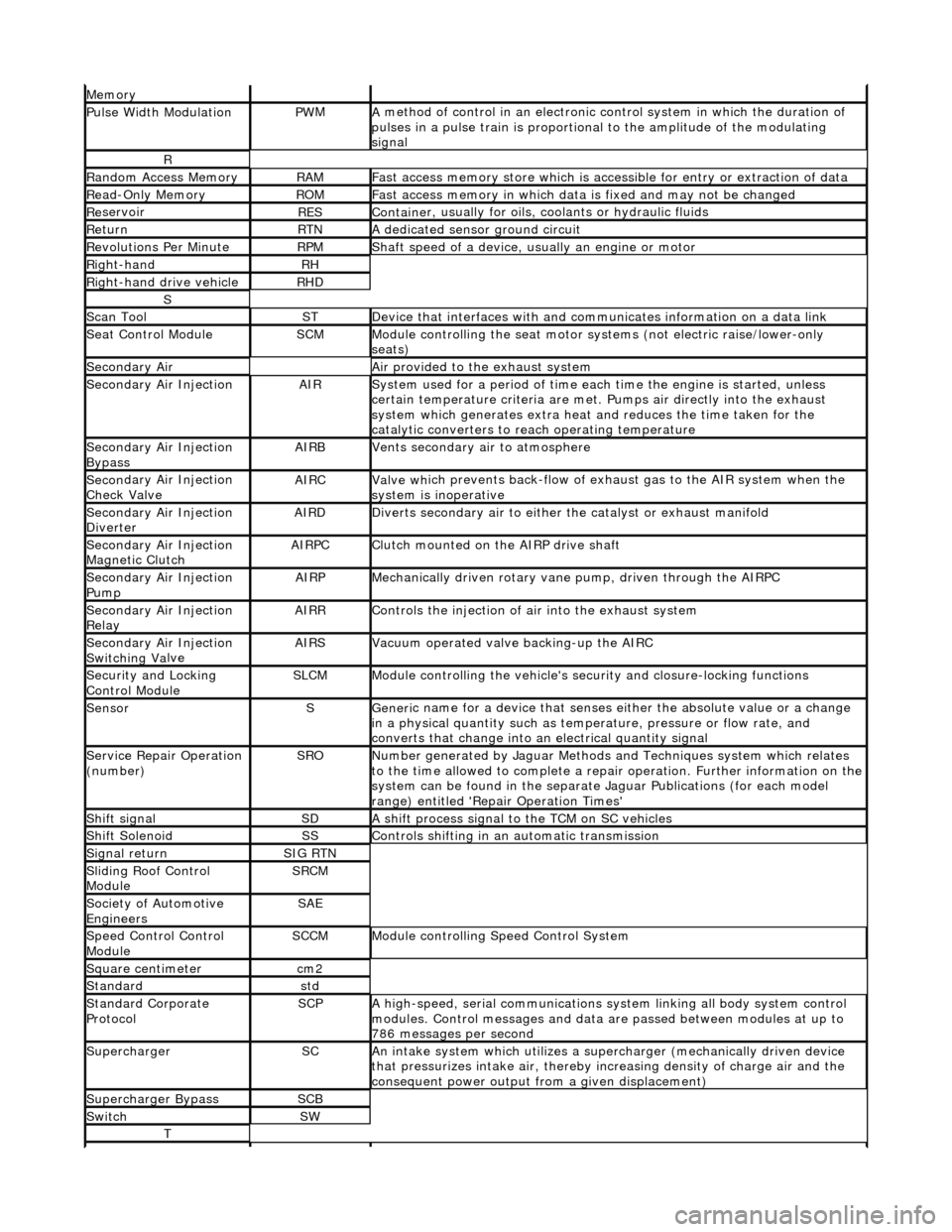
Mem
ory
Pulse Width ModulationPW
M
A
method of control in an electronic co
ntrol system in which the duration of
pulses in a pulse train is proportional to the amplitude of the modulating
signal
R
Ran
dom Access Memory
RAMF
ast access memory store which is accessible for entry or extraction of data
Re
ad-Only Memory
RO
M
F
ast access memory in which data
is fixed and may not be changed
Re
servoir
RESContaine
r, usually for oils,
coolants or hydraulic fluids
Re
turn
RTNA
dedicated sensor ground circuit
R
evolutions Per Minute
RP
M
Shaft speed o
f a device, us
ually an engine or motor
R
ight-hand
RH
Right-hand drive veh
icle
RHD
S
Scan T
ool
STDe
vice that interfaces with and comm
unicates information on a data link
Se
at Control Module
SCMModule
controlling the seat motor systems (not electric raise/lower-only
seats)
Secon
dary Air
Air pro
vided to the exhaust system
Secon
dary Air Injection
AIRSy
stem used for a period of time each
time the engine is started, unless
certain temperature criter ia are met. Pumps air directly into the exhaust
system which generates extra heat and reduces the time taken for the
catalytic converters to reach operating temperature
Secon
dary Air Injection
Bypass
AIRBVents secon
dary air to atmosphere
Secon
dary Air Injection
Check Valve
AIRCValve wh
ich prevents back-flow of exhaust gas to the AIR system when the
system is inoperative
Secon
dary Air Injection
Diverter
AIRDD
iverts secondary air to either
the catalyst or exhaust manifold
Secon
dary Air Injection
Magnetic Clutch
AIRP
C
Clu
tch mounted on the AIRP drive shaft
Secon
dary Air Injection
Pump
AIRPMe
chanically driven rotary vane
pump, driven through the AIRPC
Secon
dary Air Injection
Relay
AIRRCont
rols the injection of air into the exhaust system
Secon
dary Air Injection
Switchin
g Va
lve
AIRSV
acuum operated valve backing-up the AIRC
Secu
rity and Locking
Control Module
SLCMModul
e controlling the vehicle's security and closure-locking functions
SensorSGeneri
c name for a device
that senses either the absolute value or a change
in a physical quantity su ch as temperature, pressure or flow rate, and
converts that change into an electrical quantity signal
Servic
e Repair Operation
(number)
SRONu
mber generated by Jaguar Methods
and Techniques system which relates
to the time allowed to complete a repair operation. Further information on the
system can be found in the separate Jaguar Publications (for each model
range) entitled 'Repair Operation Times'
Shif
t signal
SDA
shift process signal to the TCM on SC vehicles
Shif
t Solenoid
SSControls shi
fting in an automatic transmission
Si
gnal return
SIG RTN
Slidin
g Roof Control
Module
SRCM
Society of Automotive
Engineers
SAE
Speed
Control Control
Module
SCCMModule con
trolling Speed Control System
Square c
entimeter
cm
2
Stan
dard
std
Stan
dard Corporate
Protocol
SCPA
high-speed, serial communications system linking all body system control
modules. Control messages and data ar e passed between modules at up to
786 messages per second
SuperchargerSCAn in
take system which utilizes a supercharger (mechanically driven device
that pressurizes intake air, thereby in creasing density of charge air and the
consequent power output from a given displacement)
Supercharger
Bypass
SCB
SwitchSW
T
Page 318 of 2490
Comp
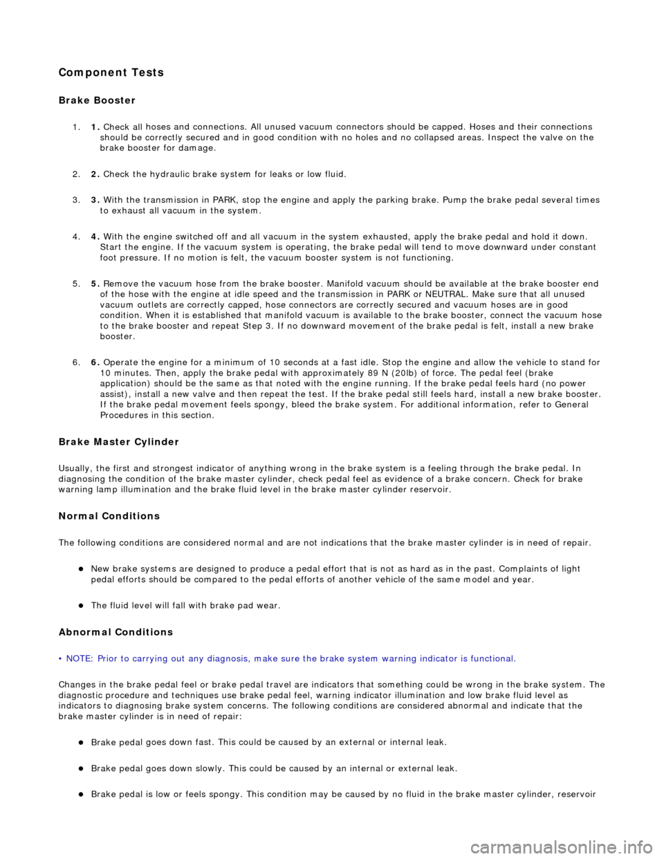
onent Tests
Bra
k
e Booster
1.
1. Chec k all
hoses and connections. All unused vacuum connectors should be capped. Hoses and their connections
should be correctly secured and in good condition with no holes and no collapsed areas. Inspect the valve on the
brake booster for damage.
2. 2. Check the hydraulic brake system for leaks or low fluid.
3. 3. With the transmission in PARK, stop the engine and apply the parking brake. Pump the brake pedal several times
to exhaust all vacuum in the system.
4. 4. With the engine switched off and all vacuum in the system exhausted, appl y the brake pedal and hold it down.
Start the engine. If the vacuum system is operating, the brake pedal will tend to move downward under constant
foot pressure. If no motion is felt, the vacuum booster system is not functioning.
5. 5. Remove the vacuum hose from the brake booster. Manifold vacuum should be available at the brake booster end
of the hose with the engine at idle speed and the transm ission in PARK or NEUTRAL. Make sure that all unused
vacuum outlets are correctly capped, hose connectors are correctly secured and vacuum hoses are in good
condition. When it is established that manifold vacuum is available to the brake booster, connect the vacuum hose
to the brake booster and repeat Step 3. If no downward movement of the brake pedal is felt, install a new brake
booster.
6. 6. Operate the engine for a minimum of 10 seconds at a fast idle. Stop the engine and allow the vehicle to stand for
10 minutes. Then, apply th e brake pedal with approximately 89 N ( 20lb) of force. The pedal feel (brake
application) should be the same as that noted with the engine running. If the brake pedal feels hard (no power
assist), install a new valve and then re peat the test. If the brake pedal still feels hard, in stall a new brake booster.
If the brake pedal movement feels spongy, bleed the brak e system. For additional information, refer to General
Procedures in this section.
Bra k
e Master Cylinder
Usual
l
y, the first and strongest
indicator of anything wrong in the brake syst em is a feeling through the brake pedal. In
diagnosing the condition of the brake master cylinder, check pedal feel as evidence of a brake concern. Check for brake
warning lamp illumination and the brake fluid le vel in the brake master cylinder reservoir.
Normal Conditio
ns
The fo
llowing conditions are considered norm
al and are not indications that the brake master cylinder is in need of repair.
New bra
ke systems are designed to produc
e a pedal effort that is not as hard as in the past. Complaints of light
pedal efforts should be compared to the pedal effort s of another vehicle of the same model and year.
The fl
uid level will fall with brake pad wear.
Abnormal Conditions
•
NOTE: Prior to carrying out any diag
nosis, make sure the brake system warning indicator is functional.
Changes in the brake pedal feel or brake pedal travel are in dicators that something could be wrong in the brake system. The
diagnostic procedure and techniques use brake pedal feel, warning indicator illu mination and low brake fluid level as
indicators to diagnosing brake system co ncerns. The following conditions are cons idered abnormal and indicate that the
brake master cylinder is in need of repair:
Brake ped a
l goes down fast. Th
is could be caused by an ex ternal or internal leak.
Brake pedal goes down slowly
. This could be
caused by an internal or external leak.
Brak
e pedal is low or feels spongy. This condition may be ca
used by no fluid in the brake master cylinder, reservoir
Page 978 of 2490
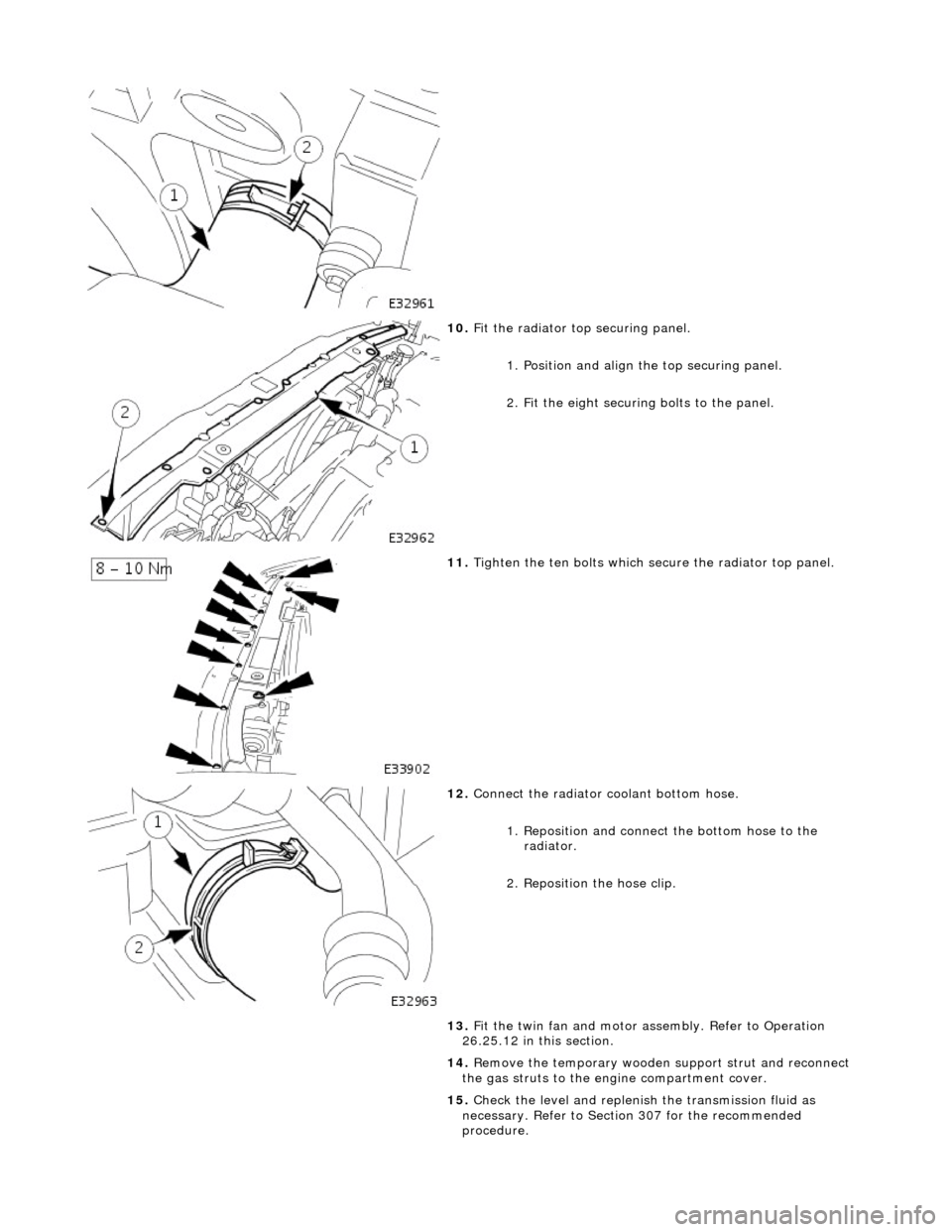
10. F
it the radiator top securing panel.
1. Position and align th e top securing panel.
2. Fit the eight securing bolts to the panel.
11. Tigh
ten the ten bolts which secu
re the radiator top panel.
12. Connect
the radiator coolant bottom hose.
1. Reposition and connect the bottom hose to the radiator.
2. Reposition the hose clip.
13. Fit the twin fan and motor assembly. Refer to Operation
26.25.12 in this section.
14. Remove the temporary wooden support strut and reconnect
the gas struts to the engine compartment cover.
15. Check the level and replenish the transmission fluid as
necessary. Refer to Section 307 for the recommended
procedure.
Page 985 of 2490
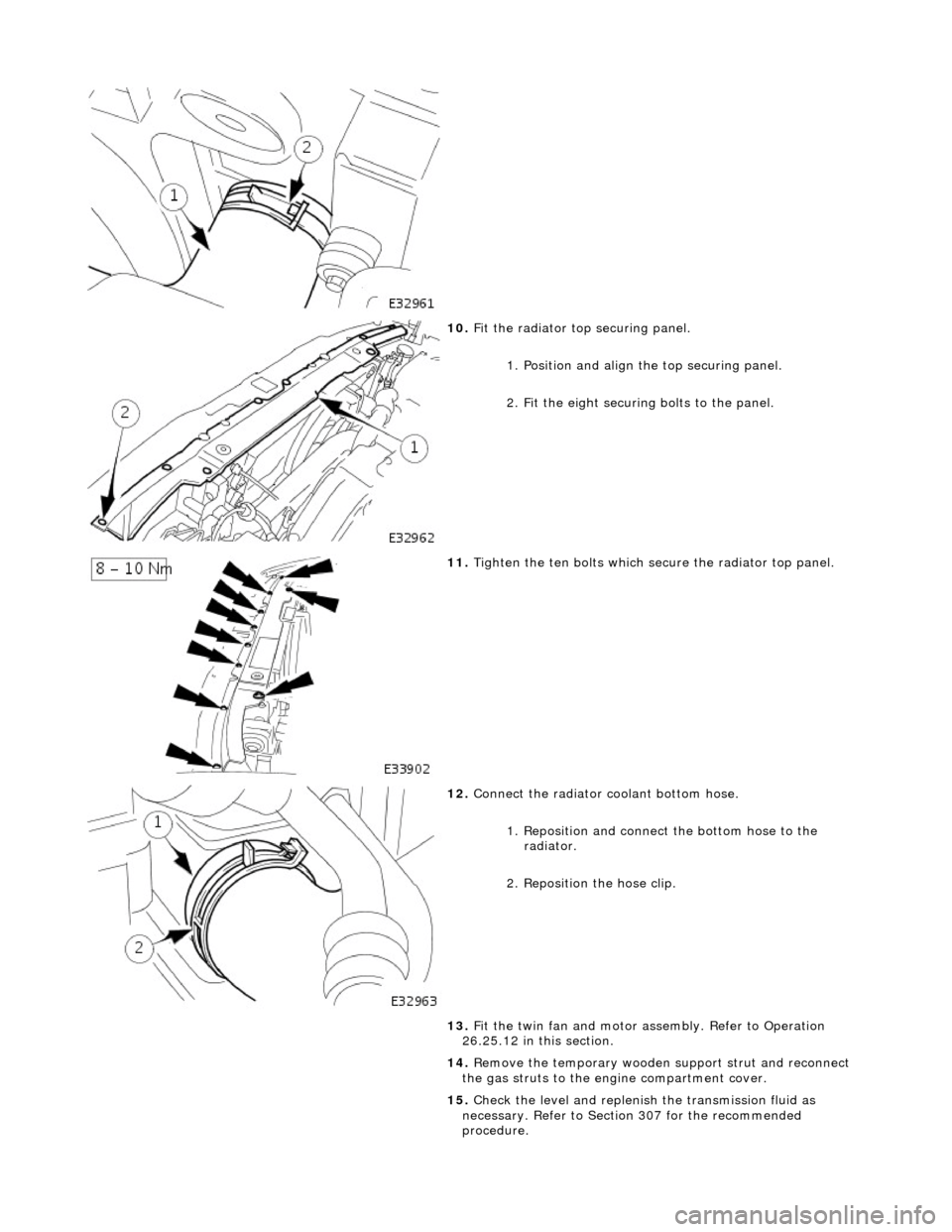
10
.
Fit the radiator top securing panel.
1. Position and align th e top securing panel.
2. Fit the eight securing bolts to the panel.
11
.
Tighten the ten bolts which secu re the radiator top panel.
12
.
Connect the radiator coolant bottom hose.
1. Reposition and connect the bottom hose to the radiator.
2. Reposition the hose clip.
13. Fit the twin fan and motor assembly. Refer to Operation
26.25.12 in this section.
14. Remove the temporary wooden support strut and reconnect
the gas struts to the engine compartment cover.
15. Check the level and replenish the transmission fluid as
necessary. Refer to Section 307 for the recommended
procedure.
Page 1262 of 2490
Contains th
e hydraulic system pump.
Contains
th
e fluid temperature sensor.
The epicyclic geartrain:
Provi des fi
ve forward gears and Reverse.
Has
h
ydraulically actuated, multi-disk clutches, to select the required gear ratios.
Feature
s clutch-to-clutch operation to permit
gear shifts for uninterrupted power flow.
The electro-hydraulic control unit:
Is lo c
ated in the lower part of
the unit, within the fluid pan.
Is controlled
by the TCM (transmissio
n control module), and the manual selector valve which is cable operated.
Re
gulates the flow of fluid to the ge
artrain clutches via three solenoid-operated valv es and the manual selector
valve.
Has fi ve pressure
regulators for controll
ing fluid pressures within the system.
Is con
nected to the TCM via a 16-way connector mounted on
the left-hand side of the transmission casing. Refer to
Connector Pins Identification, Section 307-01A.
The hydraulic system pump:
Is l o
cated at the front of the transmission casing.
Is dri
v
en from the impeller hub,
pressurising the fluid whenever the engine is running.
Supplie
s fluid under pressure to the torq
ue converter, geartrain, electro-hydr aulic control unit and the lubrication
circuit.
D r
aws fluid from the fluid pa
n below the transmission casing, through a filter.
The rear extension housing:
Is bolt
ed to the rear of the transmission casing.
Provides the rear engine / transmi
ssion mo
unting point; refer to section 303-01.
Carrie
s the transmission output shaft oil seal.
Filled-for-l
i
fe Fluid System
The
transm
ission is 'filled for life' and
does not require fluid changes, except where extreme driving conditions prevail.
Routine level checking is not required and a dipstick is not pr ovided. A level / filler plug is fitted for level checking and
replenishment, following service actions; see 303-01 General Procedures.
Transmission Torque Converter
Page 1268 of 2490
Input speed is monitored by the TCM with a rationality check being made against output speed. A fault will be flagged if the
indicated input speed exceeds 7400 rpm. Additionally, a failure judgement will be made if the indicated input speed is <160
rpm with engine speed >608 rpm and output speed >224 rpm
The procedure is similar for the output sp eed diagnostic. A fault (non OBDII) will be flagged if the indicated input speed
exceeds 6712 rpm. Additionally a failure judgement will be ma de if the indicated output speed is <160 rpm and the average
road wheel speed exceeds 100 rpm.
Under normal circumstance s after the output speed diagnost ic fault code has been set, the TCM uses rear wheel speed
information to compute its calculations, this has no effect on transmission operation. However, should a second fault occur,
in the ABS system, thus making rear wheel speed information unavailable, an additional fault code will be logged.
Control Systems
Introduction
Gear selection is achieved by controlling the flow of transmission fluid to internal multi-disc clutches.
The three solenoid valves direct the transmission fluid flow to the selected clutches and the pressure regulators control the
fluid pressure to each component. One pr essure regulator serves as a master pressure control for the entire system and a
second is used exclusively for torque converter clutch lock-up operation.
The TCM controls the internal components thus determining gear selection and shift pattern.
In the event of an electronic system fault the basic function s Park, Reverse Neutral and Drive Fourth are retained by the
hydraulic system.
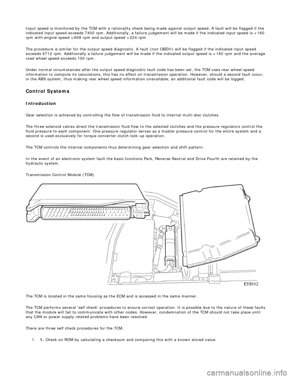
Transmission Control Module (TCM)
The TCM is located in the same housing as th e ECM and is accessed in the same manner.
The TCM performs several 'self check' procedur es to ensure correct operation. It is possible due to the nature of these faults
that the module will fail to communicate with other nodes. However, condemnation of the TCM should not take place until
any CAN or power supply related problems have been resolved.
There are three self check procedures for the TCM. 1. 1. Check on ROM by calculatin
g a checksum and comparing this with a known stored value.
Page 1278 of 2490
Pinpoint test A: P0741, P0742, P0743
Pinpoint test B: P0743
Connector pin(s) bent or tracking between
connections
*
DTC P1789 Ignition supply malfunction >7 < 9
voltsBattery charging system fault
Blown fuse
Harness fault
Connector loose or corroded
Connector pin(s) bent or tracking between
connections Ground fault
*
*
*
*
*
*GO to Pinpoint
Test K
*
DTC P0710 Transmission fluid temperature
sensor malfunctionDamaged sensor
Sensor out of range / short
Harness open circuit
Harness short
Connector loose or corroded
*
*
*
*
*GO to Pinpoint
Test L
*
PINPOINT TEST A : P0741, P0742, P0743
TEST CONDITIONSDETAILS/RESULTS/ACTIONS
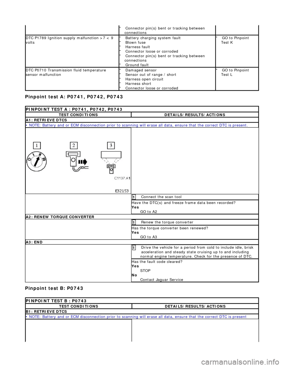
A1: RETRIEVE DTCS
• NOTE: Battery and or ECM disconnection prior to scanning wi
ll erase all data, ensure that the correct DTC is present.
Connect the scan tool 1
Have the DTC(s) and freeze frame data been recorded?
Yes GO to A2
A2: RENEW TORQUE CONVERTER
Renew the torque converter 1
Has the torque converter been renewed?
Yes GO to A3
A3: END
Drive the vehicle for a period from cold to include idle, brisk
acceleration and steady state cruising up to and including
normal engine temperature. Check for the presence of DTC. 1
Has the fault code cleared?
Yes STOP
No Contact Jaguar Service
PINPOINT TEST B : P0743
TEST CONDITIONSDETAILS/RESULTS/ACTIONS
B1: RETRIEVE DTCS
• NOTE: Battery and or ECM disconnection prior to scanning wi ll erase all data, ensure that the correct DTC is present
Page 1294 of 2490
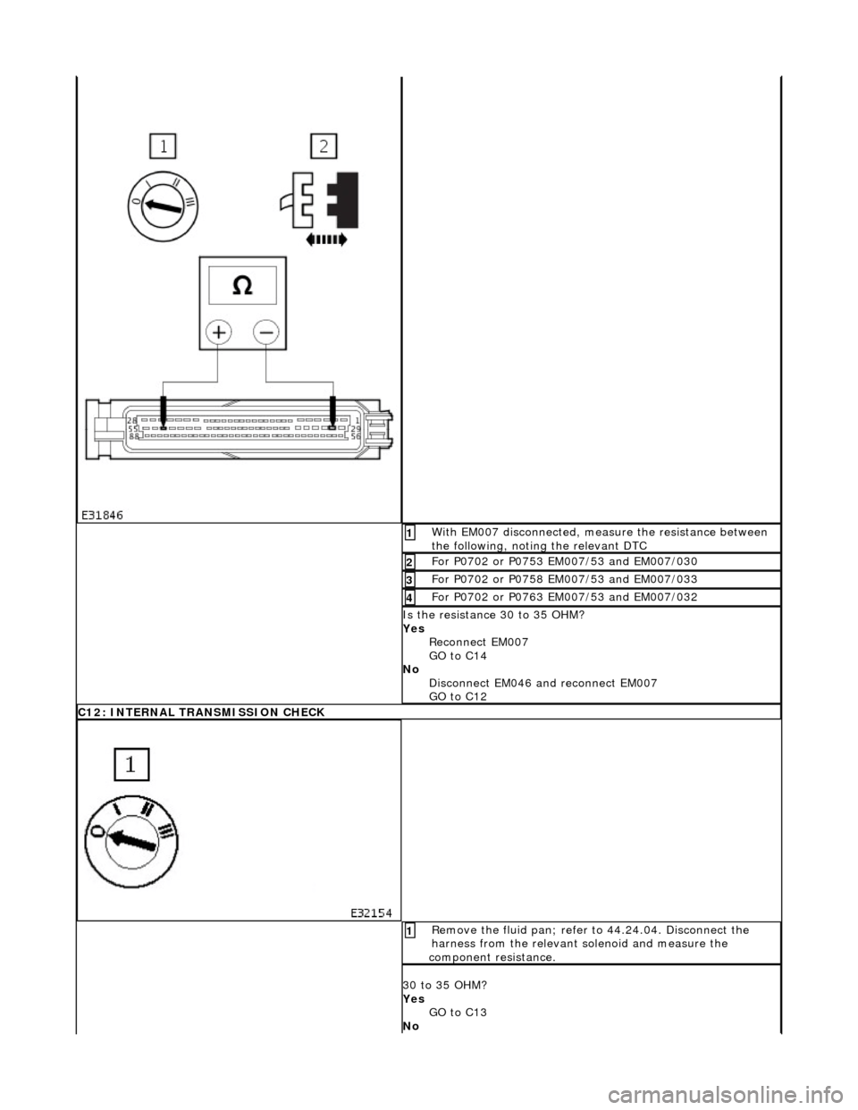
With EM007 disconnected, measure the resistance between
the following, noting the relevant DTC 1
For P0702 or P0753 EM007/53 and EM007/030 2
For P0702 or P0758 EM007/53 and EM007/033 3
For P0702 or P0763 EM007/53 and EM007/032 4
Is the resistance 30 to 35 OHM?
Yes Reconnect EM007
GO to C14
No Disconnect EM046 and reconnect EM007
GO to C12
C12: INTERNAL TRANSMISSION CHECK
Remove the fluid pan; refer to 44.24.04. Disconnect the
harness from the relevant solenoid and measure the
component resistance. 1
30 to 35 OHM?
Yes GO to C13
No
Page 1305 of 2490
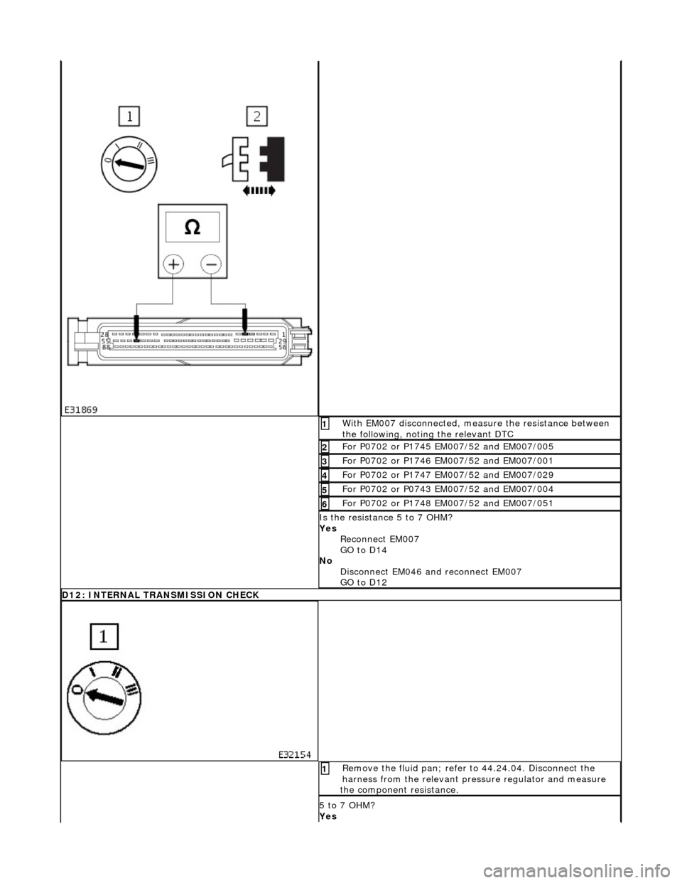
With EM007 disconnected, measure the resistance between
the following, noting the relevant DTC 1
For P0702 or P1745 EM007/52 and EM007/005 2
For P0702 or P1746 EM007/52 and EM007/001 3
For P0702 or P1747 EM007/52 and EM007/029 4
For P0702 or P0743 EM007/52 and EM007/004 5
For P0702 or P1748 EM007/52 and EM007/051 6
Is the resistance 5 to 7 OHM?
Yes Reconnect EM007
GO to D14
No Disconnect EM046 and reconnect EM007
GO to D12
D12: INTERNAL TRANSMISSION CHECK
Remove the fluid pan; refer to 44.24.04. Disconnect the
harness from the relevant pres sure regulator and measure
the component resistance. 1
5 to 7 OHM?
Yes
Page 1336 of 2490
it overflows from the plug orifice. 2. CAUTION: It is essential that only the specified
fluid is used.
Wait until the flow of fluid has reduced to a trickle.
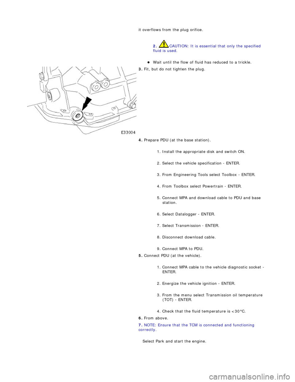
3. Fit, but do not tighten the plug.
4. Prepare PDU (at the base station).
1. Install the appropriat e disk and switch ON.
2. Select the vehicle specification - ENTER.
3. From Engineering Tools select Toolbox - ENTER.
4. From Toolbox select Powertrain - ENTER.
5. Connect MPA and download cable to PDU and base station.
6. Select Datalogger - ENTER.
7. Select Transmission - ENTER.
8. Disconnect download cable.
9. Connect MPA to PDU.
5. Connect PDU (at the vehicle).
1. Connect MPA cable to the vehicle diagnostic socket -
ENTER.
2. Energize the vehicle ignition - ENTER.
3. From the menu select Transmission oil temperature (TOT) - ENTER.
4. Check that the fluid temperature is <30°C.
6. From above.
7. NOTE: Ensure that the TCM is connected and functioning
correctly.
Select Park and start the engine.