Key transponder module JAGUAR X308 1998 2.G Workshop Manual
[x] Cancel search | Manufacturer: JAGUAR, Model Year: 1998, Model line: X308, Model: JAGUAR X308 1998 2.GPages: 2490, PDF Size: 69.81 MB
Page 1849 of 2490

2. Remove the bolt (1) lower fixing
3. Remove the nut (1) lower fixing
Remove the column assembly from the vehicle
12. Remove the duct - driver footwell
Remove screw (1)
13. Remove the key tr ansponder module
1. Remove the screws (2) module to fascia bracket
2. Disconnect the multiplug
Reposition the transponder to gain access
14. Remove the illumination module
1. Release the module from its location
2. Disconnect the multiplug
15. Remove the plenum brace
1. Remove the bolt (1) tunnel fixing
2. Remove the bolt (1) upper fixing
3. Slide the diagnostic socket off the brace
Page 2008 of 2490

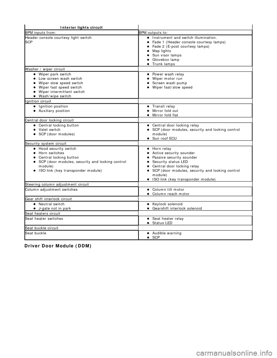
Driver Door Module (DDM)
Interior lights circuit
BPM inputs from: BPM outputs to:
Header console courtesy light switch
SCPInstrument and switch illumination. Fade 1 (Header console courtesy lamps) Fade 2 (E-post courtesy lamps) Map lights Sun visor lamps Glovebox lamp Trunk lamps
Washer / wiper circuit
Wiper park switch Low screen wash switch Wiper slow speed switch Wiper fast speed switch Wiper intermittent switch Wash/wipe switch
Power wash relay Wiper motor run Screen wash pump Wiper fast/slow speed
Ignition circuit
Ignition position Auxiliary position Transit relay Mirror fold out Mirror fold flat
Central door locking circuit
Central locking button Valet switch SCP (door modules)
Central door locking relay SCP (door modules, security and locking control
module)
Sun roof ECU
Security system circuit
Hood security switch Horn switches Central locking button SCP (door modules, security and locking control
module)
ISO link (key transponder module)
Horn relay Active security sounder Passive security sounder Security status LED Central door locking relay SCP (door modules, security and locking control
module)
ISO link (key transponder module)
Steering column adjustment circuit
Column adjustment switchesColumn tilt motor Column reach motor
Gear shift interlock circuit
Neutral switch J-gate not in park Keylock solenoid Gearshift interlock solenoid
Seat heaters circuit
Seat heater switchesSeat heater relay Status LED
Seat buckle circuit
Seat buckleAudible warning SCP
Page 2247 of 2490

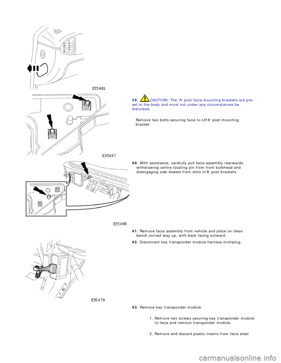
39. CAUTION: The 'A' post facia mounting brackets are pre-
set to the body and must no t under any circumstances be
disturbed.
Remove two bolts securing facia to LH'A' post mounting
bracket.
40. With assistance, carefully pull facia assembly rearwards,
withdrawing centre locating pin from front bulkhead and
disengaging side dowels from slots in'A' post brackets.
41. Remove facia assembly from vehicle and place on clean
bench correct way up, with back facing outward.
42. Disconnect key transponder module harness multiplug.
43. Remove key transponder module.
1. Remove two screws securi ng key transponder module
to facia and remove transponder module.
2. Remove and discard plastic inserts from facia steel
Page 2258 of 2490

31. Connect body processor module harness multiplug to facia
harness and tighten captive securing bolt.
32. Install illumination control module on facia. mounting.
1. Connect module to facia harness multiplug.
2. Slide module downward to secure on mounting bracket.
33. Install new key transponder module securing screw plastic
inserts to facia. Position key transponder module in facia and
install securing screws.
34. Connect key transponder module harness multiplug to facia
harness.
Page 2322 of 2490

Wipers and Washers - Windshield Wiper/Washer Switch
Removal and Installation
Removal
1. Ensure that steering wheel is in the straight ahead, fully
lowered and fully ex tended position.
2. Remove battery cover and disc onnect ground cable from
battery terminal. Refer to 86.15.19.
3. WARNINGS:
FOLLOWING DISCONNECTION OF THE BATTERY, A PERIOD
OF AT LEAST ONE MINUTE MUST BE ALLOWED TO ELAPSE
BEFORE ANY WORK IS CARRIED OUT ON AN AIR BAG MODULE.
FOLLOWING TEN YEARS IN SERVICE, AN AIR BAG MODULE
MUST BE REMOVED AND DISPOSED OF IN THE APPROVED
MANNER, AND A NEW AIR BAG MUST BE FITTED.
AIR BAGS CONTAIN A CHEMICAL IRRITANT. IF AN AIR BAG
IS RENEWED, THE ORIGINAL UNIT MUST BE DISPOSED OF IN
ACCORDANCE WITH CURRENT SAFETY PROCEDURES.
IN THE EVENT OF A FAULT RUPTURING THE 10A BATTERY
SUPPLY FUSE (F4 LOCATED IN THE FUSE-BOX AT THE DRIVER'S
END OF THE FASCIA), THE FUSE MUST NOT BE RENEWED UNTIL
THE AIRBAG/SRS SYSTEM HAS BEEN DE-ACTIVATED. FUSES OF
ANY OTHER VALUE MUST NEVER BE USED, AS THIS CAN CAUSE
DISARM FAILURE.
Remove driver airbag. Refer to 76.73.39.
4. Remove steeri ng wheel.
5. Remove steering column lowe r cowl. Refer to 76.46.03.
6. Remove steering column upper cowl. Refer to 76.46.02.
7. Remove driver side unders cuttle. Refer to 76.46.11.
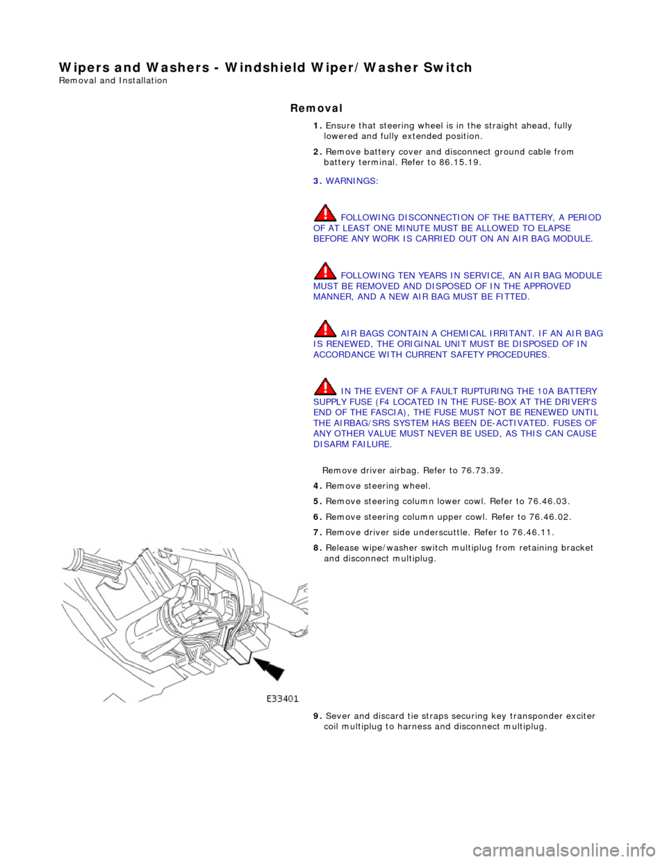
8. Release wipe/washer switch mult iplug from retaining bracket
and disconnect multiplug.
9. Sever and discard tie straps se curing key transponder exciter
coil multiplug to harness and disconnect multiplug.