wheel bolts JAGUAR X308 1998 2.G Workshop Manual
[x] Cancel search | Manufacturer: JAGUAR, Model Year: 1998, Model line: X308, Model: JAGUAR X308 1998 2.GPages: 2490, PDF Size: 69.81 MB
Page 61 of 2490
Suspension System - General Information - Front Camber and Caster
Adjust
ment
Gen
eral Procedures
• NOTE: Before any work is commenced, th e vehicle must be checked to establish that it conforms to the Jaguar original
specification, e.g. wheels, ti res, tire pressures, etc.
• NOTE: The vehicle must be unladen and the fuel tank full when measuring suspension geometry.
1.
Road test the vehicle to establish the exact nature of the
complaint, e.g. pulling to one side, wander.
2. Measure the suspension geometry, fill in the 'Suspension
Geometry Record Form', and co ntact Jaguar Technical Support
for assistance.
3. Technical Support will give advice on the course of action to be
taken to rectify the problem.
4. Each lower wishbone pivots on and is secured to the front
crossbeam by two fulcrum bolts. A circular eccentric flange
formed under the hexagonal head of each fulcrum bolt, has
raised graduation marks to indicate radial position. A washer
with a 'D' shaped hole locates on a flat on the threaded section
of each bolt. This ensures that the washer rotates with the bolt,
maintaining an eccentric position corresponding with the
flanged head. The outer face of the washer is punch marked,
ensuring correct instal lation with the chamfered face inwards.
This permits the washer to rotate freely in the crossbeam cam
reaction plate during a djustm ent. Each fulcrum bolt and
washer are secured by a self locking nut.
On rotation of the bolt, lateral movement of the eccentric flange
and washer is restricted by the cam plate faces, forcing the bolt
shank to move laterally in the crossbeam slots. Lateral
movement of the bolt shank re sults in corresponding inward
and outward movement of th e wishbone arm, effecting
adjustment of wh eel alignment.
Rotation of the front fulcrum bolt principally adjusts wheel
caster angle, with a small amount of camber angle change.
Adjustment of the rear fulcrum bo lt mainly alters wheel camber
angle with a small amount of caster angle change.
On vehicles with VIN up to 833124, fulcrum bolt eccentric
flanges have raised graduation marks representing 15 degree
increments of bolt rotati on from 0 to 90 degrees.
On vehicles with VIN from 833125, the fulcrum bolt graduation
marks represent bolt shank ho rizontal movement in 1mm
increments from 0 to 3mm.
The upper wishbone and fulcrum shaft are not adjustable and
play no part in steering geometry adjustment.
Page 70 of 2490
Upper
Wishbones
Each
upper wi
shbone assembly is a on
e-piece steel forging incorporating:
A pres
s-fit ball joint.
Press-fi
t bushes for location of the upper fulcrum bolt.
Lower Wishbones
Each l
o
wer wishbone comprising
forged steel front and rear arms bolted together, incorporates:
A p
ress-fit ball joint in the outer extremity of the rear arm.
Press-f
i
t bushes for location of the lower fulcrum bolts
Locati
on for the shock absor
b
er lower mounting plates.
Vertica l Links
The vertical
links are of forged steel
wi
th integral steering arms. Each is suppo rted between the upper and lower wishbones
by two ball joints and carries:
Front hub
Brake ca
liper and disc shield assembly
ABS se
nsor
.
Front Hub
s
Each f
o
rged steel front hub accommodates sealed for life cartridge
type wheel bearings, and carries:
The brake rotor assembl
y.
A
h
ub nut with toothed, integral ABS rotor.
Su
s
pension spring pi
n locking device.
Front Road
Springs
The road spri
ng
s are of coil type with their
rating dependent upon vehicle specification
Ea
ch spring is installed between the suspension crossbeam location and the lower wishbone spring pan.
Ru
bber seats ar
e installed betw
een the spring and the crossb eam and the spring pan.
Front Shock A
bsorbers
Th
e
shock absorbers are telescopic hydrau
lically operated units. Optional adaptive damping units incorporate a solenoid-
operated control valve at their upper extremity.
Each shoc
k absorber is installed between the lowe
r wishbone rear arm and a recess in the body.
The l
o
wer end of the shock absorber is se
cured to plates on the wishbone by a bolt that also serves as a pivot.
The u
pper en
d of each shock absorber is secured to the body location by a single nut.
Front Sta
b
ilizer Bar
A
front stabil
izer bar installed on all vehicles
is rated according to suspension specification.
Opera
tion
As each road wheel r
i
ses, move
ment is transmitted through the vertical link assembly to the lower wishbone. The resulting
rise of the wishbone compresses the road spring and partially telescopes the shock absorber. During this action, the spring
absorbs associated shocks and the shock absorber minimizes sprin
g os c
illation.
Du
ring cornering, vehicle weight
is transferred to the outer road wheel with a resulting tendency for the inner wheel to lift.
The stabilizer bar assists in minimizing this tendency by transf erring a proportion of potential lift of the inner wheel to the
outer wheel. This result s in enhanced body stability with improved corner ing capabilities.
Page 78 of 2490

Front Suspension - Rear Lower Arm
Remo
val and Installation
Remov
a
l
CAUTI
O
N: Replacement of
nuts and bolts: Various thread-locking devices are used on nuts and bolts throughout the
vehicle. These devices restrict the number of times a nut or bolt can be used. Refer to Section 100-00 for further
information.
S p
ecial Tool(s)
R
o
ad spring compressor
204-111 (JD115)
Taper separator
2
11-098 (JD 100)
Ball
Jo
int Taper Separator
204-192 (JD 219)
Bal l
joint splitter
204-293
1. Ra
ise front of vehicle and support on stands. Refer to Section
100-02.
2. Remove appropriate road wheel. Refer to Section 100-02.
3. CAUTIO
N: Do not suspend caliper from brake hose as
this will damage the hose.
Remove brake calipers from carriers. 1. Remove caliper spring clip.
2. Remove guide pin dust caps.
3. Slacken and withdraw guide pins.
4. Remove caliper from carrier and tie to suspension mounting bracket.
4. Ra
ise vehicle further to provid
e access for Special Tool 204-
Page 88 of 2490
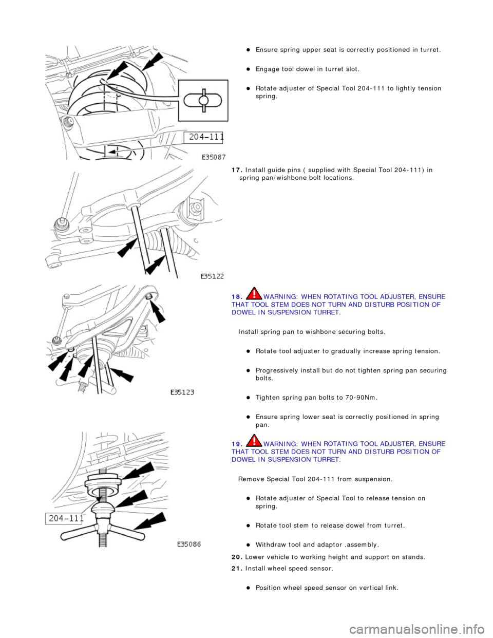
Ensure spring
upper se
at is correctly positioned in turret.
Engage tool dowel in turret slo
t.
R
o
tate adjuster of Special Tool 204-111 to lightly tension
spring.
17 . Ins
tall guide pins ( supplied with Special Tool 204-111) in
spring pan/wishbone bolt locations.
18 . WARNING: WHE
N ROTATING TOOL ADJUSTER, ENSURE
THAT TOOL STEM DOES NOT TU RN AND DISTURB POSITION OF
DOWEL IN SUSPENSION TURRET.
Install spring pan to wishbone securing bolts.
Ro t
ate tool adjuster to gradua
lly increase spring tension.
Pr
ogressively install but do no
t tighten spring pan securing
bolts.
Tigh ten spring pan
bolts to 70-90Nm.
Ensure spri
ng
lower seat is co
rrectly positioned in spring
pan.
19 . WARNING: WHE
N ROTATING TOOL ADJUSTER, ENSURE
THAT TOOL STEM DOES NOT TU RN AND DISTURB POSITION OF
DOWEL IN SUSPENSION TURRET.
Remove Special Tool 204-111 from suspension.
Rotat
e adjuster of Special Tool to release tension on
spring.
R otate
tool stem to release dowel from turret.
With
draw tool and adaptor
.assembly.
20
. Lower vehi
cle to working heig
ht and support on stands.
21. Install wheel speed sensor.
Positi
on wheel speed sensor on vertical link.
Page 90 of 2490

Front Suspension - Rear Lower Arm Bushing
Remo
val and Installation
Remov
a
l
CAUTI
O
N: Replacement of
nuts and bolts: Various thread-locking devices are used on nuts and bolts throughout the
vehicle. These devices restrict the number of times a nut or bolt can be used. Refer to Section 100-00 for further
information.
S p
ecial Tool(s)
R
o
ad spring compressor
204-111 (JD115)
Taper separator
2
11-098 (JD 100)
Ball
Jo
int Taper Separator
204-192 (JD 219)
Bal l
joint splitter
204-293
1. Ra
ise front of vehicle and support on stands. Refer to Section
100-02.
2. Remove appropriate road wheel. Refer to Section 100-02.
3. CAUTIO
N: Do not suspend caliper from brake hose as
this will damage the hose.
Remove brake calipers from carriers. 1. Remove caliper spring clip.
2. Remove guide pin dust caps.
3. Slacken and withdraw guide pins.
4. Remove caliper from carrier and tie to suspension mounting bracket.
4. Ra
ise vehicle further to provid
e access for Special Tool 204-
Page 102 of 2490
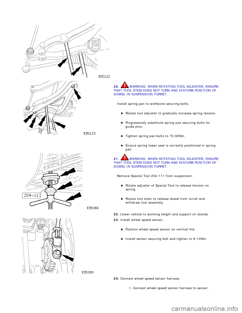
20. WARNING: WHE
N ROTATING TOOL ADJUSTER, ENSURE
THAT TOOL STEM DOES NOT TU RN AND DISTURB POSITION OF
DOWEL IN SUSPENSION TURRET.
Install spring pan to wishbone securing bolts.
Ro t
ate tool adjuster to gradua
lly increase spring tension.
Pr
ogressively substitute spri
ng pan securing bolts for
guide pins.
Tighten spring pan
bolts to 70-90Nm.
Ensure spri
ng
lower seat is co
rrectly positioned in spring
pan.
21 . WARNING: WHE
N ROTATING TOOL ADJUSTER, ENSURE
THAT TOOL STEM DOES NOT TU RN AND DISTURB POSITION OF
DOWEL IN SUSPENSION TURRET.
Remove Special Tool 204-111 from suspension.
Rotat
e adjuster of Special Tool to release tension on
spring.
R o
tate tool stem to release dowel from turret and
withdraw tool assembly.
22 . Lower vehi
cle to working heig
ht and support on stands.
23 . Inst
all wheel speed sensor.
Posi
ti
on wheel speed sensor on vertical link.
Instal
l sensor securing bolt
and tighten to 8-10Nm.
24. Connect wheel speed sensor harness.
1. Connect wheel speed sensor harness to sensor.
Page 109 of 2490
Front Suspension - Spring
Re
moval and Installation
Remov
al
CAUTI
ON: Replacement of
nuts and bolts: Various thread-locking devices are used on nuts and bolts throughout the
vehicle. These devices restrict the number of times a nut or bolt can be used. See section 100-00 for information.
S
pecial Tool(s)
R
oad spring compressor
204-111 (JD115)
Taper separator
211-098 (JD 100)
Ball
Joint Taper Separator
204-192 (JD 219)
1. R
aise front of vehicle to provid
e access for Special Tool 204-
111. Refer to Section 100-02
2. Remove appropriate road wheel. Refer to Section 100-02.
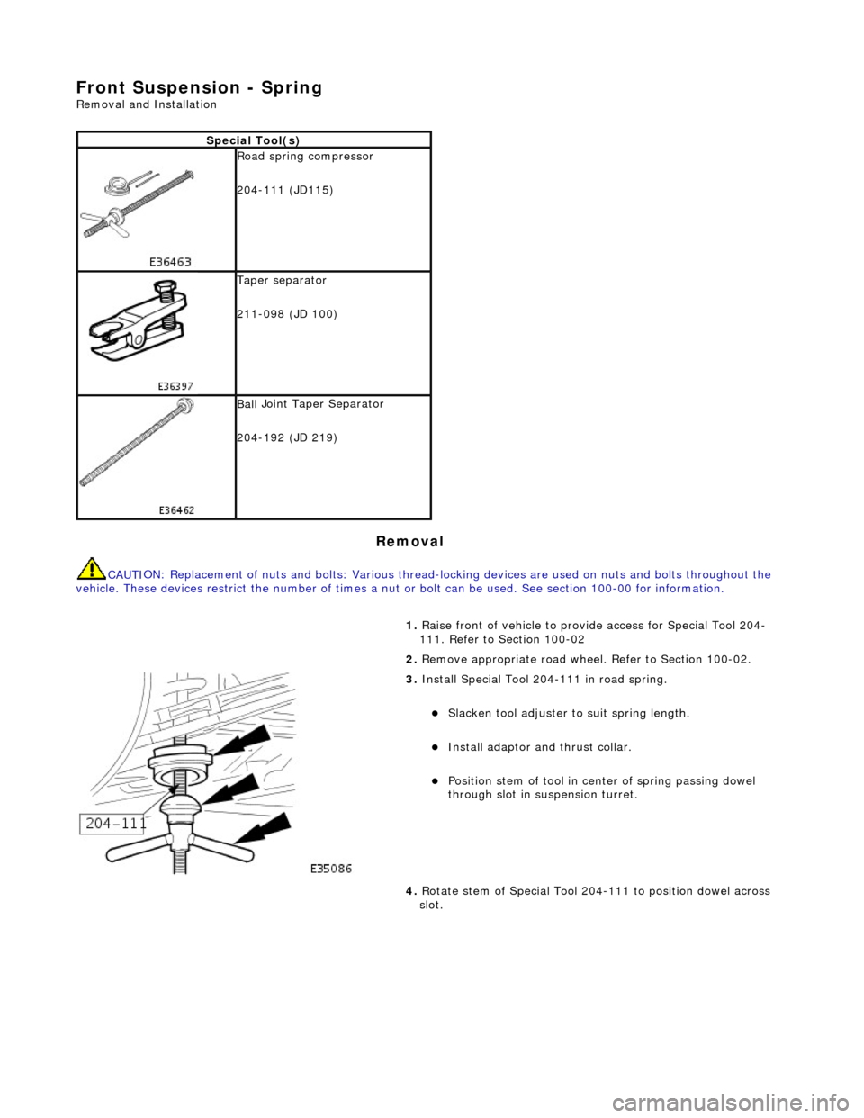
3. Ins
tall Special Tool 204-111 in road spring.
Sl
acken tool adjuster to suit spring length.
Install adaptor
and thrust collar.
Posit
ion stem of tool in center of spring passing dowel
through slot in su spension turret.
4. Rotate stem of Special Tool 204-111 to position dowel across
slot.
Page 112 of 2490

Rot
ate tool adjuster to gradua
lly increase spring tension.
Pr
ogressively substitute spri
ng pan securing bolts for
guide pins.
Ti ghten spring pan
securing bolts to 70-90Nm.
6. WARNING: WHE N
ROTATING TOOL ADJUSTER, ENSURE
THAT TOOL STEM DOES NOT TU RN AND DISTURB POSITION OF
DOWEL IN SUSPENSION TURRET.
Remove Special Tool 204-111 from suspension.
Ensure spri ng
lower rubber seat
is correctly positioned and
fully seated.
R otat
e adjuster of Special Tool to release tension on
spring.
7. Ro
tate tool stem to release
dowel from turret and withdraw
tool assembly.
8. Lower vehicle to working heig ht and support on stands.
9. Install road wheel. Re fer to Section 100-02.
10. Raise vehicle, remove stands and lower vehicle onto road
wheels.
Page 113 of 2490
Front Suspension - Spring Seat
Re
moval and Installation
Remov
al
CAUTI
ON: Replacement of
nuts and bolts: Various thread-locking devices are used on nuts and bolts throughout the
vehicle. These devices restrict the number of times a nut or bolt can be used. See section 100-00 for information.
S
pecial Tool(s)
R
oad spring compressor
204-111 (JD115)
Taper separator
211-098 (JD 100)
Ball
Joint Taper Separator
204-192 (JD 219)
1. R
aise front of vehicle to provid
e access for Special Tool 204-
111. Refer to Section 100-02
2. Remove appropriate road wheel. Refer to Section 100-02.
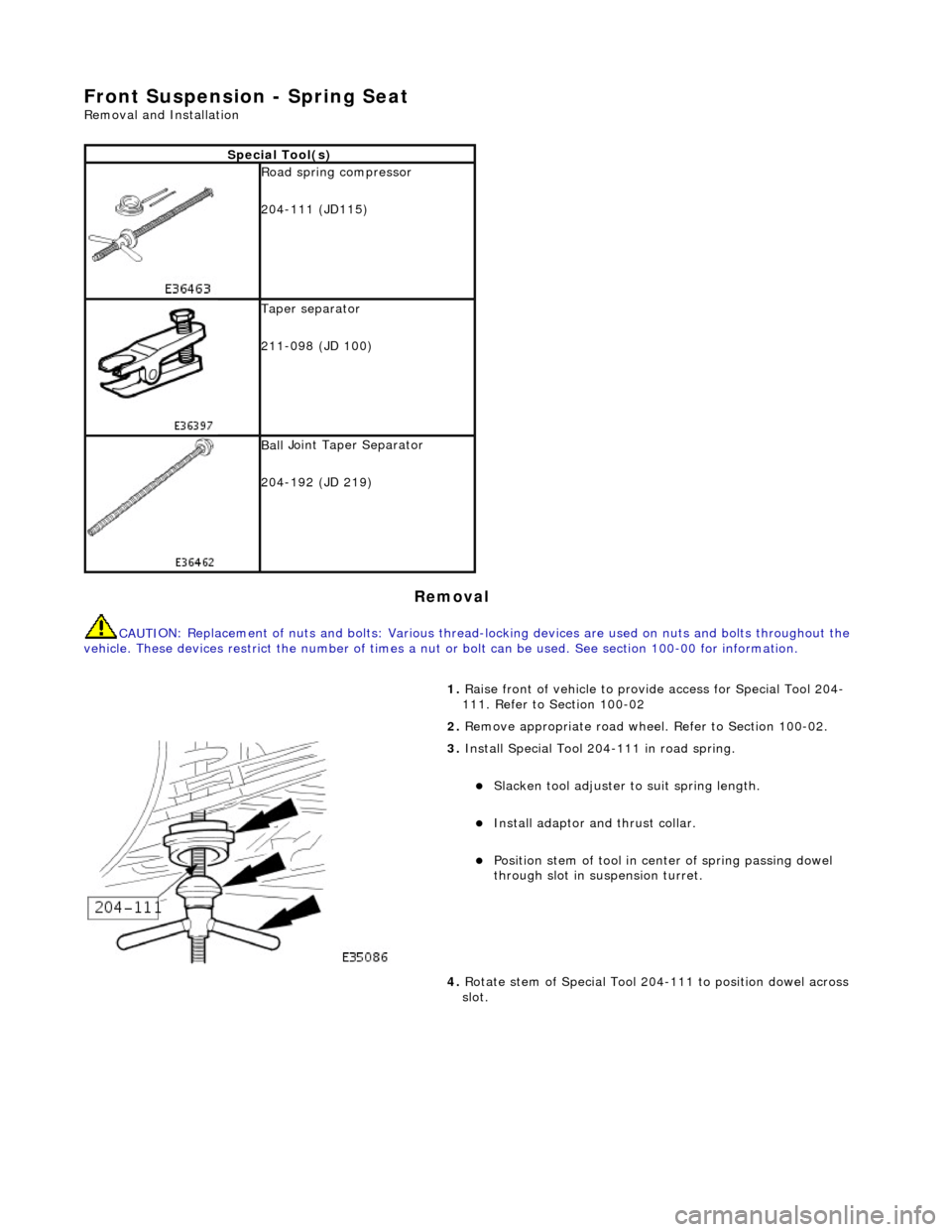
3. Ins
tall Special Tool 204-111 in road spring.
Sl
acken tool adjuster to suit spring length.
Install adaptor
and thrust collar.
Posit
ion stem of tool in center of spring passing dowel
through slot in su spension turret.
4. Rotate stem of Special Tool 204-111 to position dowel across
slot.
Page 116 of 2490

Align sp
ring pan with lower wishbone bolt locations.
Rot
ate tool adjuster to gradua
lly increase spring tension.
P
r
ogressively install but do no
t tighten spring pan securing
bolts.
Ti ghten spring pan
securing bolts to 70-90Nm.
Ensure spri
ng
lower rubber seat is correctly positioned in
spring pan.
6. WARNING: WHE N
ROTATING TOOL ADJUSTER, ENSURE
THAT TOOL STEM DOES NOT TU RN AND DISTURB POSITION OF
DOWEL IN SUSPENSION TURRET.
Remove Special Tool 204-111 from suspension.
Rotat
e adjuster of Special Tool to release tension on
spring.
R otate
tool stem to release dowel from turret.
With
draw tool and adaptor
.assembly.
7.
Lower vehi cle to work
ing heig
ht and support on stands.
8. Install road wheel. Re fer to Section 100-02.
9. Raise vehicle, remove stands and lower vehicle onto road
wheels.
10. Carry out steering geometry an d wheel alignment checks and
if necessary adjust. Refer to 57.65.01.
11. Carry out steering geometry an d wheel alignment checks and
if necessary adjust. Refer to 57.65.01.