STARTER JAGUAR X308 1998 2.G Workshop Manual
[x] Cancel search | Manufacturer: JAGUAR, Model Year: 1998, Model line: X308, Model: JAGUAR X308 1998 2.GPages: 2490, PDF Size: 69.81 MB
Page 13 of 2490

Removal and Installation
Fuel Injection Supply Manifo ld LH
(19.60.05)
Fuel Injection Supply Manifold RH (19.60.04)
Fuel Injection Supply Manifold Pipe (19.41.04)
Fuel Injector Vehicles Without: Supercharger (18.10.01)
Fuel Injector Vehicles With: Supercharger (18.10.01)
Fuel Injectors Vehicles With: Supercharger (18.10.02)
Throttle Body (19.70.04)
Throttle Body Gasket (19.70.07)
303‐05: Accessory Drive
Descriptio
n and Operation
Accessory Drive
Removal and Installation
Accessory Drive Belt (12.10.40) ‐ 3.2L NA V8 ‐ AJ26/4.0L NA V8 ‐ AJ27
Accessory Drive Belt (12.10.40) ‐ 4.0L SC V8 ‐ AJ26
Accessory Drive Belt Idler Pulley (12.10.43) ‐ 3.2L NA V8 ‐ AJ26/4.0L NA V8 ‐ AJ27
Accessory Drive Belt Idler Pulle
y (12.10.43) ‐ 4.0L SC V8 ‐ AJ26
Accessory Drive Belt Tensioner (12.10.41) ‐ 3.2L NA V8 ‐ AJ26/4.0L NA V8 ‐ AJ27
Accessory Drive Belt Tensioner (12.10.41) ‐ 4.0L SC V8 ‐ AJ26
Supercharger Belt (18.50.08)
Supercharger Belt Idler Pulley (18.50.09)
Supercharger Belt Tensioner (18.50.24)
303‐06: Starting System
Description and Operati
on
Starting System
Diagnosis and Testing
Starting System
Inspection and Verification
Diagnostic Trouble Code (DTC) Index
Pinpoint Tests
Removal and Installation
Starter Motor (86.60.01)
Page 516 of 2490
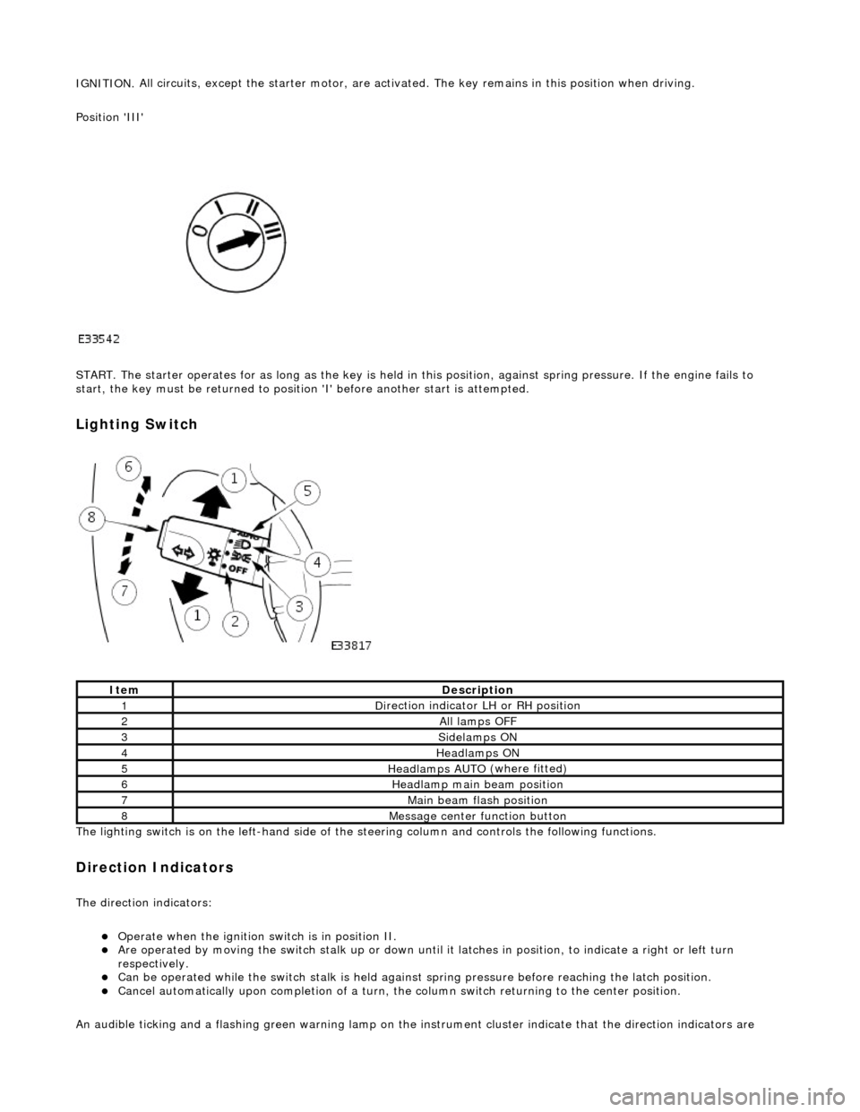
IGNITION.
All circuits, except the star
ter motor, are activated. The key rema ins in this position when driving.
Position 'III'
START. The starter operates for as long as the key is held in this position, ag ainst spring pressure. If the engine fails to
start, the key must be returned to position 'I' befo re another start is attempted.
Lighting Switch
The li
ghting switch is on the left-h
and side of the steering column and controls the following functions.
Direction Indicators
The direction in
dicators:
Operate
when the ignition switch is in position II.
Are operat
ed by movi
ng the switch stalk up or down until it latches in position, to in
dicate a right or left turn
respectively.
Can be o p
erated while the switch stalk is held against
spring pressure before reaching the latch position.
Cancel
automatically upon completion of a turn, the
column switch returning to the center position.
An audible ticking and a flashing green warning lamp on the in strument cluster indicate that the direction indicators are
Ite
m
De
scr
iption
1D
i
rection indicator LH or RH position
2All lamps OFF
3Side
lamps ON
4Headlamps ON
5Headlamps AUT O
(where fitted)
6He
adlam
p main beam position
7Mai
n
beam flash position
8M
e
ssage center function button
Page 528 of 2490
Speed an
d load
Coo
l
ant temperature
Ti
me el
apsed from start up
Cl
osed l
oop fuelling
Determination of the vapour concentration is made by stepped opening of the EVAP valve and subsequent monitoring of the
fuelling correction. This function is performed prior to purging, so that at the onse t of purging the EVAP valve can be set to
the optimum position. Should the ECM be unable to determine the concentration before purging, a default value is
employed, which is then modified whilst purging is in progress.
When the purging process is operational th e ECM modifies the basic fuelling calculation to maintain the correct air / fuel
ratio.
Purging is inhibited during fuel cut-off and stability / traction control intervention.
Coolant Temperature Sen
sor
Th
e
sensor outputs a voltage to the ECM which decreases as temperature increases.
Cooling Fans
In response to engi
ne coolant temperat
u
re and climate control system demand, the ECM will energize the cooling fans.
Climate Control Compressor
The E
C
M will allow the compressor clutch to be engaged if th
e engine temperature and load demand are normal. Should the
driver require maximum engine powe r or the coolant temperature be high, the request will be denied.
Cranking Signal
The ECM reacts to a signal fr
om th
e Body Processor Module (BPM) when the starter motor relay is energi
zed. This signal is
used to trigger starting, fu el and ignition strategies.
Engine Speed and Cranksh
aft Position
Engine
speed and cran
k position are moni
tored by a sensor which is mounted on the cylinder block (flywheel housing)
behind the crankshaft drive plat e. It indicates rotational speed to the ECM in the form of 12 pulses per crank revolution.
Engine speed is used for synchronization of fuel an d ignition systems, as well as other functions.
Camshaft Position
The ca
mshaft position sensor is mounted at
the rear of Bank 2 cylinder head on the inlet side and provides one signal every
720 degrees of crankshaft rotation. The signal, in conjunction with the signal from the crankshaft position sensor, indicates
to the ECM that the piston of cylinder 1A is approaching TDC on the compression stroke.
Variable Valve
Timing (Where Fitted)
By energi
si
ng a solenoid to allow the pass
age of pressurized oil on each of the inle t camshaft drives, the ECM can vary by a
single stepped amount, the relati ve timing of the inlet valves.
Ign
ition
Ignit
i
on spark is produced by
individual on-plug coil units.
There are two ignition amplifiers; module #1 drives coils 1A, 2B, 3B and 4A, whilst module #2 drives coils 1B, 2A, 3A and
4B. The ECM controls the amplifiers.
Page 906 of 2490
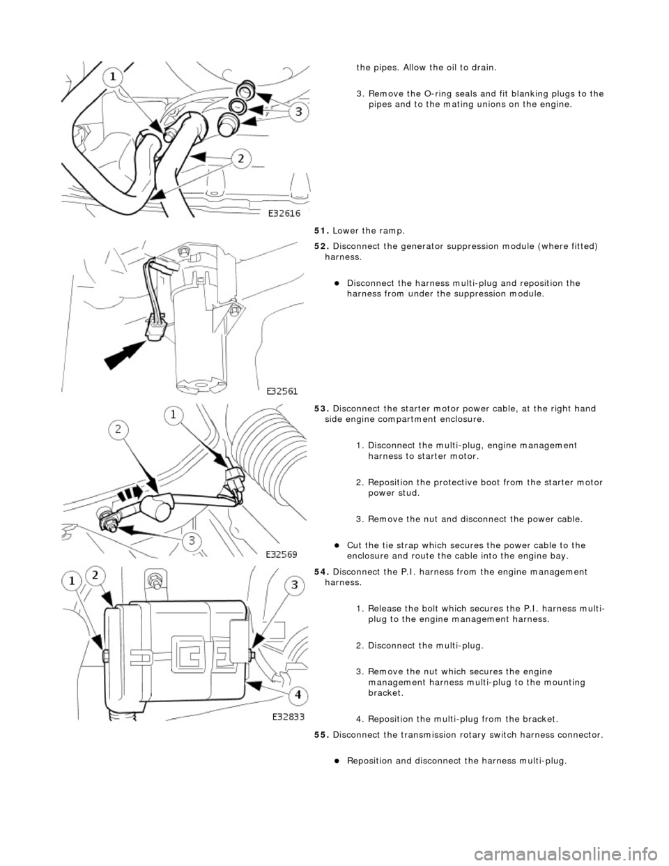
the pipes. Allow the oil to drain.
3. Remove the O-ring seals and fit blanking plugs to the
pipes and to the mating unions on the engine.
51. Lower the ramp.
52. Disconnect the generator suppres sion module (where fitted)
harness.
Disconnect the harness multi-plug and reposition the
harness from under the suppression module.
53. Disconnect the starter motor power cable, at the right hand
side engine compartment enclosure.
1. Disconnect the multi-plug, engine management harness to starter motor.
2. Reposition the protective boot from the starter motor
power stud.
3. Remove the nut and disc onnect the power cable.
Cut the tie strap which secures the power cable to the
enclosure and route the cable into the engine bay.
54. Disconnect the P.I. harness from the engine management
harness.
1. Release the bolt which secures the P.I. harness multi-plug to the engine management harness.
2. Disconnect the multi-plug.
3. Remove the nut which secures the engine management harness multi-plug to the mounting
bracket.
4. Reposition the multi-plug from the bracket.
55. Disconnect the transmission rota ry switch harness connector.
Reposition and disconnect the harness multi-plug.
Page 917 of 2490
WARNING: B
EFORE PROCEEDING, IT IS ESSENTIAL THAT
THE WARNING NOTES GIVEN IN SECTION 100-00 (UNDER
THE HEADING 'SAFETY PRECAUTION S') ARE READ AND UNDERSTOOD.
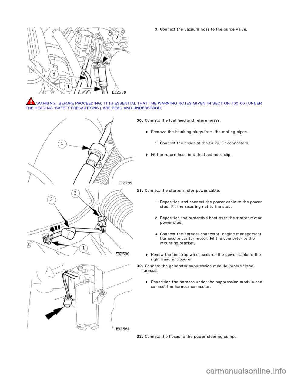
3.
Connect the vacuum hose to the purge valve.
30
.
Connect the fuel feed and return hoses.
R
emove the blanking plugs
from the mating pipes.
1. Connect the hoses at the Quick Fit connectors.
F
it the return hose into the feed hose clip.
31
.
Connect the starter motor power cable.
1. Reposition and connect the power cable to the power stud. Fit the securing nut to the stud.
2. Reposition the protective boot over the starter motor power stud.
3. Connect the harness connector, engine management harness to starter motor. Fit the connector to the
mounting bracket.
R
enew the tie strap which secures the power cable to the
right hand enclosure.
32
.
Connect the generator suppressi on module (where fitted)
harness.
Re
position the harn
ess under the suppression module and
connect the harness connector.
33. Connect the hoses to the power steering pump.
Page 926 of 2490
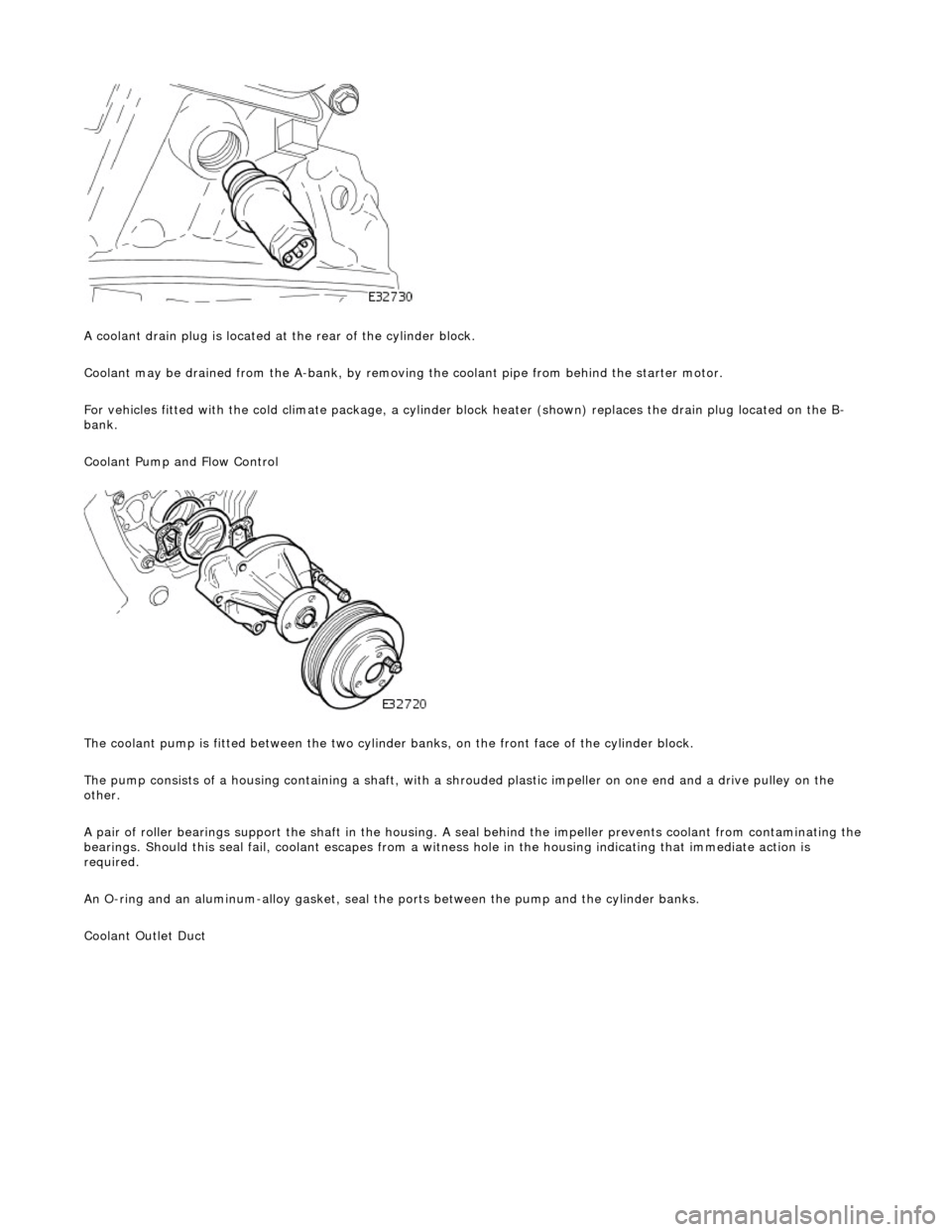
A coola n
t drain plug is located at the rear of the cylinder block.
Coolant may be drained from the A-bank, by removing the coolant pipe from behind the starter motor.
For vehicles fitted with the cold climate package, a cylinder block heater (shown) replaces the drain plug located on the B-
bank.
Coolant Pump and Flow Control
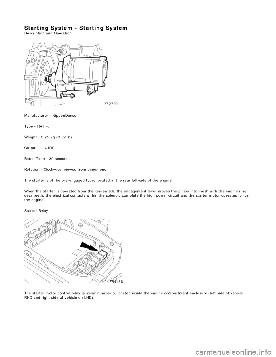
The coolant pump is fitted between the two cylinder banks, on the front face of the cylinder block.
The pump consists of a housing containing a shaft, with a sh rouded plastic impeller on one end and a drive pulley on the
other.
A pair of roller bearings support the shaft in the housing. A seal behind the impeller prevents coolant from contaminating the
bearings. Should this seal fail, coolant escapes from a witness hole in the housin g indicating that immediate action is
required.
An O-ring and an aluminum-alloy gasket, seal the ports between the pump and the cylinder banks.
Coolant Outlet Duct
Page 1062 of 2490
Starting System - Starting System
Description and Operation
Manufacturer - NipponDenso
Type - RA1.4.
Weight - 3.75 kg (8.27 lb)
Output - 1.4 kW
Rated Time - 30 seconds
Rotation - Clockwise, viewed from pinion end
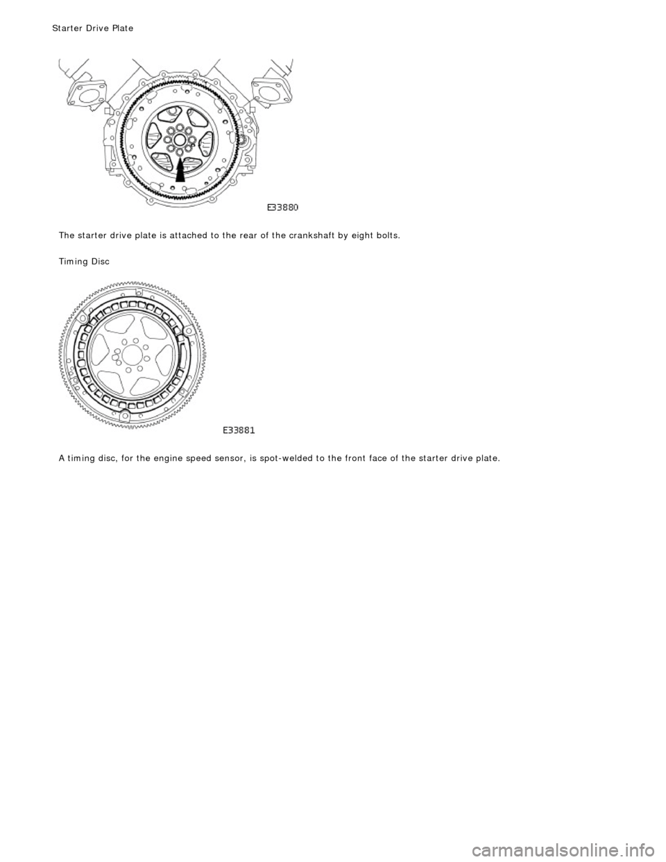
The starter is of the pre-engaged type; loca ted at the rear left-side of the engine.
When the starter is operated from the key-switch, the engagement lever moves the pinion into mesh with the engine ring
gear teeth, the electrical contacts within the solenoid complete the high power circuit and the starter motor operates to turn
the engine.
Starter Relay
The starter motor control relay is, relay nu mber 5, located inside the engine compartment enclosure (left side of vehicle
RHD and right side of vehicle on LHD).
Page 1063 of 2490
Th
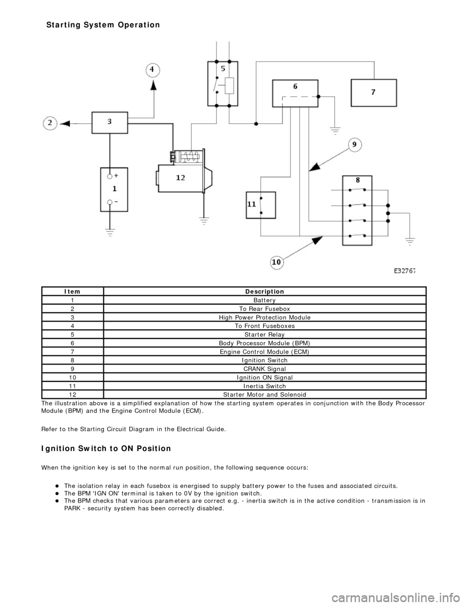
e starter drive plate is attached to the rear of the crankshaft by eight bolts.
Timing Disc
A timing disc, for the engine speed sensor, is spot-w elded to the front face of the starter drive plate.
Starter Drive Plate
Page 1064 of 2490
The il
lustration above is a simplified expl
anation of how the starting system operates in conjunction with the Body Processor
Module (BPM) and the Engine Control Module (ECM).
Refer to the Starting Circuit Diagram in the Electrical Guide.
I g
nition Switch to ON Position
W
h
en the ignition key is set to the normal run position, the following sequence occurs:
The
is
olation relay in each fusebox is
energised to supply battery power to the fuses and associated circuits.
The BPM 'IGN
ON' terminal
is taken to 0V by the ignition switch.
The BPM
checks that various parameters are correct e.g. -
inertia switch is in the active condition - transmission is in
PARK - security system has been correctly disabled.
It e
m
De
scr
iption
1Batt
ery
2To Re ar
Fusebox
3Hi
gh Power Pr
otection Module
4To Front
Fu
seboxes
5Starter Re
lay
6Body Processor M
odule (BPM)
7Engine
C
ontrol Module (ECM)
8Ignition Switch
9CRANK Signal
10Ignition ON Signal
11Inertia Switch
12St
arte
r Motor and Solenoid
Starting System Operation
Page 1065 of 2490
The BPM
'CRANK SELECTED' terminal is ta
ken to 0V by the ignition switch.
The BPM
'O/P ENGINE CRANK' terminal pr
ovides a path to ground for the starte r relay coil, via Fuse 5 (10A) located
in the engine compartment front fusebo x. This path to ground also indicates to the ECM 'I/P ENGINE CRANK'
terminal, by taking it to 0V, that the engine has been requested to crank.
Wi
th the starter relay contacts closed,
power via Fuse 3 (25A) in the engine compartment rear fusebox, is supplied
to the pull-in winding of the starter solenoid.
The s
olenoid main contacts close and are held
closed by the solenoid hold-in winding.
Battery power is supplied
to
the starter motor through the solenoid main contacts, direct from the battery and the
High Power Protection Module.
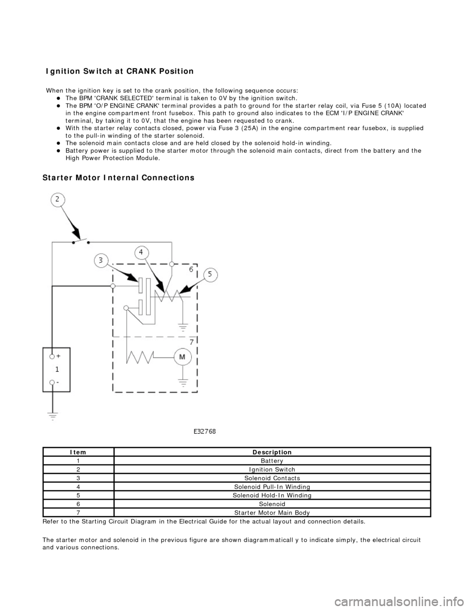
Starter
Motor Internal Connections
Re
fer to the Starting Circuit Diagram in the Electrical
Guide for the actual layout and connection details.
The starter motor and solenoid in the previous figure are shown diagrammaticall y to indicate simply, the electrical circuit
and various connections.
It
em
De
scription
1Batt
ery
2Ignition Switch
3So
lenoid Contacts
4So
lenoid Pull-In Winding
5So
lenoid Hold-In Winding
6So
lenoid
7St
arter Motor Main Body
I
gnition Switch at CRANK Position
W
hen the ignition key is set to the crank position, the following sequence occurs: