battery location JAGUAR X308 1998 2.G Workshop Manual
[x] Cancel search | Manufacturer: JAGUAR, Model Year: 1998, Model line: X308, Model: JAGUAR X308 1998 2.GPages: 2490, PDF Size: 69.81 MB
Page 39 of 2490
Before inspecting a component for wear or per
forming a dimensional check,
ensure that it is absolutely clean; a slight smear
of grease can conceal an incipient failure. When a component is to be checked dimensionally against figures quoted for it,
use the correct equipment (surface plates, micrometers, dial gauges etc.) in serviceable condition. The use of makeshift
equipment can be dangerous. Reject a component if its dimensio ns are outside the limits quoted, or if damage is apparent.
A part may be refitted if its critical di mension is exactly to the limit size and it is otherwise satisfactory. Use Plastigauge 12
Type PG-1 for checking bearing surface clearance, e.g. big end bearing shell to crank jour nal. Instructions for the use of
Plastigauge and a scale giving bearing clearances in steps of 0.0025 mm (0.0001 in) are supplied with the package.
Safety
Precautions
• WAR
NINGS:
WORKING ON THE FUEL SYSTEM RESULTS IN FUEL AND FUEL VAPOUR BEING PRESENT IN THE ATMOSPHERE. FUEL
VAPOUR IS EXTREMELY FLAMMABLE, HENCE GREAT CARE MUST BE TAKEN WHILST WORKING ON THE FUEL SYSTEM.
ADHERE STRICTLY TO THE FOLLOWING PRECAUTIONS:
DO
NOT SMOKE IN THE WORK AREA.
DISP
LAY 'NO SMOKING' SIGNS AROUND THE AREA.
DISCONNECT TH
E BATTERY BEFORE WORKING ON THE FUEL SYSTEM.
DO NOT CONNEC
T/DISCONNECT ELECTRICAL CIRCUITS
, USE ELECTRICAL EQUIPMENT OR OTHER TOOLS OR
ENGAGE IN WORKING PRACTICES WHICH IN ANY WAY MAY RESULT IN THE PRODUCTION OF SPARKS.
ENS
URE THAT A CO2 FIRE EXTINGUISHER IS CLOSE AT HAND.
ENS
URE THAT DRY SAND IS AVAILABLE TO SOAK UP ANY FUEL SPILLAGE.
EMP
TY FUEL USING SUITABLE FIRE PROOF EQUIPMENT IN
TO AN AUTHORIZED EXPLOSION PROOF CONTAINER.
DO NOT EMP
TY FUEL WHILE WORKING IN A WORKSHOP OR A PIT.
ENS
URE THAT WORKING AREA IS WELL VENTILATED.
ENS
URE THAT ANY WORK ON THE FUEL SYSTEM IS ON
LY CARRIED OUT BY EXPERIENCED AND WELL QUALIFIED
MAINTENANCE PERSONNEL.
ENS
URE THAT FUME EXTRACTION EQUIPMENT IS USED WHERE APPROPRIATE.
FUME EXTRACTION EQUIPMENT MUST BE IN OPERATION WHEN SOLVENTS ARE USED E.G. TRICHLOROETHANE,
WHITE SPIRIT, SBP3, METHYLENE CHLORIDE, PERCHLORETHY LENE. DO NOT SMOKE IN THE VICINITY OF VOLATILE
DEGREASING AGENTS.
General workshop practices:
Disc
onnect the grounded termin
al of the vehicle battery.
D
o not apply heat in an attempt to free seized nuts or fitt
ings; as well as causing damage to protective coatings,
there is a risk of damage from stray heat to electronic equipment and brake lines.
Keep oils and solven
ts away from naked flames and other sour
ces of ignition.
Adhere str
ictly to handling and safety inst
ructions given on containers and labels.
E
nsure that a suitab
le form of fire extinguisher is conveniently located.
Wh
en using electrical tools and equipment, inspect the power
lead for damage and check that it is properly earthed.
D
o not leave tools, equipment, spilt oil etc. around the work area.
Working beneath a vehicle:
Wh
enever possible, use a ramp or
pit in preference to jacking.
Posit
ion chocks at the wheels as we
ll as applying the parking brake.
N
ever rely on a jack alone to support a
vehicle; use axle stands, or blocks care fully placed at the jacking points, to
provide a rigid location.
Ch
eck that any lifting equipment used has adeq
uate capacity and is fully serviceable.
Working on air conditioning systems:
D
o not disconnect any pipes of the refrigeration system
unless you are trained and instructed to do so; a refrigerant
is used which can cause blindness if allowed to come into contact with the eyes.
Health Protection
P
rolonged and repeated contact with mineral oil will result in the removal of natural oils from the skin, leading to dryness,
In
spection
Page 661 of 2490

2. Fit the camshaft caps to their respective locations (5 to 9 from the front) and in the correct orientation
(arrow to front of engine).
3. Fit and tighten the cap securing bolts. Tighten evenly,
in stages, to 9 - 11 Nm.
3. Fit the camshaft locking tool 303 - 530 (fitted for following
operation) align the camshaft as necessary.
4. Refit Exhaust Camshaft Sprocket . Refer to Operation 12.65.74.
5. With the camshaft (303 - 530) and crankshaft (303 - 531)
setting tools removed, after the previous operation, adjust the
valve clearances on the exhaus t camshaft. refer to Operation
12.29.48.
6. Move the engine compartment co ver from the service position
and connect the gas struts.
7. Remove the paint protection sheets and close the cover.
8. Connect the battery and fit the battery cover.
Refer to the Battery Reconnection Procedure 86.15.15.
Page 663 of 2490

2. Fit the camshaft caps to their respective locations (5 to 9 from the front) and in the correct orientation
(arrow to front of engine).
3. Fit and tighten the cap securing bolts. Tighten evenly,
in stages, to 9 - 11 Nm.
3. Fit the camshaft locking tool 303 - 530 (fitted for following
operation) align the camshaft as necessary.
4. Refit Exhaust Camshaft Sprocket . Refer to Operation 12.65.73.
5. With the camshaft (303 - 530) and crankshaft (303 - 531)
setting tools removed, after the previous operation, adjust the
valve clearances on the exhaus t camshaft. refer to Operation
12.29.48.
6. Move the engine compartment co ver from the service position
and connect the gas struts.
7. Remove the paint protection sheets and close the cover.
8. Connect the battery and fit the battery cover.
Refer to the Battery Reconnection Procedure 86.15.15.
Page 701 of 2490

1. Fit the camshaft to position in the cylinder head, with the timing flats uppermost.
2. Fit the camshaft caps to their respective locations (0 to 4 from the front) and in the correct orientation
(arrow to front of engine).
3. Fit and tighten the cap securing bolts. Tighten evenly,
in stages, to 9 - 11 Nm.
3. Fit the camshaft locking tool 303 - 530 (fitted for following
operation) align the camshaft as necessary.
4. Refit the VVT Unit to the A-Bank. Refer to Operation 12.65.71.
This also includes the VVT Bu sh Carrier Assembly, Primary
Chain and Tensioner.
5. With the camshaft (303 - 530) and crankshaft (303 - 531)
setting tools removed, after the previous operation, adjust the
valve clearances on the inlet camshaft. refer to Operation
12.29.48.
6. Refit the Timing Cover. Re fer to Operation 12.65.01.
7. Move the engine compartment co ver from the service position
and connect the gas struts.
8. Remove the paint protection sheets and close the cover.
9. Connect the battery and fit the battery cover.
Refer to the Battery Reconnection Procedure 86.15.15.
Page 703 of 2490

1.
Fit the camshaft to position in the cylinder head, with
the timing flats uppermost.
2. Fit the camshaft caps to their respective locations (0 to 4 from the front) and in the correct orientation
(arrow to front of engine).
3. Fit and tighten the cap securing bolts. Tighten evenly,
in stages, to 9 - 11 Nm.
3. Fit the camshaft locking tool 303 - 530 (fitted for following
operation) align the camshaft as necessary.
4. Refit the VVT Unit to the A-Bank. Refer to Operation 12.65.70.
This also includes the VVT Bu sh Carrier Assembly, Primary
Chain and Tensioner.
5. With the camshaft (303 - 530) and crankshaft (303 - 531)
setting tools removed, after the previous operation, adjust the
valve clearances on the inlet camshaft. refer to Operation
12.29.48.
6. Refit the Timing Cover. Re fer to Operation 12.65.01.
7. Move the engine compartment co ver from the service position
and connect the gas struts.
8. Remove the paint protection sheets and close the cover.
9. Connect the battery and fit the battery cover.
Re
fer to the Battery Reconnection Procedure 86.15.15.
Page 923 of 2490
be 'hun
g up' within the engine because it is not up to operating
temperature.
Should the oil level subsequently be topped-up, the level could
become too high, causing oil burning.
Typically, 0.875L is hung up.
Refill the engine with the correct specification engine oil.
58. Refill the automatic transmission. Refer to Section 307-01A,
Operation 44.24. 02.
59. Refill and bleed the power stee ring system. Refer to Section
211-02 General Procedures.
60. Repressurise the air conditioni ng system. Refer to Operation
82.30.30 and note all Wa rnings and Cautions.
61
.
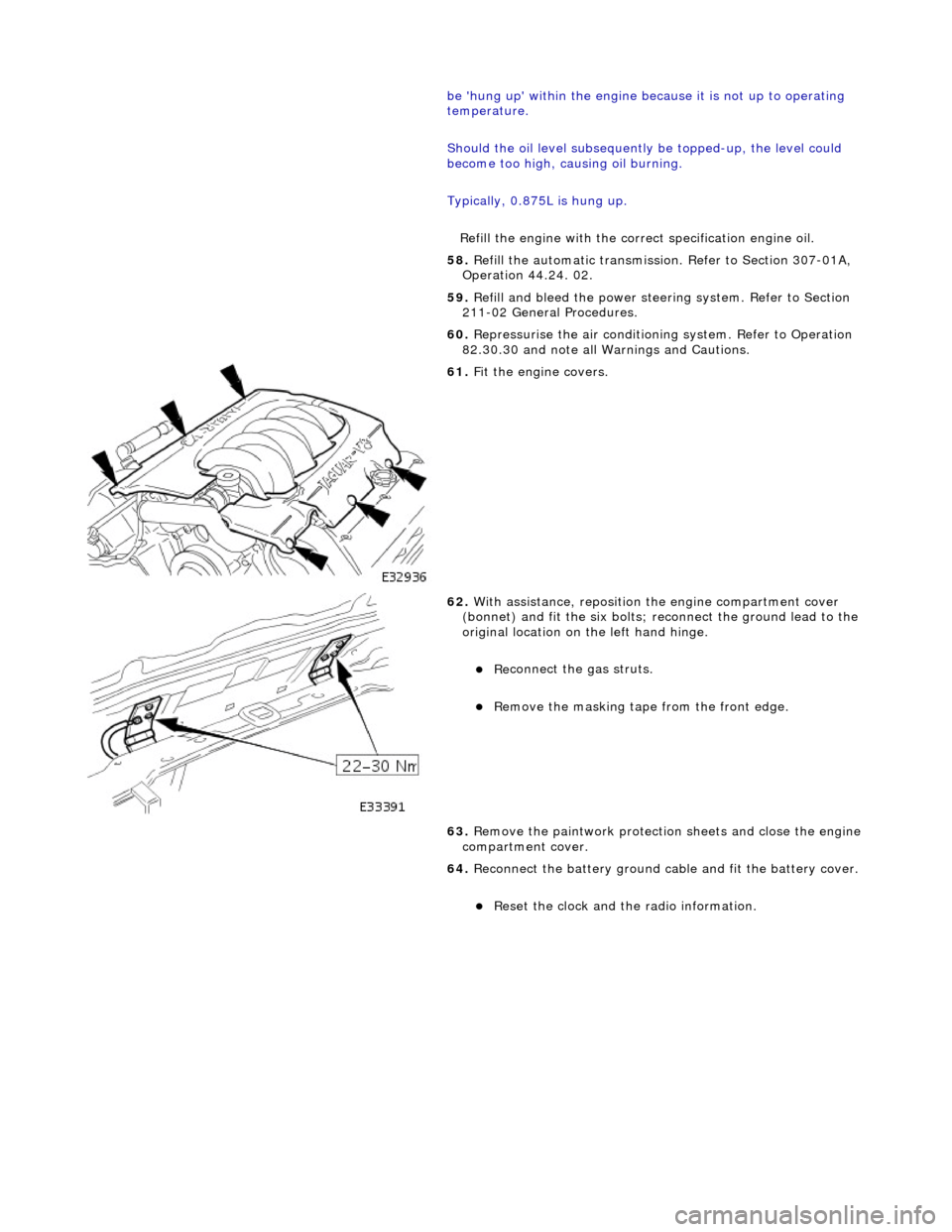
Fit the engine covers.
62
.
With assistance, reposition the engine compartment cover
(bonnet) and fit the si x bolts; reconnect the ground lead to the
original location on the left hand hinge.
Re
connect the gas struts.
R
emove the masking tape from the front edge.
63. Remove the paintwork protection sheets and close the engine
compartment cover.
64. Reconnect the battery ground cable and fit the battery cover.
Re
set the clock and the radio information.
Page 1241 of 2490
E
lectronic Engine Controls - Engine
Control Module (ECM) Adaptation
Gen
eral Procedures
When to car
ry out adaptations
DTCs P1000/P1111 Conditions for adaptation
Fuelling Adaptations Drive Cycle
•
NOTE: Make sure the engine is at normal operating
temperature. (75°C, 167°F) 1.
Whenever the battery is disconnected, the Engine Control
Module (ECM) adaptations are reset to a "green" ECM
condition. In this condition, certain functions of the ECM are
inhibited, and the ECM must "r elearn" these functions. To
enable the ECM to do this, the vehicle will have to perform
some maneuvres which it may, or may not, do during a normal
road test. The routine in this pr ocedure should be carried out at
Pre-Delivery Inspection, and after any emissions related
rectification work involving the disconnection of the battery.
2. When the DTCs relating to a rectified concern are cleared,
P1000 (system checks not complete since last memory clear)
will be flagged. This DTC does no t indicate a failure, just that
diagnostic drive cycles need to be performed. The vehicle's on-
board diagnostic system will confirm that all the diagnostic
drive cycles are complete by flagging P1111, (system checks
complete since last memory clear)
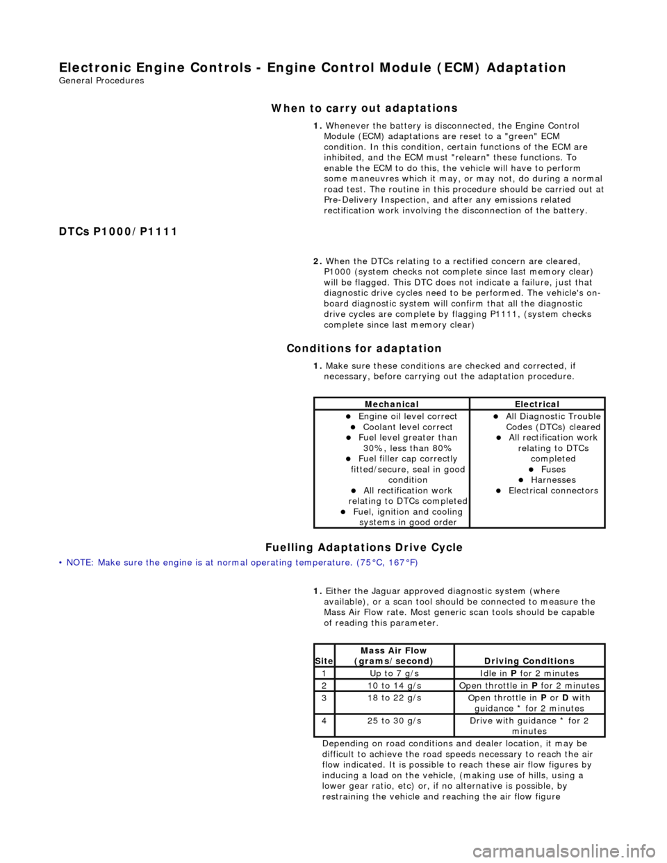
1. Make sure these conditions are checked and corrected, if
necessary, before carrying ou t the adaptation procedure.
MechanicalElectrical
Engi
ne oil level correct
Coo
lant level correct
F
uel level greater than
30%, less than 80%
F
uel filler cap correctly
fitted/secure, seal in good condition
Al
l rectification work
relating to DTCs completed
F
uel, ignition and cooling
systems in good order
Al
l Diagnostic Trouble
Codes (DTCs) cleared
Al
l rectification work
relating to DTCs completed
F
uses
Harnes
ses
E
lectrical connectors
1.
Either
the Jaguar approved diagnostic system (where
available), or a scan tool should be connected to measure the
Mass Air Flow rate. Most generi c scan tools should be capable
of reading this parameter.
Depending on road conditions and dealer location, it may be
difficult to achieve the road sp eeds necessary to reach the air
flow indicated. It is possible to reach these air flow figures by
inducing a load on the vehicle, (making use of hills, using a
lower gear ratio, etc) or, if no alternative is possible, by
restraining the vehicle and re aching the air flow figure
Si
te
Mass Air Flow
(gra
ms/second)
D
riving Conditions
1Up t
o 7 g/s
Idle
in
P for 2 minutes
21
0 to 14 g/s
O
pen throttle in
P for 2 minutes
31
8 to 22 g/s
O
pen throttle in
P or D with
guidance * for 2 minutes
42
5 to 30 g/s
D
rive with guidance * for 2
minutes
Page 1440 of 2490

Automatic Transmission/Transaxle - 4.0L SC V8 - AJ26 - Transmission
Fluid Filter
In-vehicle Repair
Installation
1.
Disconnect the battery ground lead.
2. Raise the vehicle for access.
3. Remove the fluid pan, refer to Operation 44.24.04.
4. Remove the fluid filter.
Pull the filter squarely to disengage the pick-up 'O' ring
and location tang - there is NO mechanical retention.
1. Installation is the reverse of the removal procedure noting
that:
2. Renew the 'O' ring.
3. Refer to Operation 44.24.02 for fluid fill procedure.
4. Check for leaks and remove spilt fluid.
Page 1858 of 2490
In
stallation
8.
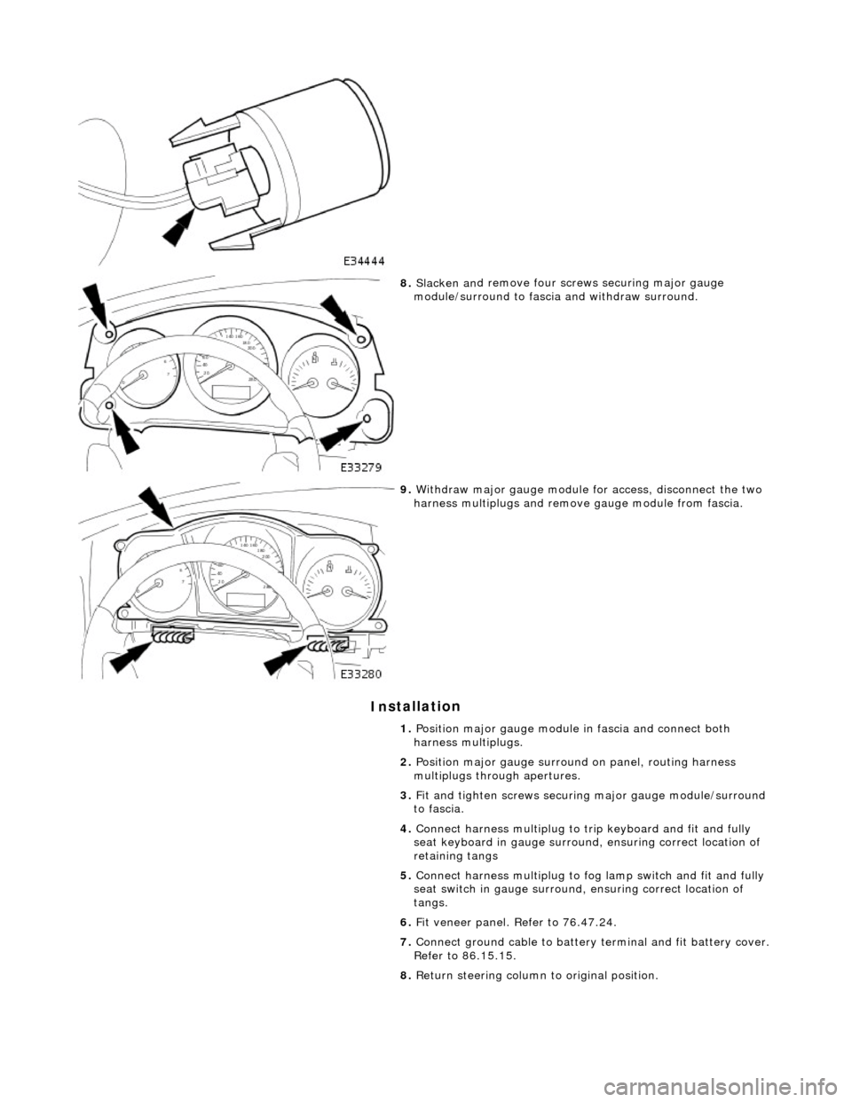
Slac ken an
d remove four screws securing major gauge
module/surround to fascia and withdraw surround.
9. With draw major gau
ge module fo
r access, disconnect the two
harness multiplugs and remove gauge module from fascia.
1. Position major gauge module in fascia and connect both
harness multiplugs.
2. Position major gauge surround on panel, routing harness
multiplugs through apertures.
3. Fit and tighten screws securing major gauge module/surround
to fascia.
4. Connect harness multiplug to tr ip keyboard and fit and fully
seat keyboard in gauge surround, ensuring correct location of
retaining tangs
5. Connect harness multiplug to fog lamp switch and fit and fully
seat switch in gaug e surround, ensuring correct location of
tangs.
6. Fit veneer panel. Refer to 76.47.24.
7. Connect ground cable to battery terminal and fit battery cover.
Refer to 86.15.15.
8. Return steering column to original position.
Page 2038 of 2490
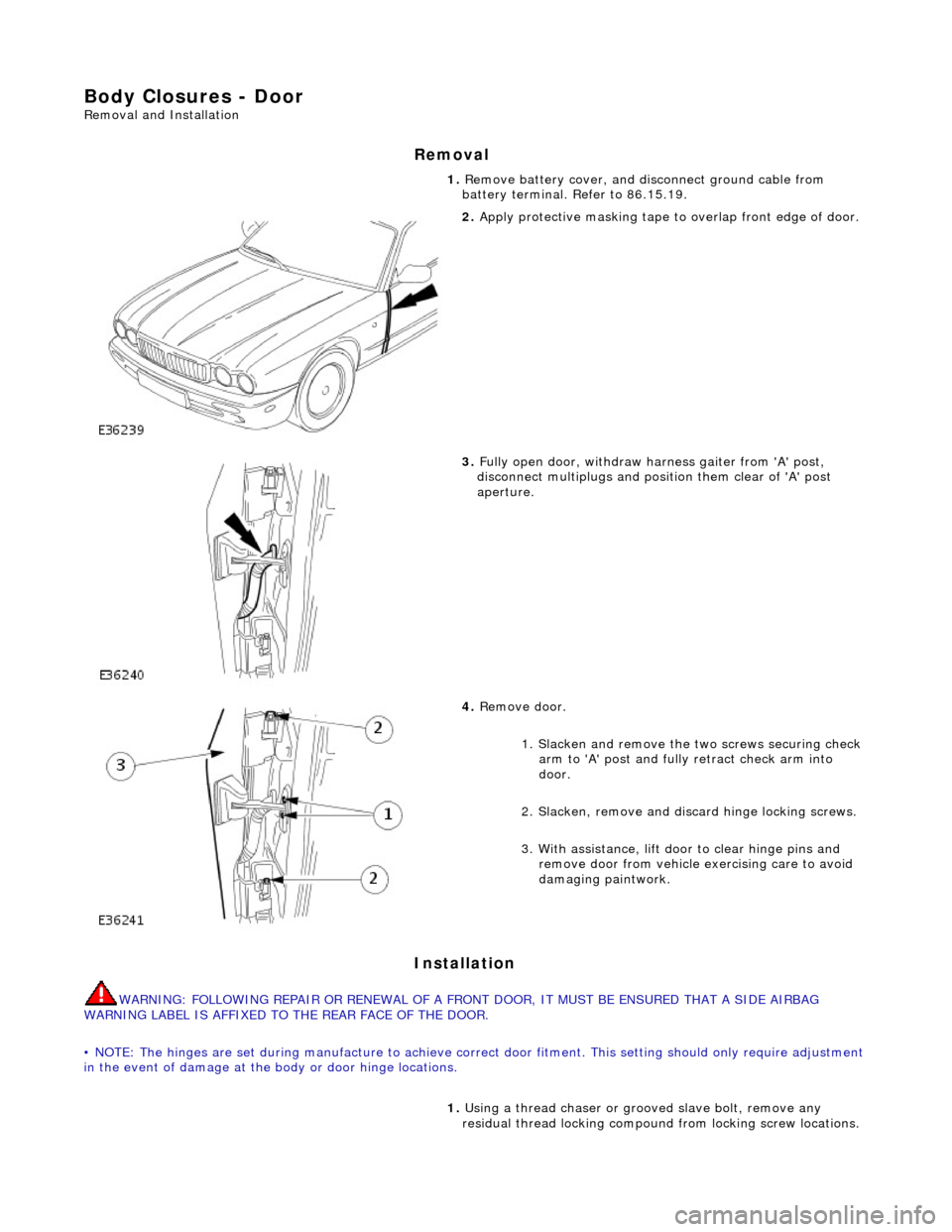
Body Closures - Door
Removal and Installation
Removal
Installation
WARNING: FOLLOWING REPAIR OR RENEWAL OF A FRONT DOOR, IT MUST BE ENSURED THAT A SIDE AIRBAG
WARNING LABEL IS AFFIXED TO THE REAR FACE OF THE DOOR.
• NOTE: The hinges are set during manufacture to achieve correct door fitment. This setting should on ly require adjustment
in the event of damage at the body or door hinge locations. 1.
Remove battery cover, and di sconnect ground cable from
battery terminal. Refer to 86.15.19.
2. Apply protective masking tape to overlap front edge of door.
3. Fully open door, withdraw harness gaiter from 'A' post,
disconnect multiplugs and posi tion them clear of 'A' post
aperture.
4. Remove door.
1. Slacken and remove the two screws securing check
arm to 'A' post and fully retract check arm into
door.
2. Slacken, remove and di scard hinge locking screws.
3. With assistance, lift d oor to clear hinge pins and
remove door from vehicle exercising care to avoid
damaging paintwork.
1. Using a thread chaser or gr ooved slave bolt, remove any
residual thread locking compound from locking screw locations.