antenna JAGUAR X308 1998 2.G Workshop Manual
[x] Cancel search | Manufacturer: JAGUAR, Model Year: 1998, Model line: X308, Model: JAGUAR X308 1998 2.GPages: 2490, PDF Size: 69.81 MB
Page 24 of 2490

В
В В В В В В В В В В В В В
В В В В В В В В В 414‐02: В Generator В and В Regulator В
В В В В В В В В В В В В В В В В Descriptio nВ and В Operati
on
В
В В В В В В В В В В В В В В В В В В В В GeneratorВ
В В В В В В В В В В В В В В В В Diagnosis В and В Testing В
В В В В В В В В В В В В В В В В В В В В GeneratorВ
В В В В В В В В В В В В В В В В RemovalВ and В Installation В
В В В В В В В В В В В В В В В В В В В В GeneratorВ (86.10.02)  ‐ 3.2L В NA В V8  ‐ AJ26/4.0L В NA В V8  ‐ AJ27 В
В В В В В В В В В В В В В В В В В В В В GeneratorВ (86.10.02)  ‐ 4.0L В SCВ V8 ‐ AJ26 В
В В В В В В В В В В В В В В В В В В В В VoltageВ Regulator В (86.10.28) В
В
В В В В В В В В 415: В Information В and В Entertainment В Systems В
В
В В В В В В В В В В В В 415‐01: В Audio В Unit В
В В В В В В В В В В В В В В В В Description В and В Operati
onВ
В В В В В В В В В В В В В В В В В В В В AudioВ System В
В В В В В В В В В В В В В В В В Diagnosis В and В Testing В
В В В В В В В В В В В В В В В В В В В В AudioВ System В
В В В В В В В В В В В В В В В В RemovalВ and В Installation В
В В В В В В В В В В В В В В В В В В В В CapacitorВ (86.10.33) В
В
В В В В В В В В В В В В 415‐02: В Antenna В
В В В В В В В В В В В В В В В В Description В and В Operation В
В В В В В В В В В В В В В В В В В В В В AntennaВ
В В В В В В В В В В В В В В В В Diagnosis В and В Testing В
В В В В В В В В В В В В В В В В В В В В AntennaВ
В
В В В В В В В В В В В В 415‐03: В Speakers В
В В В В В В В В В В В В В В В В Description В and В Operation В
В В В В В В В В В В В В В В В В В В В В SpeakersВ
В В В В В В В В В В В В В В В В Diagnosis В and В Testing В
В В В В В В В В В В В В В В В В В В В В SpeakersВ
В В В В В В В В В В В В В В В В RemovalВ and В Installation В
                    A‐Pillar T
weeter В Speaker В LH В
В В В В В В В В В В В В В В В В В В В В A‐PillarВ Tweeter В Speaker В RH В (86.50.65) В
В В В В В В В В В В В В В В В В В В В В DoorВ Speaker В (86.50.13) В
Page 1906 of 2490
Audio Unit - Audio System
Diagnosis and Testing
Tests Using the Portable Diagnostic Unit
Refer to PDU User Guide
The PDU is unable to diagnose radio head, CD autochanger or amplifier faults; there are no self-diagnostics associated with
these components.
PDU is able to test the speakers and the antenna, along with associated wiring and connections, therefore by a process of
elimination, the other components can be diagnosed.
Page 1908 of 2490
Antenna - Antenna
Description and Operation
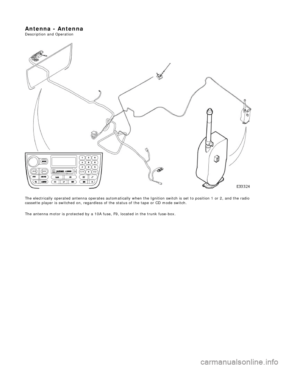
The electrically operated antenna operates automatically when the Ignition switch is set to position 1 or 2, and the radio
cassette player is switched on , regardless of the status of the tape or CD mode switch.
The antenna motor is protected by a 10A fuse, F9, located in the trunk fuse-box.
Page 1909 of 2490

Antenna - Antenna
Diagnosis and Testing
Tests Using the Portable Diagnostic Unit
Refer to PDU User Guide
The PDU tests whether or not the antenna raises and lowers correctly. Although it is obvious if the antenna is not operating,
the PDU analyses why it is not operating an d indicates problems such as a faulty radio head signal output, faulty wiring, loss of power due to a blown fuse.
Page 1978 of 2490
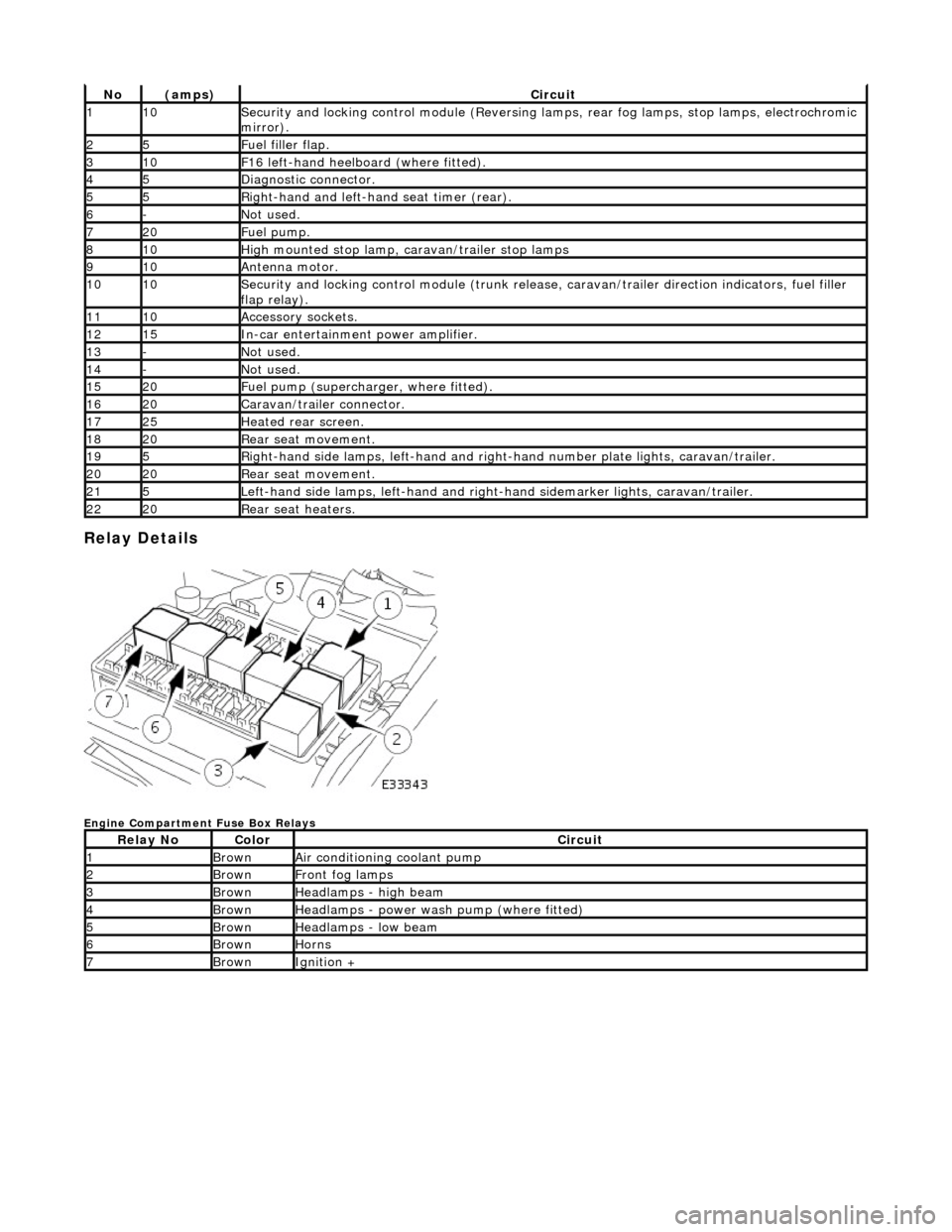
Relay Details
Engine Compartment Fuse Box Relays
No(amps)Circuit
110Security and locking control module (Reversing lamps, rear fog lamps, stop lamps, electrochromic
mirror).
25Fuel filler flap.
310F16 left-hand heelboard (where fitted).
45Diagnostic connector.
55Right-hand and left-han d seat timer (rear).
6-Not used.
720Fuel pump.
810High mounted stop lamp, caravan/trailer stop lamps
910Antenna motor.
1010Security and locking control module (trunk release, caravan/trailer direction indicators, fuel filler
flap relay).
1110Accessory sockets.
1215In-car entertainment power amplifier.
13-Not used.
14-Not used.
1520Fuel pump (supercharger, where fitted).
1620Caravan/trailer connector.
1725Heated rear screen.
1820Rear seat movement.
195Right-hand side lamps, left-h and and right-hand number pl ate lights, caravan/trailer.
2020Rear seat movement.
215Left-hand side lamps, left-hand and right-hand sidemarker lights, caravan/trailer.
2220Rear seat heaters.
Relay NoColorCircuit
1BrownAir conditioning coolant pump
2BrownFront fog lamps
3BrownHeadlamps - high beam
4BrownHeadlamps - power wash pump (where fitted)
5BrownHeadlamps - low beam
6BrownHorns
7BrownIgnition +
Page 2210 of 2490
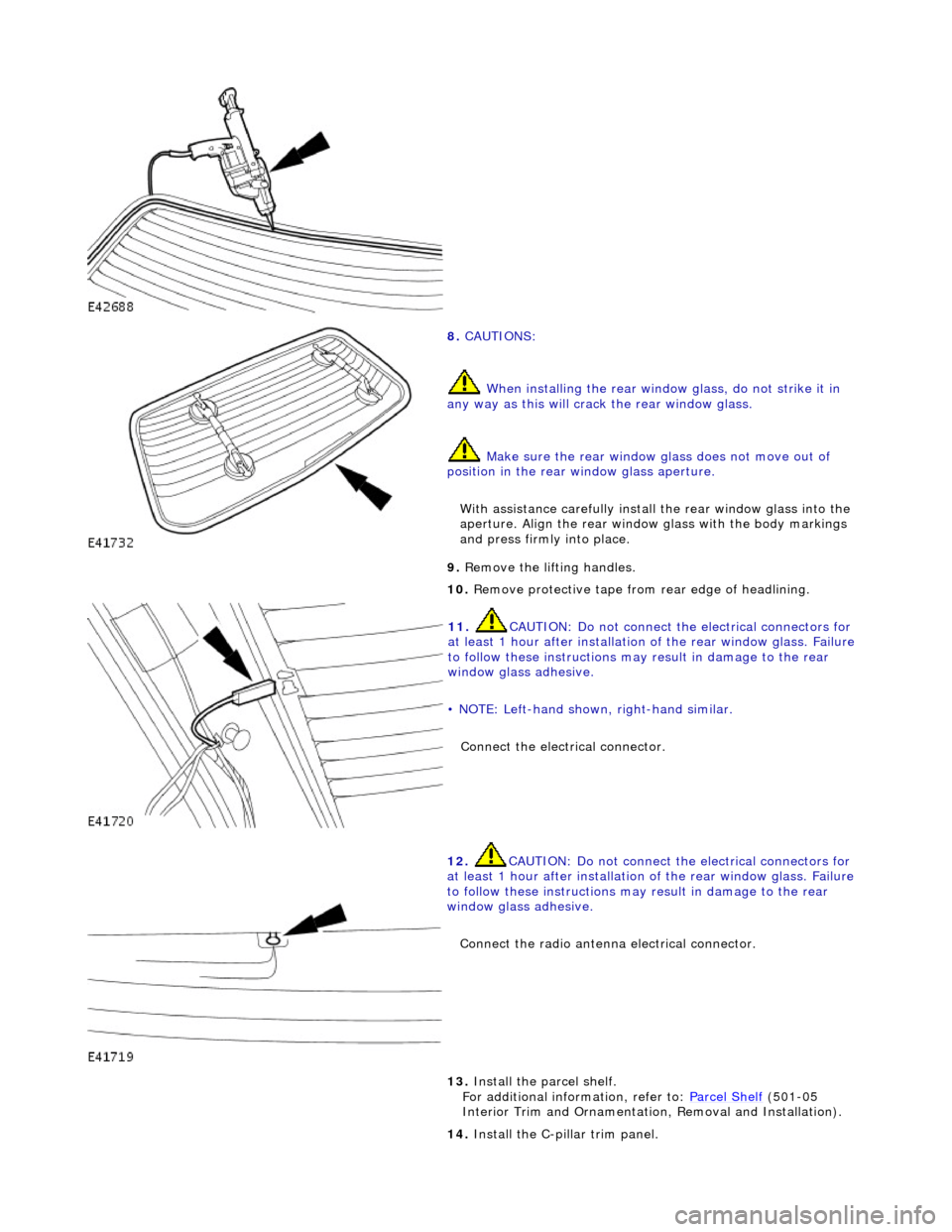
8. CAUTIONS:
When installing the rear window glass, do not strike it in
any way as this will crac k the rear window glass.
Make sure the rear window glass does not move out of
position in the rear window glass aperture.
With assistance carefully install the rear window glass into the
aperture. Align the rear window glass with the body markings
and press firmly into place.
9. Remove the lifting handles.
10. Remove protective tape from rear edge of headlining.
11. CAUTION: Do not connect the electrical connectors for
at least 1 hour after installation of the rear window glass. Failure
to follow these instructions may result in damage to the rear
window glass adhesive.
• NOTE: Left-hand shown, right-hand similar.
Connect the electrical connector.
12. CAUTION: Do not connect the electrical connectors for
at least 1 hour after installation of the rear window glass. Failure
to follow these instructions may result in damage to the rear
window glass adhesive.
Connect the radio antenna electrical connector.
13. Install the parcel shelf.
For additional information, refer to: Parcel Shelf (501-05
Interior Trim and Ornamentatio n, Removal and Installation).
14. Install the C-pillar trim panel.