brake fluid JAGUAR X308 1998 2.G Workshop Manual
[x] Cancel search | Manufacturer: JAGUAR, Model Year: 1998, Model line: X308, Model: JAGUAR X308 1998 2.GPages: 2490, PDF Size: 69.81 MB
Page 6 of 2490

Brake Pads (70.40.02) ‐ Vehicles With:
High Performance Brakes
206‐04: Rear Disc Brake
Specification
Description and Operation
Rear Disc Brake
Removal and Installation
Brake Caliper (70.55.03) (70.55.25) ‐ Vehicles With: Standard Brakes
Brake Caliper (70.55.03) (70.55.25) ‐ Vehicles With: High Performance Brakes
Brake Disc (70.10.11) ‐ Vehicles With: Standard Brakes
Brake Dis
c (70.10.11) ‐ Vehicles With: High Performance Brakes
Brake Pads (70.40.03) ‐ Vehicles With: Standard Brakes
Brake Pads (70.40.03) ‐ Vehicles With: High Performance Brakes
206‐05: Parking Brake and Actuation
Specification
Description and Operation
Parking Brake
General Procedures
Parking Brake Cable Adjustment (70.35.10)
Parking Brake Shoe and Li
ning Adjustment (70.35.37)
Removal and Installation
Parking Brake Control (70.35.08)
Parking Brake Control Shroud (76.13.63)
Parking Brake Shoes (70.40.05)
Parking Brake Warning Indicator Switch (86.65.45)
206‐06: Hydraulic Brake Actuation
Specification
Description and Operation
Hydraulic Brake Actuation
Removal and Installation
Brake Fluid Reservoir (70.30.16)
Brake Master Cylinder (70.30.
08)
Brake Pedal and Bracket (70.35.03)
Brake Pedal and Bracket, Brake Booster and Brake Master Cylinder (70.35.39)
Page 38 of 2490
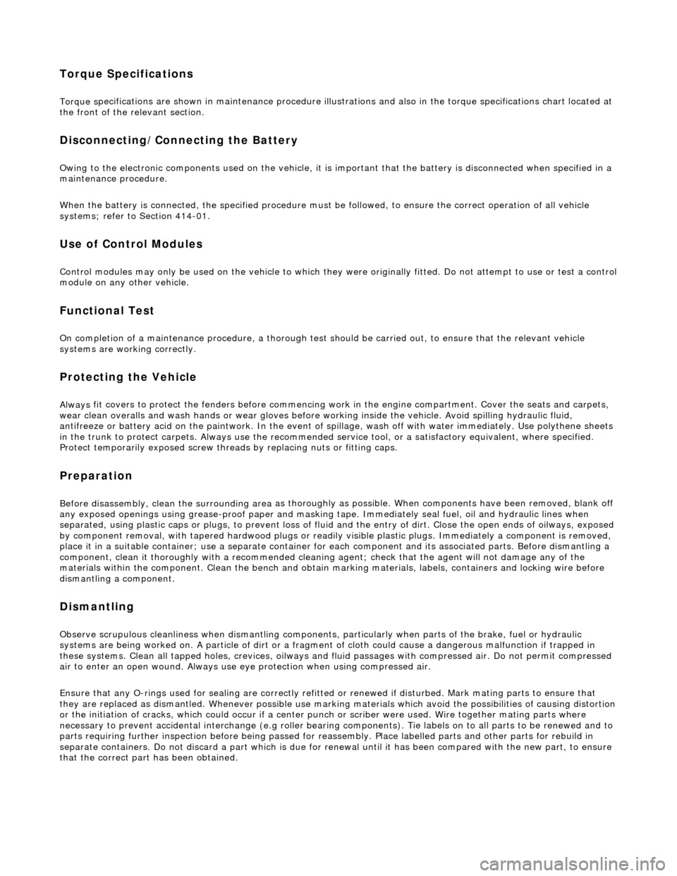
Torque Specifications
Torque sp
ecifications are shown in maintenance procedure illustra
tions and also in the torque specifications chart located at
the front of the relevant section.
Disconnecting/Connecting the Battery
Ow ing t
o the electronic components used on the vehicle, it is important that the battery is disconnected when specified in a
maintenance procedure.
When the battery is connected, the specified procedure must be followed, to ensure the correct operation of all vehicle
systems; refer to Section 414-01.
Use of Control Modules
Control modu les may
only be used on the ve
hicle to which they were originally fitted. Do not attempt to use or test a control
module on any other vehicle.
Function
al Test
On
completion of a maintenance procedure, a thorough test should be carried out, to ensu
re that the relevant vehicle
systems are working correctly.
Protecting the Vehicle
Al ways
fit covers to protect
the fenders before commencing work in the engi ne compartment. Cover the seats and carpets,
wear clean overalls and wash hands or wear gloves before working inside the vehicle. Avoid spilling hydraulic fluid,
antifreeze or battery acid on the paintwork. In the event of spillage, wash off with water imme diately. Use polythene sheets
in the trunk to protect carpets. Always use the recommended service tool, or a satisfactory equivalent, where specified.
Protect temporarily exposed screw thread s by replacing nuts or fitting caps.
Preparation
Before disassembly, clean the surrounding ar ea
as thoroughly as possible. When co
mponents have been removed, blank off
any exposed openings using grease-proof paper and masking tape. Immediately seal fuel, oil and hydraulic lines when
separated, using plastic caps or plugs, to prevent loss of fluid and the entry of dirt. Close the open ends of oilways, exposed
by component removal, with tapered hardw ood plugs or readily visible plastic plugs. Immediately a component is removed,
place it in a suitable container; use a se parate container for each component and its associated pa rts. Before dismantling a
component, clean it thoroughly with a recommended cleaning agent; check that the agent will not damage any of the
materials within the component. Clean the bench and obtain ma rking materials, labels, containers and locking wire before
dismantling a component.
Dismantling
O b
serve scrupulous cleanliness when dismantling components,
particularly when parts of the brake, fuel or hydraulic
systems are being worked on. A particle of dirt or a fragment of cloth could caus e a dangerous malfunction if trapped in
these systems. Clean all tapped holes, crev ices, oilways and fluid passages with compressed air. Do not permit compressed
air to enter an open wound. Always use ey e protection when using compressed air.
Ensure that any O-rings used for sealing are correctly refitted or renewed if disturbed. Mark mating parts to ensure that
they are replaced as dismantled. Whenever possible use markin g materials which avoid the possibilities of causing distortion
or the initiation of cracks, which could occur if a center pu nch or scriber were used. Wire together mating parts where
necessary to prevent accidental interchange (e.g roller bearing components). Tie labels on to all parts to be renewed and to
parts requiring further inspection before being passed fo r reassembly. Place labelled parts and other parts for rebuild in
separate containers. Do not disc ard a part which is due for renewal until it ha s been compared with the new part, to ensure
that the correct part has been obtained.
Page 42 of 2490
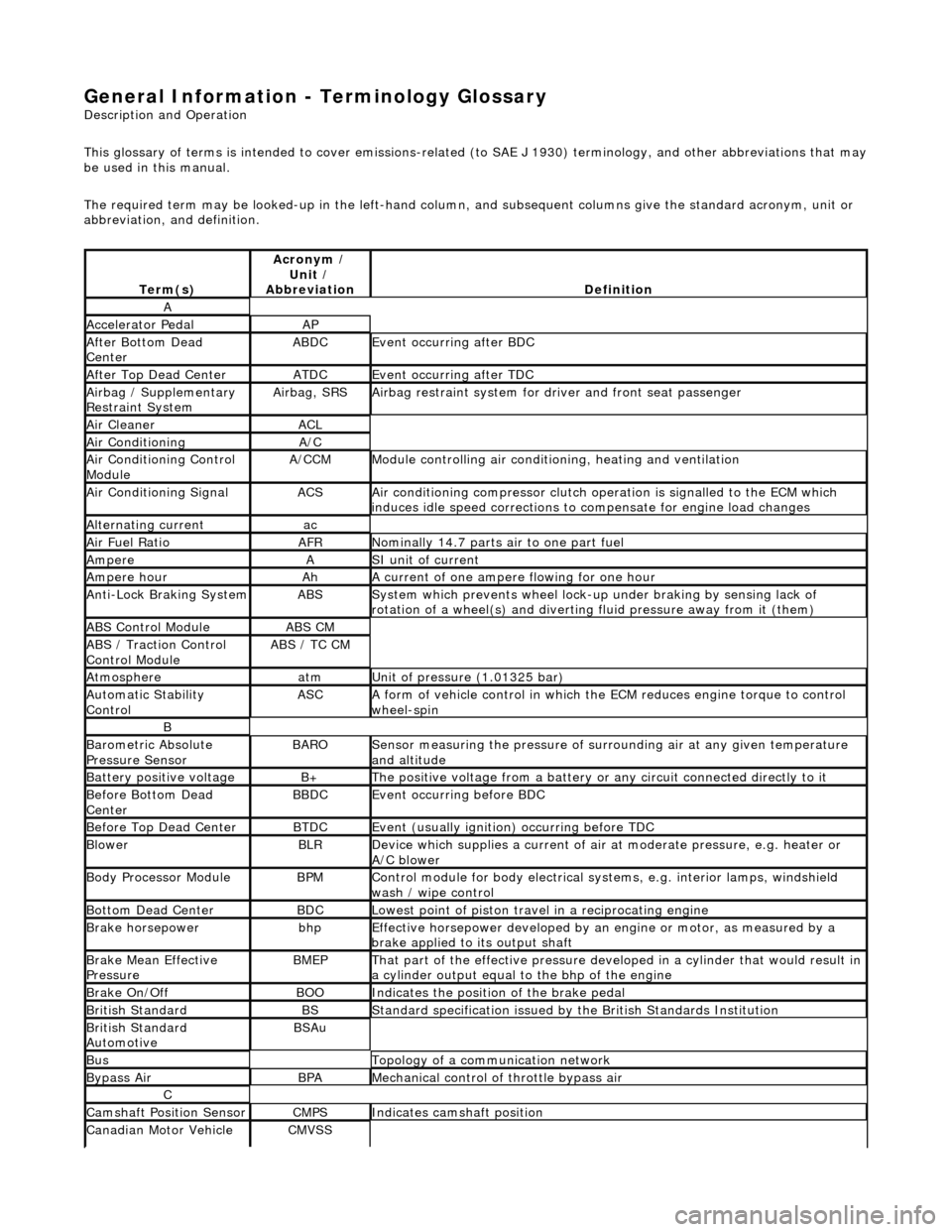
General Information - Terminology Glossary
Description an
d Operation
This glossary of terms is intended to cover emissions-related (to SAE J 1930) term inology, and other abbreviations that may
be used in this manual.
The required term may be looked-up in th e left-hand column, and subsequent columns give the standard acronym, unit or
abbreviation, and definition.
Te rm
(s)
Acr
ony
m /
Unit /
Abbreviation
De fi
nition
A
Accel
e
rator Pedal
AP
Af
ter Botto
m Dead
Center
ABDCEvent occurri ng after
BDC
Af
ter Top Dead CenterATDCEvent occurri ng after
TDC
Ai
rbag /
Supplementary
Restraint System
Airbag, SRSAi rbag restraint system for
dr
iver and front seat passenger
Air Cleane rACL
Air ConditioningA/C
Air Conditioning Con t
rol
Module
A/CCMModule c
ontrolling air conditioning, heating and ventilation
Air Conditioning SignalACSA
i
r conditioning compressor clutch operation is signalled to the ECM which
induces idle speed corrections to co mpensate for engine load changes
Alternating cu
rrent
ac
Ai
r Fuel R
atio
AFRN
omi
nally 14.7 parts air to one part fuel
Ampe
reASI unit of current
Ampere hourAhA current of one ampere
fl
owing for one hour
Anti-Lock Braking SystemABSS
y
stem which prevents wheel lock-up
under braking by sensing lack of
rotation of a wheel(s) and divertin g fluid pressure away from it (them)
ABS Control Mo
dule
ABS CM
ABS /
T
raction Control
Control Module
ABS / T
C CM
Atmosph
e
re
atmU
n
it of pressure (1.01325 bar)
Au
to
matic Stability
Control
ASCA form of vehicle
control
in which the ECM reduces en gine torque to control
wheel-spin
B
Baro me
tric Absolute
Pressure Sensor
BAR OSensor measuring the pressure of surr ou
nding air at any given temperature
and altitude
Bat t
ery positive voltage
B+The posi
ti
ve voltage from a battery or
any circuit connected directly to it
Before Bottom Dead
CenterBBDCEvent occurri ng before BD
C
Before Top Dead
Center
BTD
CEvent (usual ly
ignition) occurring before TDC
Blowe
rBLRDe
vice which supplies a current of air at
moderate pressure, e.g. heater or
A/C blower
Body Processor M
odule
BPMControl modu
le
for body electrical systems, e.g. interior lamps, windshield
wash / wipe control
Bott om D
ead Center
BD
CLowest poin t of piston
travel in a reciprocating engine
Brake hors
epowe
r
bhpEffecti
ve horsepower devel
oped by an
engine or motor, as measured by a
brake applied to its output shaft
Brake Mean Effective
Pres sureBME PThat p
art of the effective
pressure developed in a cyli nder that would result in
a cylinder output equal to the bhp of the engine
Brake On/ O
ff
BOOIn
dic
ates the position of the brake pedal
Br
it
ish Standard
BSStan
dar
d specification issued by the British Standards Institution
Br
it
ish Standard
Automotive
BSAu
BusTopology of a commu n
ication network
Bypass
AirBPAMechanica l
control of throttle bypass air
C
Camshaft Posit
i
on Sensor
CMPSIndi
cat
es camshaft position
Canadian Motor
V
ehicle
CMVSS
Page 67 of 2490
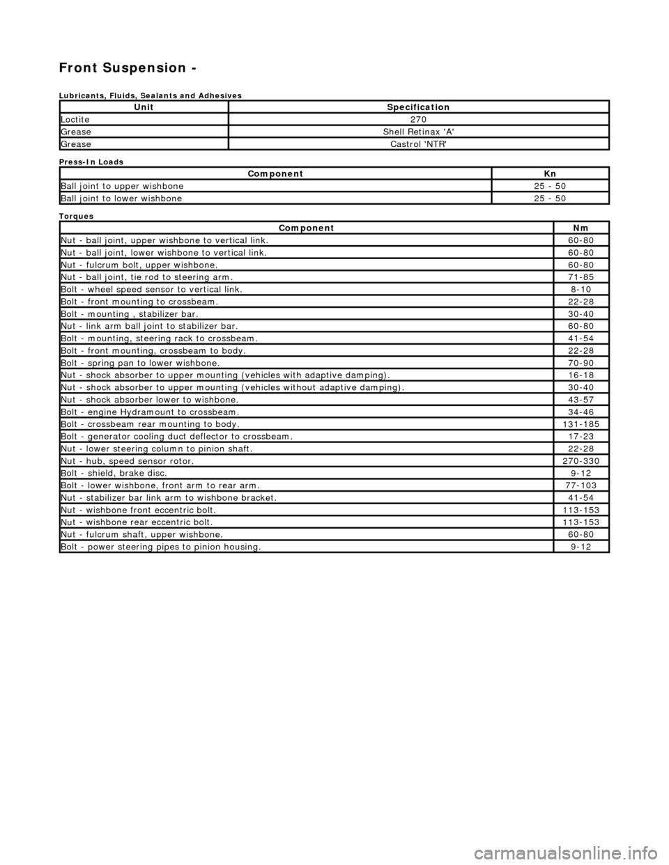
Front Suspension -
Lubri
cants, Fluids, Sealants and Adhesives
Press-In Loads
Torques
UnitS
pecification
Loctite27
0
Greas
e
Shell Retin
ax 'A'
Greas
e
Castro
l 'NTR'
Com
ponent
Kn
Ball join
t to upper wishbone
25
- 50
B
all joint to lower wishbone
25
- 50
Com
ponent
Nm
N
ut - ball joint, upper wishbone to vertical link.
60
-80
N
ut - ball joint, lower wishbone to vertical link.
60
-80
Nu
t - fulcrum bolt, upper wishbone.
60
-80
N
ut - ball joint, tie rod to steering arm.
71
-85
Bol
t - wheel speed sensor to vertical link.
8-1
0
Bol
t - front mounting to crossbeam.
22
-28
Bolt
- mounting , stabilizer bar.
30
-40
N
ut - link arm ball joint to stabilizer bar.
60
-80
Bolt
- mounting, steering rack to crossbeam.
41
-54
B
olt - front mounting, crossbeam to body.
22
-28
Bol
t - spring pan to lower wishbone.
70
-90
N
ut - shock absorber to upper mounting
(vehicles with adaptive damping).
16
-18
Nu
t - shock absorber to upper mounting (vehicles without adaptive damping).
30
-40
N
ut - shock absorber lower to wishbone.
43
-57
B
olt - engine Hydramount to crossbeam.
34
-46
B
olt - crossbeam rear mounting to body.
13
1-185
Bol
t - generator cooling du
ct deflector to crossbeam.
17
-23
N
ut - lower steering column to pinion shaft.
22
-28
N
ut - hub, speed sensor rotor.
27
0-330
B
olt - shield, brake disc.
9-1
2
Bol
t - lower wishbone, front arm to rear arm.
77
-103
Nu
t - stabilizer bar link arm to wishbone bracket.
41
-54
N
ut - wishbone front
eccentric bolt.
11
3-153
Nu
t - wishbone rear
eccentric bolt.
11
3-153
N
ut - fulcrum shaft, upper wishbone.
60
-80
Bolt -
power steering pi
pes to pinion housing.
9-1
2
Page 307 of 2490
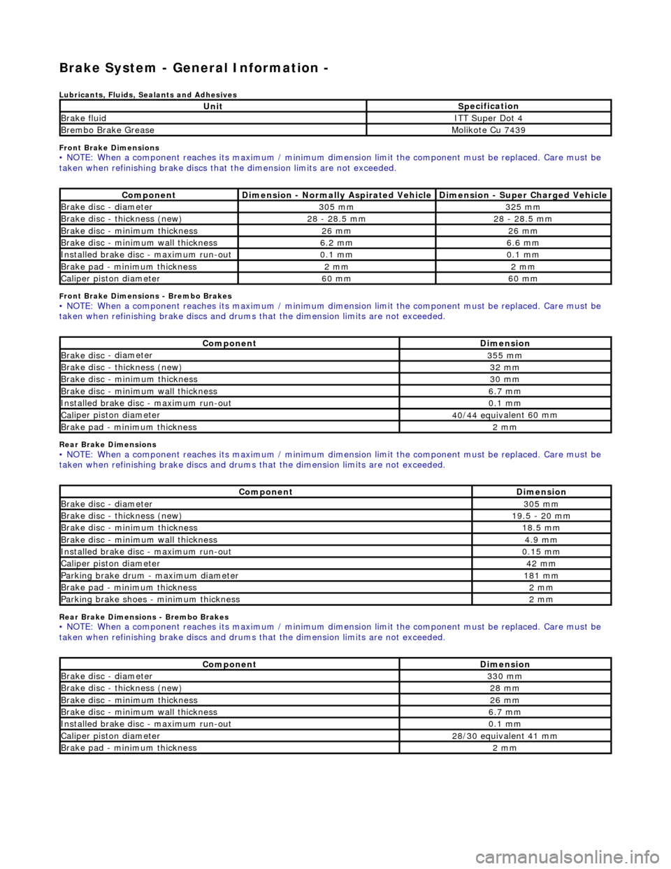
Brake S
ystem - General Information -
Lu
bricants, Fluids, Sealants and Adhesives
Front Brake Dimensions
• NO
TE: When a component reaches its maximum / minimum dimension limit the component must be replaced. Care must be
taken when refinishing brake discs that the dimension limits are not exceeded.
F
ront Brake Dimensions - Brembo Brakes
• NO
TE: When a component reaches its maximum / minimum dimension limit the component must be replaced. Care must be
taken when refinishing brake discs and drums that the dimension limits are not exceeded.
R
ear Brake Dimensions
• NO
TE: When a component reaches its maximum / minimum dimension limit the component must be replaced. Care must be
taken when refinishing brake discs and drums that the dimension limits are not exceeded.
R
ear Brake Dimensions - Brembo Brakes
• NO
TE: When a component reaches its maximum / minimum dimension limit the component must be replaced. Care must be
taken when refinishing brake discs and drums that the dimension limits are not exceeded.
UnitSp
ecification
Bra
ke fluid
IT
T Super Dot 4
Brembo Br
ake Grease
M
olikote Cu 7439
Co
mponent
Dimension - Normall
y Aspirated Vehicle
Dimension
- Super Charged Vehicle
Brake disc
- diameter
305 mm325 mm
Brake disc
- thickness (new)
28
- 28.5 mm
28 -
28.5 mm
B
rake disc - minimum thickness
26 mm26 mm
B
rake disc - minimum wall thickness
6.2 mm6.6 mm
I
nstalled brake disc - maximum run-out
0.1 mm0.1 mm
B
rake pad - minimum thickness
2 mm2 mm
Cal
iper piston diameter
60 mm60 mm
Co
mponent
Dimension
Brake disc
- diameter
355 mm
Brake disc
- thickness (new)
32 mm
B
rake disc - minimum thickness
30 mm
B
rake disc - minimum wall thickness
6.7 mm
I
nstalled brake disc - maximum run-out
0.1 mm
Cal
iper piston diameter
40/44 equiv
alent 60 mm
B
rake pad - minimum thickness
2 mm
Co
mponent
Dimension
Brake disc
- diameter
305 mm
Brake disc
- thickness (new)
19.5
- 20 mm
B
rake disc - minimum thickness
18.5 mm
B
rake disc - minimum wall thickness
4.9 mm
I
nstalled brake disc - maximum run-out
0.15 mm
Cal
iper piston diameter
42 mm
Pa
rking brake drum - maximum diameter
181 mm
B
rake pad - minimum thickness
2 mm
Pa
rking brake shoes - minimum thickness
2 mm
Co
mponent
Dimension
Brake disc
- diameter
330 mm
Brake disc
- thickness (new)
28 mm
B
rake disc - minimum thickness
26 mm
B
rake disc - minimum wall thickness
6.7 mm
I
nstalled brake disc - maximum run-out
0.1 mm
Cal
iper piston diameter
28/30 equiv
alent 41 mm
B
rake pad - minimum thickness
2 mm
Page 309 of 2490
Brake System - General Inform
ation - Brake System
D
iagnosis and Testing
Principles of Operations
The brake system operates by transferring effort applied to th e brake pedal, by the driver to the brakes at each wheel.
The braking effort is distributed to each wheel, using a hydraulic system. The system is assisted using a vacuum brake
booster that reduces pedal effort for a given hydraulic pressure. The parking brake operates on the rear wheels and is
applied using a hand operated control.
I
nspection and Verification
•
NOTE: Prior to carrying out any diagno
sis, make sure that the brake system warning indicator is functional.
Visually examine the front and rear tire and wheel assemblies for damage such as un even wear patterns, tread worn out or
sidewall damage. Verify the tires are th e same size, type and, where possible, same manufacture. Replace the damaged
wheel or excessively worn tire. For a dditional information, refer toSection 204
-0
4 Wheels and Tires
.
W
heels and tires must be cleared of an
y foreign matter and tire pressures ad justed to the correct specification.
If the tires exhibit uneven wear or feathering, the cause must be corrected. Check the steering and suspension components
for damage or wear and, if ne cessary, check and adjust front wheel alignment. For additional information, refer toSection
204
-00 Suspen
sion System
- General Informati
on
.
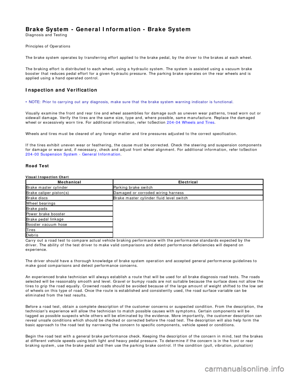
Road Test
V
isual Inspection Chart
Carr
y out a road test to compare actual vehicle braking performance with the
performance standards expected by the
driver. The ability of the test driver to make valid compar isons and detect performance deficiencies will depend on
experience.
The driver should have a thorough knowledge of brake system operation and accepted general performance guidelines to
make good comparisons and de tect performance concerns.
An experienced brake technician will always establish a route that will be used for all br ake diagnosis road tests. The roads
selected will be reasonably smooth and level. Gravel or bump y roads are not suitable because the surface does not allow the
tires to grip the road equally. Crowned roads should be avoide d because of the large amount of weight shifted to the low set
of wheels on this type of road. Once th e route is established and consistently used, the road surface variable can be
eliminated from the test results.
Before a road test, obtain a complete description of the customer concerns or suspec ted condition. From the description, the
technician's experience will allow the te chnician to match possible causes with symptoms. Certain components will be
tagged as possible suspects while others wi ll be eliminated by the evidence. More importantly, the customer description can
reveal unsafe conditions which should be ch ecked or corrected before the road test. The description will also help form the
basic approach to the road test by narrowing the concern to specific components, vehicle speed or conditions.
Begin the road test with a general brake performance check. Keeping the description of the concern in mind, test the brakes
at different vehicle speeds using both ligh t and heavy pedal pressure. To determine if the concern is in the front or rear
braking system, use the brake pe dal and then use the parking brake control. If the condition (pull, vibration, pulsation)
MechanicalElectrical
Brake m
aster cylinder
Parkin
g brake switch
Brake ca
liper piston(s)
D
amaged or corroded wiring harness
Brake di
scs
B
rake master cylinder fluid level switch
Wh
eel bearin
gs
Brake pads
Power brake booster
Brake ped
al linkage
Boost
er vacuum hose
Tire
s
De
bris
Page 310 of 2490
oc
curs only with the parking brake, th
e concern is in the rear brake system.
If the concern becomes evident during this check, verify it fits the description given before the road test. If the concern is
not evident, attempt to duplicate the condition using the information from the description.
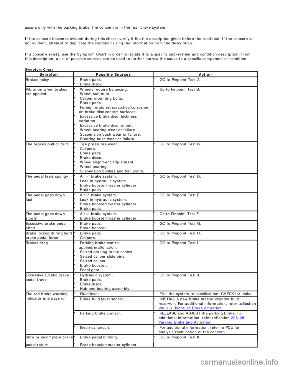
If a concern exists, use the Symptom Chart in order to isolate it to a specific sub-system and condition description. From
this description, a list of possible sources can be used to further narrow the cause to a specific component or condition.
Sym
ptom Chart
Sy
m
ptom
Possib
l
e Sources
Acti
o
n
Brakes
n
oisy
Brake pads.
Brake di
scs
.
*
*
GO to Pinpoint
Tes
t A.
*
Vibration wh
en brakes
are applied
Wh eels require bala
ncing.
Wheel hub nuts.
Caliper mounting bolts.
Brake pads.
Foreign material/scr atches/corrosion
on brake disc contact surfaces. Excessive brake disc thickness
variation. Excessive brake disc runout.
Wheel bearing wear or failure.
Suspension bush wear or failure.
Steering bush wear or failure.
*
*
*
*
*
*
*
*
*
*
Go to Pinpoint
Tes
t B.
*
The brakes pull or drif tTire pressures/wear.
Calipers.
Brake pads.
Brake di
scs.
Wheel alignment adjustment.
Wheel bearing.
Suspension bushes and ball joints.
*
*
*
*
*
*
*
GO to Pinpoint
Tes
t C.
*
The pedal feels spongyAir i
n brake system.
Leak in hydraulic system.
Brake booster/master cylinder.
Brake pads.
*
*
*
*
GO to Pinpoint Tes
t D.
*
The pedal goes down
fa s
t
Ai
r i
n brake system.
Leak in hydraulic system.
Brake booster/master cylinder.
Brake pads.
*
*
*
*
GO to Pinpoint
Tes
t E.
*
The pedal goes down
slowl yAir i
n brake system.
Brake booster/master cylinder.
*
*
Go to Pinpoint
Tes
t F.
*
Excessive brake pedal
effor tBrake pads.
Brake booster.
*
*GO to Pinpoint
Tes
t G.
*
Brake lockup du ring ligh
t
brake pedal force
Brake pads.
Calipers.
*
*GO to Pinpoint
Tes
t H.
*
Brakes d r
ag
Parkin
g brake con
trol
applied/malfunction. Seized parking brake cables.
Seized caliper slide pins.
Seized caliper.
Brake booster.
Pedal gear.
*
*
*
*
*
*
GO to Pinpoint
Tes
t I.
*
Exce ssi
ve/Erratic brake
pedal travel
Hydrau li
c system.
Brake pads.
Brake discs.
Hub and bearing assembly.
*
*
*
*
GO to Pinpoint
Tes
t J.
*
The red brak e warning
indi
cator is always on
Fl
ui
d level.
*
F I
LL the system to specification. CHECK for leaks.
*
Brake flu i
d level sensor.
*
I N
STALL a new brake master cylinder fluid
reservoir. For additional in formation, refer toSection
206
-0 6
Hydraulic Brake Actuation
.
*
Parkin
g brake con
trol.
*
REL
E
ASE and ADJUST the parking brake. For
additional information, refer toSection 206
-05
Parkin g Brake an
d Actuation
.
*
E
l
ectrical circuit.
*
F or additional
information, refer to PDU for
analysis/rectification of the concern.
*
Sl
ow or i
ncomplete brake
Brake peda
l binding.
*
GO to Pinpoint Tes
t K.
*
pedal retu rnBr
ake booster/master cylinder.
*
Page 314 of 2490

D4: CHECK
BRAKE FLUID LEVEL
Check the brake master cyli
nd
er reservoir fluid level.
1
Is the fl
ui
d level OK?
Yes BLEED the brake system. For additional information, re fer to General Procedures in this section. TEST
the system for normal operation.
No CHECK brake master cylinder reservoir sealing points. For additional information, refer to Brake
Master Cylinder in this section. ADD fluid and BL EED the brake system. For additional information,
refer to General Procedures in this section. TEST the system for normal operation. REPEAT road test if
necessary.
P I
NPOINT TEST E : THE
PEDAL GOES DOWN FAST
TES
T
CONDITIONS
D E
TAILS/RESULTS/ACTIONS
E1
:
ROAD TEST VEHICLE
Road test and apply th
e brake peda
l.
1
Is th
e brake pedal ef
fort an
d brake pedal travel normal?
Yes Vehicle is OK.
No GO to E2
.
E2: CHECK BRAK
E FLUID LEVEL
Check the brake master cyli
nd
er reservoir fluid level.
1
Is
t
he fluid level within specification?
Yes GO to E3
.
No
CH
ECK the brake master cylinder reservoir sealing po
ints. For additional information, refer to Brake
Master Cylinder Component Test in this section. ADD fluid and BLEED brake system. For additional
information, refer to General Proc edures in this section. TEST the system for normal operation.
REPEAT road test if necessary.
E3 : CHECK BRAK
E PEDAL TRAVEL-PRESSURIZE SYSTEM
Pump th
e brake pedal rapidly (f
ive times).
1
Does th
e brake pedal trav
el build up and then hold?
Yes BLEED the brake system. For additional information, re fer to General Procedures in this section. TEST
the system for normal oper ation. REPEAT road test.
No GO to E4
.
E4: CHECK FOR
BRAKE SYSTEM LEAKS
Chec
k for e
xternal brake system leaks. For additional information, refer to Master Cylinder in this
section.
1
Are le aks foun
d?
Yes REPAIR as necessary, ADD fluid and BLEED brake syst em. For additional information, refer to General
Procedures in this section. TEST the system for normal operation. REPEAT road test.
No System is OK.
PINPOINT TEST
F : THE PEDAL GOES DOWN SLOWLY
TES
T
CONDITIONS
DE
TAILS/RESULTS/ACTIONS
F1
:
ROAD TEST VEHICLE - CHECK BRAKE PEDAL OPERATION
Chec
k
if the condition occurs duri
ng actual stopping application by applying the brake pedal while
the vehicle is moving.
1
Doe s
the condition occur when the vehicle is moving?
Yes GO to F2
.
No
GO to F
3
.
F2:
CHECK
FOR BRAKE SYSTEM LEAKS
Chec
k for e
xternal brake system leaks. For additional information, refer to Master Cylinder in this
section.
1
Page 315 of 2490
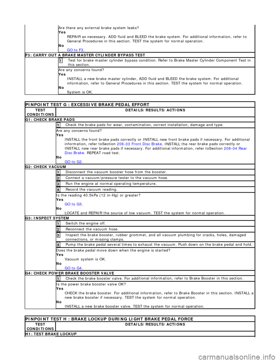
Are th
ere any external brake system leaks?
Yes REPAIR as necessary. ADD fluid and BLEED the brak e system. For additional information, refer to
General Procedures in this section. TEST the system for normal operation.
No GO to F3
.
F
3: CARRY OUT A BRAKE MASTER CYLINDER BYPASS TEST
Te
st for brake master cylinder bypass condition. Re
fer to Brake Master Cylinder Component Test in
this section.
1
A
re any concerns found?
Yes INSTALL a new brake master cylinder, ADD flui d and BLEED the brake system. For additional
information, refer to General Proc edures in this section. TEST the system for normal operation.
No System is OK.
PINPO
INT TEST G : EXCESSIVE BRAKE PEDAL EFFORT
TE
ST
CONDITIONS
D
ETAILS/RESULTS/ACTIONS
G1
: CHECK BRAKE PADS
Check the brake pads for wear, contamin
atio
n, correct installation, damage and type.
1
A
re any concerns found?
Yes INSTALL the front brake pads correctly or INSTALL ne w front brake pads if necessary. For additional
information, refer toSection 206
-03
Front Disc Brake
. INSTALL the
rear brake pads correctly or
INSTALL new rear brake pads if necessary. For additional information, refer toSection 206
-04
Rear
Di
sc Brake
. REPEAT road test.
No
GO to G2
.
G2:
CHECK VACUUM
Di
sconnect the vacuum booster hose from the booster.
1
Conne
ct a vacuum/pressure tester to the vacuum hose.
2
Ru
n the engine at normal operating temperature.
3
Re
cord the vacuum reading.
4
Is
the reading 40.5kPa (1
2 in-Hg) or greater?
Yes GO to G3
.
No
LOCATE and REPAIR the source of low vacuum . TEST the system for normal operation.
G3
: INSPECT SYSTEM
Swi
tch the engine off.
1
Re
connect the vacuum hose.
2
Inspect th
e brake booster, rubber grommet, and al
l vacuum plumbing for cracks, holes, damaged
connections, or missing clamps.
3
Pump th
e brake pedal several time
s to exhaust the vacuum. Push down on the brake pedal and hold.
4
Does th
e brake pedal move down
when the engine is started?
Yes Vacuum system is OK.
No GO to G4
.
G4
: CHECK POWER BRAKE BOOSTER VALVE
Check the brake booster valve. For
add
itional information, refer to
Brake Booster in this section.
1
Is th
e power brake booster valve OK?
Yes CHECK the brake booster. Fo r additional information, refer to Brak e Booster in this section. INSTALL a
new brake booster if necessary. TEST the system for normal operation.
No INSTALL a new brake booster valve. TEST the system for normal operation.
P
INPOINT TEST H : BRAKE LOCKUP
DURING LIGHT BRAKE PEDAL FORCE
TE
ST
CONDITIONS
D
ETAILS/RESULTS/ACTIONS
H1
: TEST BRAKE LOCKUP
Page 317 of 2490
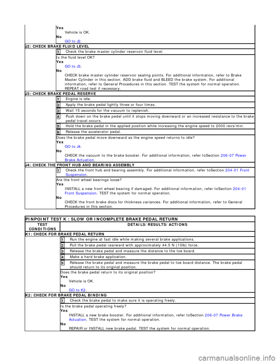
Yes
Vehicle is OK.
No GO to J2
.
J
2: CHECK BRAKE FLUID LEVEL
Check the brake master cyli
nder reservoir fluid level.
1
Is the fl
uid level OK?
Yes GO to J3
.
No
CHECK brake master cylinder reservoir sealing points. For additional information, refer to Brake
Master Cylinder in this section. ADD brake fl uid and BLEED the brake system. For additional
information, refer to General Proc edures in this section. TEST the system for normal operation.
REPEAT road test if necessary.
J
3: CHECK BRAKE PEDAL RESERVE
Engine is
idle.
1
Apply the brake pedal ligh
tl
y three or four times.
2
W
ait 15 seconds for the vacuum to replenish.
3
Push down on
the brake pedal until it stops moving
downward or an increased resistance to the brake
pedal travel occurs.
4
Hol
d the brake pedal in the applied position while increasing the engine speed to 2000 revs/min.
5
Re
lease the accelerator pedal.
6
Does th
e brake pedal move downward as
the engine speed returns to idle?
Yes GO to J4
.
No
CHECK the vacuum to the brake booster. Fo r additional information, refer toSection 206
-0
7 Power
Brake Ac
tuation
.
J
4: CHECK THE FRONT HUB AND BEARING ASSEMBLY
Check the fr
ont hub and bearing assembly. Fo
r additional information, refer toSection 204
-01
Front
Suspe
nsion
. 1
Are th
e front wheel bearings loose?
Yes INSTALL a new front wheel bearin g if damaged. For additional information, refer toSection 204
-01
F
ront Suspension
. TEST
the system for normal operation.
No CHECK the front brake discs for thickness variances. For additional information, refer to General
Procedures in this section.
PINPO
INT TEST K : SLOW OR INCOMPLETE BRAKE PEDAL RETURN
TE
ST
CONDITIONS
D
ETAILS/RESULTS/ACTIONS
K1: C
HECK FOR BRAKE PEDAL RETURN
Ru
n the engine at fast idle while
making several brake applications.
1
Pull the
brake pedal rearward with approximately 44.5 N (10lb) force.
2
Relea
se the brake pedal and measure
the distance to the toe board.
3
Make a hard brake
application.
4
Relea
se the brake pedal and measure the brake
pedal to toe board distance. The brake pedal
should return to its original position.
5
Does th
e brake pedal return
to its original position?
Yes Vehicle is OK.
No GO to K2
.
K
2: CHECK FOR BRAKE PEDAL BINDING
Check the brake pedal to make
s
ure it is operating freely.
1
Is th
e brake pedal operating freely?
Yes INSTALL a new brake booster. For addi tional information, refer toSection 206
-0
7 Power Brake
Actuation. TEST
the system for normal operation.
No REPAIR or INSTALL new brake pedal. TE ST the system for normal operation.