bumper JAGUAR X308 1998 2.G Workshop Manual
[x] Cancel search | Manufacturer: JAGUAR, Model Year: 1998, Model line: X308, Model: JAGUAR X308 1998 2.GPages: 2490, PDF Size: 69.81 MB
Page 33 of 2490

501‐17: Roof Open
ing
Panel
Description and Operation
Roof Opening Panel
General Procedures
Motor Synchronization (76.82.48)
Roof Opening Panel Alignment
Removal and Installation
Roof Opening Panel (76.82.05)
Roof Opening Panel Frame (76.82.01)
Roof Opening Panel Module (86.76.07)
Roof Opening Panel Motor (86.76.01)
Roof Opening Panel Shie
ld (76.82.06)
Roof Opening Panel Trim
Roof Opening Panel Weatherstrip (76.82.15)
501‐19: Bumpers
Specification
Description and Operation
Bumpers
Removal and Installation
Front Bumper (76.22.08)
Front Bumper and Bumper Cover (76.22.08)
Front Bumper Cover (76.22.78)
Front Bumper Isolator (76.22.31)
Rear Bumper (76.22.27) (76.22.52)
Rear Bumper Co
ver (76.22.74) (76.22.77)
Rear Bumper Isolator (76.22.70)
501‐20A : Safety Belt System
Specification
Description and Operation
Safety Belt System
Removal and Installation
Front Safety Belt Retractor (76.73.10)
Rear Safety Belt Retractor (76.73.18)
Safety Belt Shoulder Height Adjuster (76.73.12)
Page 55 of 2490
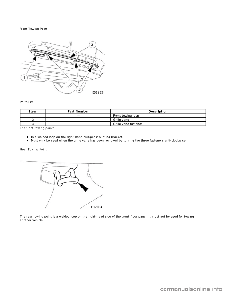
P
arts List
The front towing point:
Is a welded loop on the ri
ght-ha
nd bumper mounting bracket.
Mus
t only be used when the grille
vane has been removed by turning the three fasteners anti-clockwise.
Rear Towing Point
The rear towing point is a welded loop on the right-hand side of the trunk floor panel; it must not be used for towing
another vehicle.
It
em
Par
t Number
De
scription
1—Fr
ont towing loop
2—Gr
ille vane
3—Gr
ille vane fastener
F
ront Towing Point
Page 117 of 2490
Front Suspension - Fro
nt Stabilizer Bar
Re
moval and Installation
Materials
S
pecification
Cas
trol NTR
Remov
al
Na
me
R
ubber Suspension Insulator Lube
1. Raise front of vehicle and support on stands. Refer to Section
100-02.
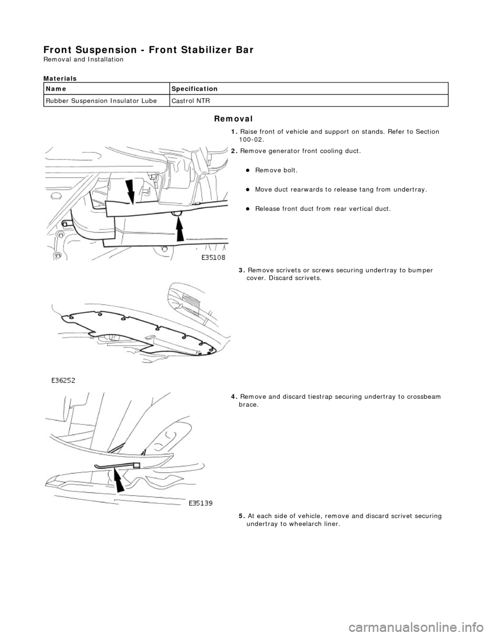
2. R
emove generator front cooling duct.
Re
move bolt.
Move duct rea
rwards to rele
ase tang from undertray.
R
elease front duct from rear vertical duct.
3. R
emove scrivets or screws se
curing undertray to bumper
cover. Discard scrivets.
4. R
emove and discard tiestrap securing undertray to crossbeam
brace.
5. At each side of vehicle, remo ve and discard scrivet securing
undertray to wheelarch liner.
Page 120 of 2490

Install but do not tighten
stabilizer bar LH mounting
bracket securing bolts.
Inst al
l stabilizer bar RH moun
ting bracket securing bolts
and tighten to 30-40Nm.
Tigh ten LH mountin
g bracke
t bolts to 30-40Nm.
6. Secure link arms to
stabilizer bar.
Tighten LH li
nk arm ball joint to stabilizer bar securing nut
to 60-80Nm.
Ti ghten R
H link arm ball joint to stabilizer bar securing nut
to 60-80Nm.
7. Using screws or new scrivets , secure undertray to fr
ont
bumper cover.
8. Usi n
g a new tiestrap, secure undertray to crossbeam brace.
9. Using new scrivets, secure un dertray to each wheelarch
liner.
Page 122 of 2490
Front Suspension - Front Stabilizer B
ar Bushing
Re
mo
val and Installation
Materials
S p
ecification
Cas
t
rol NTR
Remov
a
l
Na
m
e
R
u
bber Suspension Insulator Lube
1. Raise front of vehicle and support on stands. Refer to Section
100-02.
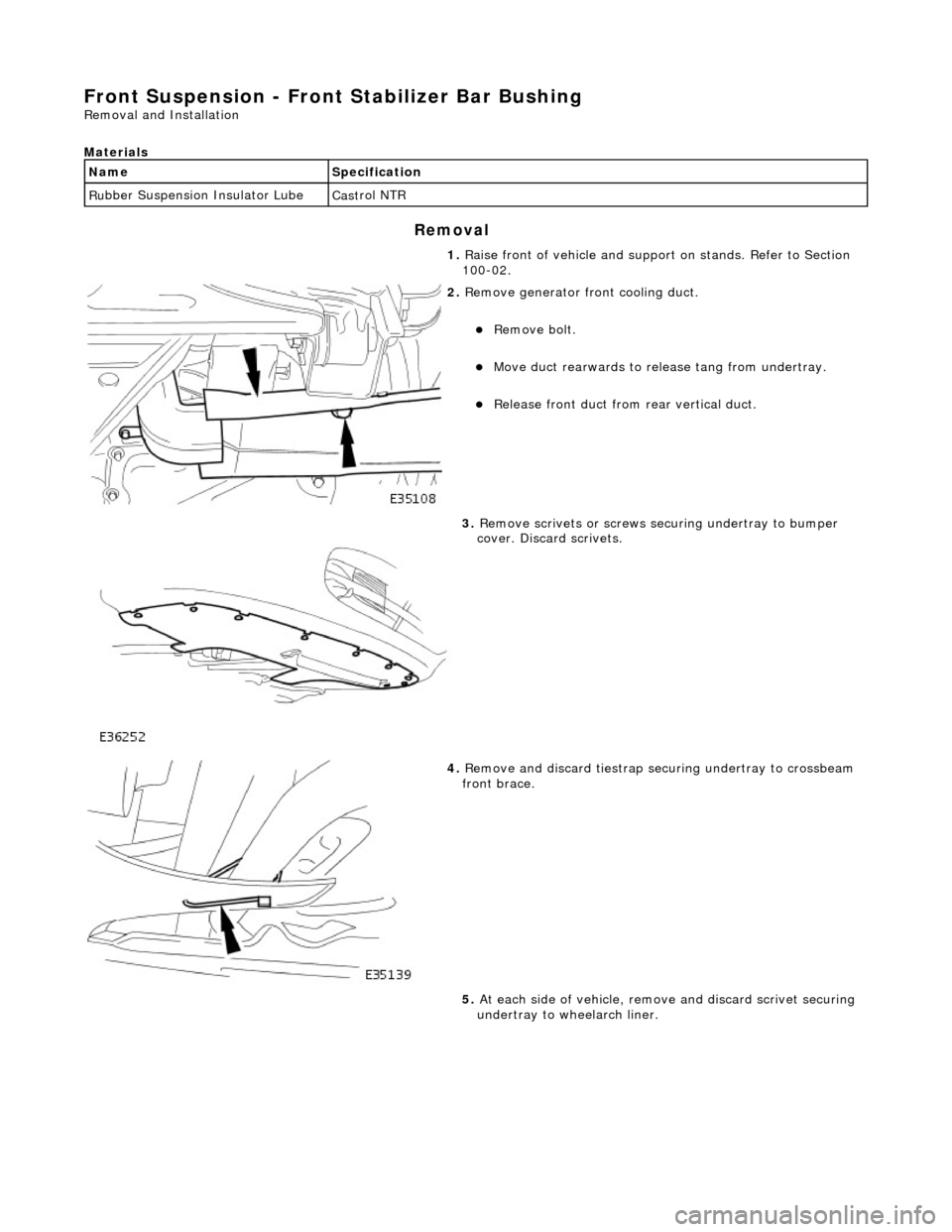
2. Re
move generator front cooling duct.
Re
mo
ve bolt.
Move duct rea
r
wards to rele
ase tang from undertray.
Re
lease front duct from rear vertical duct.
3. Re
move scrivets or screws se
curing undertray to bumper
cover. Discard scrivets.
4. Re
move and discard tiestrap securing undertray to crossbeam
front brace.
5. At each side of vehicle, remo ve and discard scrivet securing
undertray to wheelarch liner.
Page 125 of 2490
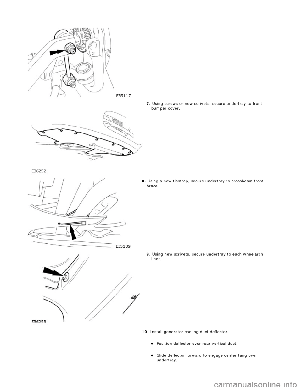
7. Using screws or new scrivets , secure undertray
to front
bumper cover.
8. Usi
ng a new tiestrap, secure undertray to crossbeam front
brace.
9. Usi
ng new scrivets, secure un
dertray to each wheelarch
liner.
10. Install generator cool ing duct deflector.
Po
sition deflector over
rear vertical duct.
Sl
ide deflector forward to
engage center tang over
undertray.
Page 931 of 2490
s
ystem (pressure).
Outputs from the ECM control the radiator fans control module, located behind the left hand side of the bumper, to operate
the fans in the series mode (slow), paralle l mode (Fast) or Off modes. Hysteresis in the temperature and pressure switching
values prevents 'hun ting' between modes.
Under hot operating conditions, the fans may continue to operat e for some time after the engine has been switched off, but
will stop automatically when the coolant te mperature has been sufficiently reduced.
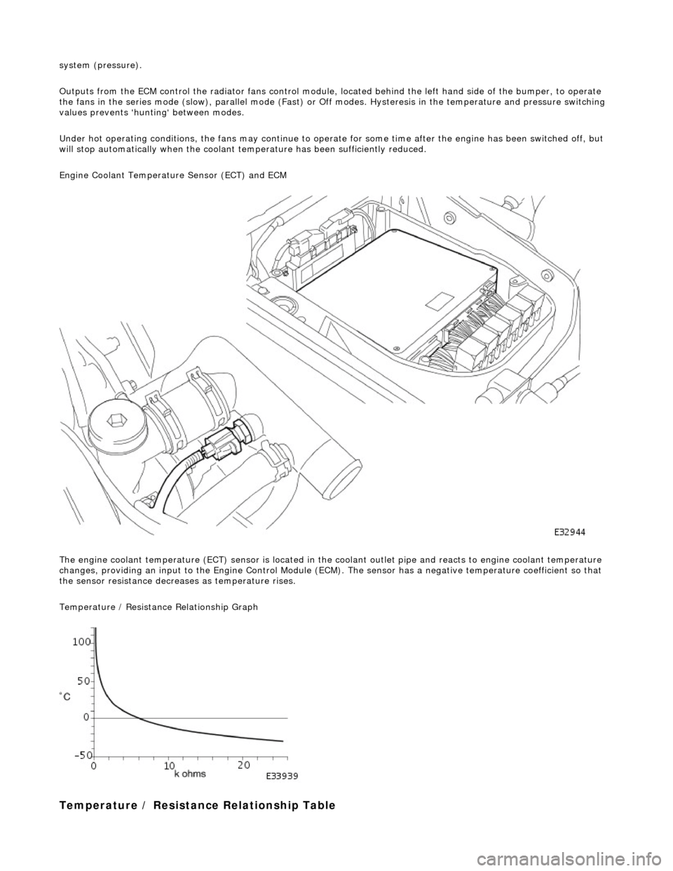
Engine Coolant Temperature Sensor (ECT) and ECM
The engine coolant temperature (ECT) sensor is located in the coolant outlet pipe and reacts to engine coolant temperature
changes, providing an input to the Engine Control Module (ECM). The sensor has a negative te mperature coefficient so that
the sensor resistance decrea ses as temperature rises.
Temperature / Resistance Relationship Graph
T
emperature / Resistance
Relationship Table
Page 1126 of 2490
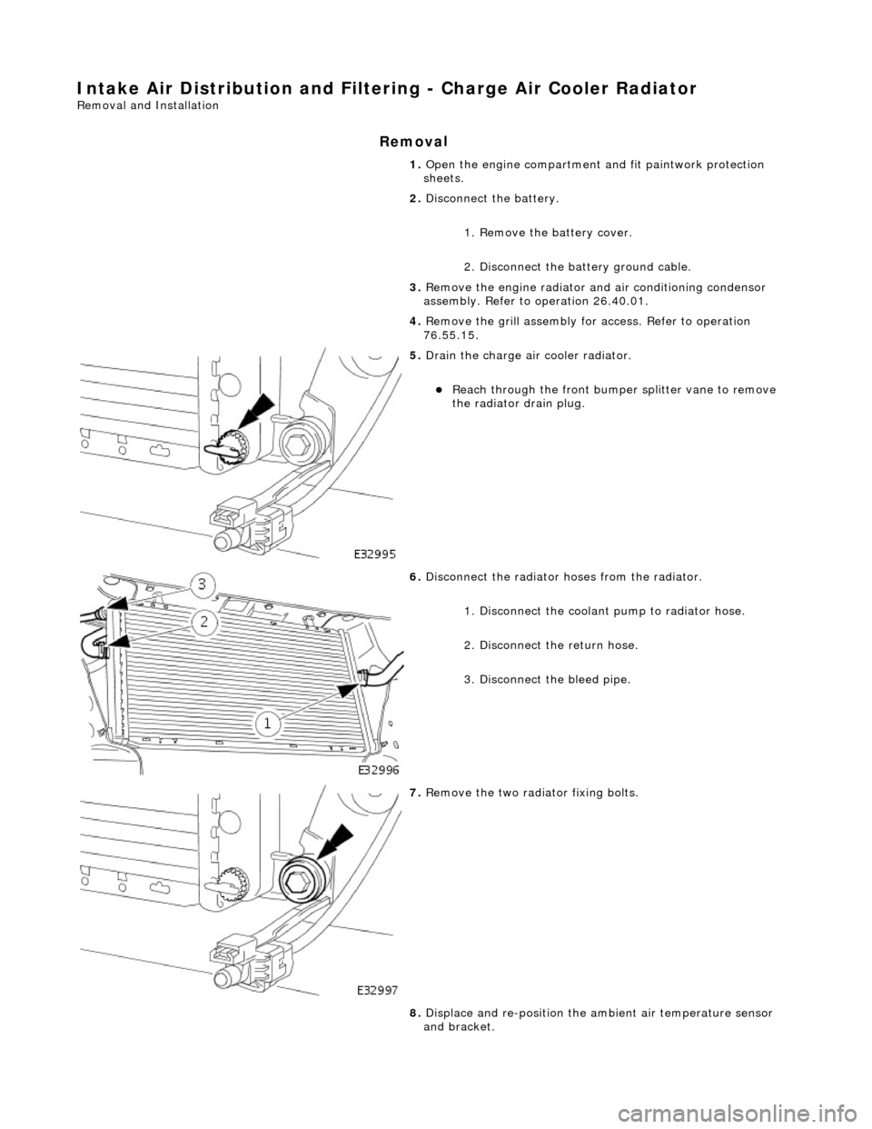
Intake Air Distribution and Filtering - Charge Air Cooler Radiator
Remo
val and Installation
Remov
a
l
1.
Op
en the engine compartment and fit paintwork protection
sheets.
2. Disconnect the battery.
1. Remove the battery cover.
2. Disconnect the battery ground cable.
3. Remove the engine radiator and air conditioning condensor
assembly. Refer to operation 26.40.01.
4. Remove the grill assembly fo r access. Refer to operation
76.55.15.
5. Drain th e charge air cooler radiator.
Reach t
hrough the front bumper
splitter vane to remove
the radiator drain plug.
6. Disc
onnect the radiator
hoses from the radiator.
1. Disconnect the coolant pump to radiator hose.
2. Disconnect the return hose.
3. Disconnect the bleed pipe.
7. Re
move the two radiator fixing bolts.
8. Displace and re-position the am bient air temperature sensor
and bracket.
Page 1527 of 2490

Rear Muffler Assembly
The left-hand and right-hand rear muffler assemblies comprise:
Absorption type muffler. Inlet pipe and tailpipe welded to the muffler. Tailpipe bright finisher integral with the tailpipe.
Tailpipe Clearance to Moulded Bumper
Page 1841 of 2490

Control Components - Ambient Air Temperature Sensor
Removal and Installation
Removal
Installation
1. NOTE: The ambient temperature sensor is accessed through
the bumper vane.
Detach sensor from bracket and disconnect connector.
1. Installation is a reversal of the removal procedure.